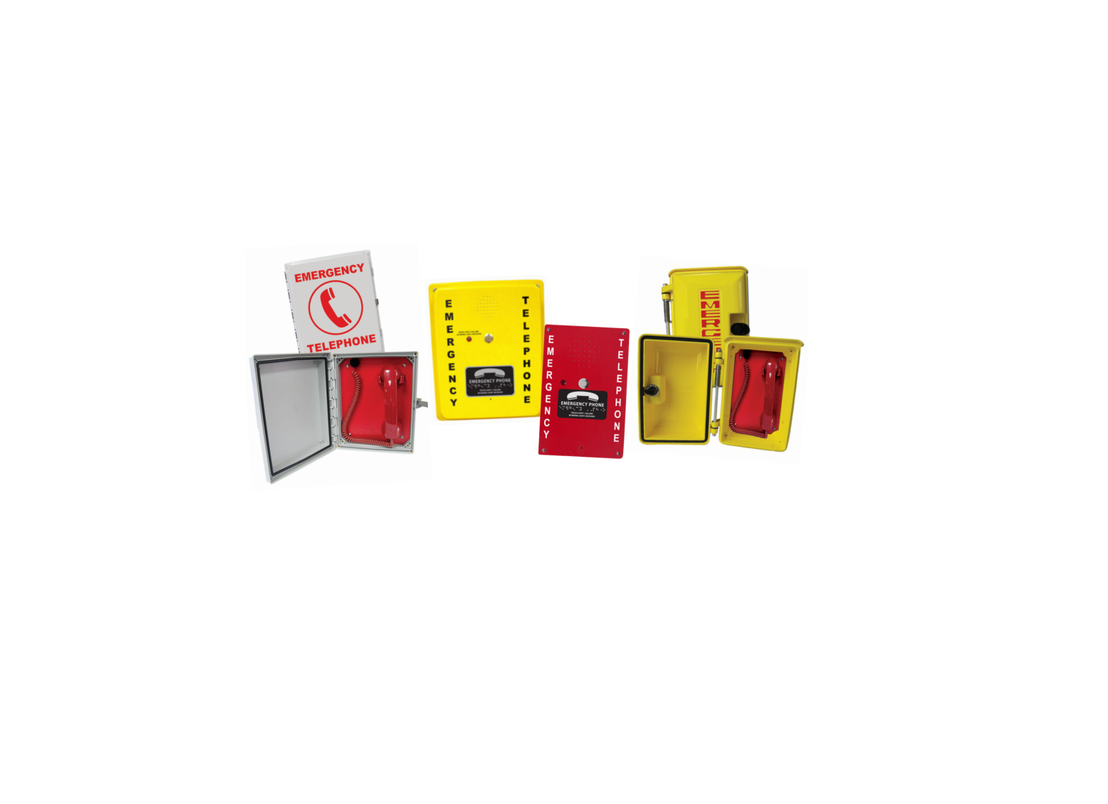
RATH 984POOL Analog Pool Phones
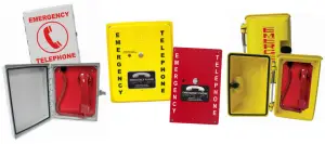
Thank you for purchasing a RATH® Analog Pool Phone. We are the largest Emergency Communication Manufacturer in North America and have been in business for over 35 years.
We take great pride in our products, service, and support. Our Emergency Products are of the highest quality. Our experienced customer support teams are available to remotely assist with site preparation, installation, and maintenance. It is our sincere hope that your experience with us has and will continue to surpass your expectations.
Thank you for your business,The RATH® Team
Mounting
624POOL, 624MPOOL, 970POOL

Items Needed:
- Live analog phone line
- Drill · Drill bit or knockout set
- Biscuit jack (provided with 624POOL & 624MPOOL)
- Mounting screws
- Conduit with water tight connector
- 1/8″ Allen wrench (provided)
- Screwdriver
- Mounting feet (provided)
Installation:
- After opening door on unit, use the Allen wrench to remove the 4 screws securing the internal plate.
- Completely remove the internal plate.
- Using a drill bit or knockout set, drill a hole in the bottom of the enclosure large enough for the water tight connector.Note: Be sure the hole sits far enough back so it doesn’t interfere with the internal plate when it’s reinstalled.
- Turn enclosure over and screw 1 mounting foot onto each mounting hole on the back of the enclosure using provided screws.
- Using appropriate mounting screws, screw enclosure to the wall using the other side of the mounting feet.
- Run telephone line in conduit, bring line into the enclosure through the water tight connector, and tighten conduit to connector.
- Connect incoming line to the biscuit jack, then plug the line cord connected to circuit board to the RJ11 jack on the biscuit jack.Note: Do not cut RJ11 jack of supplied line cord and splice phone line onto it.
- Phone is preset to dial 911. If required to call an alternate number not given to RATH® at time of purchase, please follow programming instructions on page 6. If phone is calling 911, screw internal plate back into place. Unit is ready for testing. The 624MPOOL is a manual dial phone and will not have a preset number.Note: If phone does not have a dial tone when handset is lifted, please reverse polarity of incoming phone line.
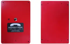
984POOL, 984POOLC1
Items Needed:
- Live analog phone line
- Drill
- Drill bit or knockout set
- Biscuit jack
- Mounting screws
- #10 spanner bit (provided)
- Conduit with water tight connector
- Screwdriver
Installation:
- Using the spanner bit, remove the 4 screws holding the front cover in place and remove the cover.
- Using a drill bit or knockout set, drill a hole in the bottom of the enclosure large enough for the water tight connector.
- Using appropriate mounting screws, screw enclosure onto the wall.
- Run telephone line in conduit, bring line into the enclosure through the water tight connector, and tighten conduit to connector.
- Connect incoming line to RJ11 connector and plug into RJ11 jack on board. Or, obtain a biscuit jack, terminate your incoming line to the biscuit jack and plug the included phone line to the RJ11 connector on the biscuit jack.Note: Do not cut RJ11 jack of supplied line cord and splice phone line onto it.
- Phone is preset to dial 911. If required to call an alternate number not given to RATH® at time of purchase, please follow programming instructions on page 6. If phone is calling 911, screw internal plate back into place. Unit is ready for testing.
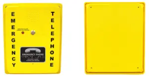
690RDPOOL, 990RDPOOL, 690SYPOOL (YELLOW), 990SYPOOL (YELLOW)

Items Needed:
- Live analog phone line
- Drill
- Metal capable drill bit or knockout set
- Biscuit jack (provided with 690SYPOOL & 690RDPOOL)
- Mounting screws
- Wall anchors
- Conduit with water tight connector
- 3/32″ Allen wrench (provided)
- Screwdriver
Installation:
- After opening door on unit, use the Allen wrench to remove the 4 screws securing the internal plate.
- Completely remove the internal plate.
- Using a drill bit or knockout set, drill a hole in the bottom of the enclosure large enough for the for the water tight connector.Note: Be sure the hole sits far enough back so it doesn’t interfere with the internal plate when it’s reinstalled.
- Using appropriate mounting screws and anchors, screw enclosure to the wall.
- Run telephone line in conduit, bring line into the enclosure through the water tight connector, and tighten conduit to connector.
- 690SYPOOL & 690RDPOOL: Connect incoming line to the biscuit jack, then plug the line cord connected to circuit board to the RJ11 jack on the biscuit jack.
- 990SYPOOL & 990RDPOOL: Connect incoming line to RJ11 connector and plug into RJ11 jack on board. Or, obtain a biscuit jack, terminate your incoming line to the biscuit jack, and plug the included phone line to the RJ11 connector on the biscuit jack.Note: Do not cut RJ11 jack of supplied line cord and splice phone line onto it.
- Phone is preset to dial 911. If required to call an alternate number not given to RATH® at time of purchase, please follow programming instructions on page
- If phone is calling 911, screw internal plate back into place. Unit is ready for testing.
2400-886DA
Items Needed:
- Live analog phone line
- Drill
- Drill bit or knockout set
- Biscuit jack
- Mounting screws
- #10 spanner bit (provided)
- Conduit with water tight connector
- Screwdriver
- Mounting feet (provided)
Installation:
- Using the spanner bit, remove the 4 screws holding the front cover in place and remove the cover.
- Using a drill bit or knockout set, drill a hole in the bottom of the enclosure large enough for the water tight connector.
- Turn over the back of the enclosure and screw 1 mounting foot onto each mounting hole using the supplied screws.
- Run telephone line in conduit, bring line into the enclosure through the water tight connector, and tighten conduit to connector.
- Connect incoming line to RJ11 connector and plug into RJ11 jack on board. Or, obtain a biscuit jack, terminate the incoming line to the biscuit jack and plug the included phone line to the RJ11 connector on the biscuit jack.Note: Do not cut RJ11 jack of supplied line cord and splice phone line onto it.
- Phone is preset to dial 911. If required to call an alternate number not given to RATH® at time of purchase, please follow programming instructions on page 6. If phone is calling 911, screw internal plate back into place. Unit is ready for testing.
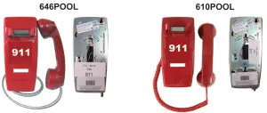
646POOL, 610POOL
Items Needed:
- Live analog phone line
- Female RJ11 wall plate
- Screwdriver
Installation:
- On the back of the unit, plug the line cord into female RJ11 wall plate.
- Phone should slide onto wall plate and clip itself into place.
- Phone is preset to dial 911. If required to call an alternate number not given to RATH® at time of purchase, please follow programming instructions on page 6. If phone is calling 911, screw internal plate back into place. Unit is ready for testing.Note: To open unit up for programming, use a small flat head screwdriver to gently lift the plastic covering window on the front of the unit. Lift the logo after plastic is removed. Use a screwdriver to remove the 2 screws. Once screws are loosened, gently lift up and out the red plastic housing on the underside of the phone. The red housing should come off completely exposing the keypad.
Programming
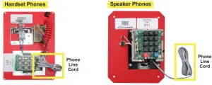
Handset Phones
Most Pool Phones are already pre-programmed to call 911. Only perform the following if you want the phone to call somewhere other than 911. Please choose one of the options below that matches the type of line that the phone is installed on:
- Standard Telephone Line ProgrammingNote: When programming, ignore messages or busy tones in the background.a. Start with phone handset hung upb. Press and hold Program button, lift handset off hook, then release Program buttonc. Press the # key 10 times (you will hear confirmation tones in the handset)d. Press 3, #, then the phone number you want the phone to diale. Press *, # to exit Programming Mode, then hang up the handset
- Switchboard Telephone Line Programming (Hotel Industry)Note: When programming, ignore messages or busy tones in the background. a. Start with phone handset hung up b. Press and hold Program button, lift handset off hook, then release Program button c. Press the # key 10 times (you will hear confirmation tones in the handset) d. Press 3, #, then press the access code for an outside line (usually 8 or 9) e. Press #, *, then the phone number you want the phone to dial f. Press *, # to exit Programming Mode, then hang up the handset
- Ring-Down Telephone Line Programminga. Start with phone handset hung upb. Press and hold Program button, lift handset off hook, then release Program buttonc. Press the # key 10 times (you will hear confirmation tones in the handset)d. Press 3 then #e. Press # then *f. Press *, # to exit Programming Mode, then hang up the handset
Speaker Phones
Most Pool Phones are already pre-programmed to call 911. Only perform the following if you want the phone to call somewhere other than 911. Please choose one of the options below that matches the type of line that the phone is installed on:
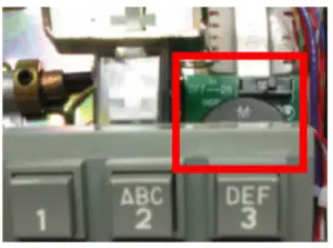
- Standard Telephone Line Programminga. Press red ON/OFF button, phone should get dial tone, then slide S15 to ON/PROGb. Press 1, *, (key in phone number you want the phone to dial), then press blue VOL buttonNote: If a pause is needed as a part of the dialing, press the red ON/OFF button.c. Slide S15 back to 1 position, then press red ON/OFF button
- Switchboard Telephone Line Programming (Hotel Industry)a. Press red ON/OFF button, phone should get dial tone, then slide S15 to ON/PROG b. Press 1, *, key in access code (usually 8 or 9), press ON/OFF, (key in phone number you want the phone to dial), then press blue VOL key c. Side S15 back to 1 position, then press red ON/OFF button
- Ring-Down Telephone Line Programminga. Press red ON/OFF button, wait for operator to answer call, then slide S15 to ON/PROGb. Press 5, *, 2c. Slide S15 back to 1 position, then press red ON/OFF button
Wiring
Adjusting the Volume
Handset Phones
On the underside of the handset, turn volume wheel to increase or decrease volume.
Speaker Phones
On the internal keypad, press the red ON/OFF button. While phone is sitting with dial tone, press the blue VOL key. Each time the VOL key is pressed, the phone will cycle through 3 volume levels. When desired volume level is reached, press the red ON/OFF button again.
Turning Ringer On/Off
624MPOOL
- Open door on unit and remove 4 screws securing the red internal plate. Lift the plate out and flip it over to expose the keypad.
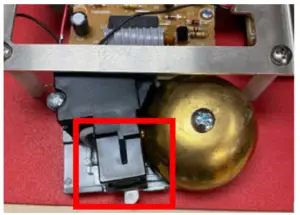
- Under the keypad, locate the brass ringer bell.
- Next to the bell is a plastic slide hammer. Slide the hammer to the left about halfway to enable the ringer. To disable the ringer, slide the hammer all the way to the right
- Screw internal plate back into place and shut the door on the unit.

624POOL, 690SYPOOL, 690RDPOOL
- Open door on unit and remove 4 screws securing the red internal plate. Lift the plate out and flip it over to expose the keypad.
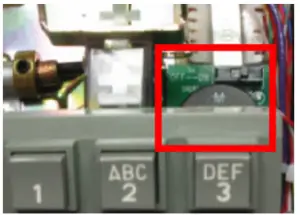
- Above and slightly underneath the keypad will be a small dipswitch labeled “ON” and “OFF”. Slide dipswitch to “ON” to enable the ringer or “OFF” to disable the ringer.
- Screw internal plate back into place and shut the door on the unit.
610POOL, 646POOL
- Open unit up by using a small flat head screwdriver to gently lift the plastic covering on the small white rectangular box on the cover of the unit.
- Remove the white paper to expose the two cover screws and loosen them with a small Philips screwdriver.
- Gently lift up and out the red plastic housing on the underside of the phone.
- Once keypad is exposed, underneath the keypad is a small dipswitch labeled “ON” and “OFF”. Slide dipswitch to “ON” to enable the ringer or “OFF” to disable the ringer.
- Put the housing back on the unit and screw into place. Cover screws with paper and plastic removed in step 1.
984POOL, 984POOLC1, 2400-886DA
- Remove 4 security screws in each corner of the unit using supplied spanner bit.
- Flip cover over to expose internal keypad.
- Use a Philips screwdriver to remove the 4 screws holding the circuit board to the enclosure. Note: Under the circuit board there are 4 plastic washers that go inbetween the circuit board and the enclosure. Do not lose these washers. Set aside in a safe location unit you are ready to reassemble.
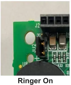
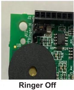
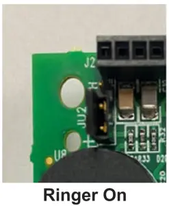
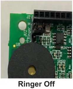
- Flip circuit board over and above the round black piezo in the top left-hand corner is the ringer jumper.
- To enable the ringer, set the jumper onto the two pins closest to the black piezo. To disable the ringer, set the jumper sideways onto the center pin. See pictures for exact positioning.
- Screw circuit board back onto enclosure making sure washers are in between the board and the metal standoffs.
- Screw cover back onto unit.
970POOL, 990RDPOOL, 990SYPOOL
- Open door on unit and remove 4 screws securing the red internal plate. Lift the plate out and flip it over to expose the keypad.
- Use a Philips screwdriver to remove the 4 screws holding the circuit board to the plate.Note: Under the circuit board there are 4 plastic washers that go in between the circuit board and the plate. Do not lose the washers. Set aside in a safe location unit you are ready to reassemble.
- Flip circuit board over and above the round black piezo in the top left-hand corner is the ringer jumper.
- To enable the ringer, set the jumper onto the two pins closest to the black piezo. To disable the ringer, set the jumper sideways onto the center pin. See pictures for exact positioning.
- Screw circuit board back onto plate making sure washers are in between the board and the metal standoffs.
- Screw internal plate back into place and shut the door on the unit.
 report this ad
References
[xyz-ips snippet=”download-snippet”]