Installation & Operations Manual
Command Center
Made in the USA 3 Year Warranty
N56W24720 N. Corporate Circle Sussex, WI 53089 800-451-1460 www.rathcommunications.comRP8500PBXG Ver. 6 12/20
Thank you for purchasing a RATH® Command Center. We are the largest Emergency Communication Manufacturer in North America and have been in business for over 35 years.We take great pride in our products, service, and support. Our Emergency Products are of the highest quality. Our experienced customer support teams are available to remotely assist with site preparation, installation, and maintenance. It is our sincere hope that your experience with us has and will continue to surpass your expectations.Thank you for your business,The RATH® Team
Items Needed
Included:
- Command Center Phone (will be mounted in a cabinet or include a desk mount stand for desk mount)
- Distribution Module
- System wiring (pigtail cables, power cord, phone line cord, Ethernet cable)
- 1/8″ Hex Allen Wrench (cabinet mount models only)
Not Included:
- Minimum 22 or 24 AWG twisted, shielded cable
- 120vac power
- Multimeter
- Analog phone (recommended for troubleshooting)
- Analog or digital phone line (only if the system needs the ability to call out)
- Small Phillips screwdriver
- Mounting hardware
- Power supply with battery backup (RATH® part #RP7700104 or RP7701500)
- RATH® 2100 or 2400 series phones
Typical System Layout

Installation Steps
- Mount the Distribution Module and power supply with battery backup in an appropriate location (a network closet or machine room is recommended).
- Plug the power supply with battery backup into a standard 120v wall outlet. Note: System is to be powered by a grounded 120v, 60Hz, AC outlet protected by a 15A maximum circuit breaker. Note: If using the RP7701500, ensure the unit has charged for a minimum of 8 hours before system testing. For more information, refer to the RP7701500 User Manual included with the unit.
- Using the provided power cord, plug the 3-pin female connector side into power input next to the power switch on the Distribution Module. Plug the male 3-prong side of the power cable into any of the open outlets on the back of the power supply with battery backup. Wait to power on the Distribution Module until all connections are made.
- Install the Command Center Phone:Desk Mount: Install the foot stand on the back of the Command Center phone and choose location per owner’s specifications. If the system is over 16 zones, connect additional button consoles to the Command Center using the provided extenders. Refer to the diagram below for attaching the extenders and foot stands.
 Cabinet Mount: Use the provided Allen Wrench to remove the back box or back plate from the cabinet. Remove any applicable knockouts. Mount the backbox or plate in location per owner’s specifications using appropriate mounting hardware. Reassemble the cabinet.
 - Run a single 22 or 24 AWG twisted, shielded cable from the Command Center phone back to the Distribution Module. This single cable provides communication and power. No additional power is needed. Note: The maximum wire run length from the Distribution Module to the Command Center is 6,200′ feet for 22 AWG and 3,900′ feet for 24 AWG.
- Using a biscuit jack, screw the twisted, shielded pair landed at the Command Center side to the red and green screws of the biscuit jack. Plug the phone line cord provided with the Command Center into the female RJ11 jack on the biscuit jack. Plug the other end of the phone line cord into the input port on the back of the Command Center.
- Run at minimum a single 22 or 24 AWG twisted, shielded pair from each phone back to the Distribution Module.Note: The maximum wire run length from the Distribution Module to a phone is 112,500′ feet for 18 or 22 AWG and 70,300′ feet for 24 AWG.IF A USING RATH® SUPERVISOR BOARD, MAXIMUM WIRE RUN LENGTH CANNOT EXCEED 4,000′ FT.
- Make connections to phones:Area of Refuge Applications: Use a biscuit jack to screw the twisted, shielded pair landed at the phone side to the red and green screws on the biscuit jack. Plug the phone line cord provided with the phone into the female RJ11 jack on the biscuit jack. Plug the other end of the phone line cord into the RJ11 jack on the back of the circuit board in the phone.Elevator Applications: Take a twisted, shielded pair and wire the pair the same way the elevator manufacturer calls for, as if a standard analog phone line was being used.
Distribution Module Wiring
Option 1: 12-36 Zone SystemsFor 12-36 zone systems, remove the screws on the back of the Distribution Module and remove the cover to expose the internal RJ45 connections.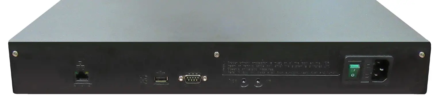
- Each card installed will have three RJ45 connections
- On top of each RJ45 port, there is a label indicating connection:
- SLT is the port used for connecting Emergency Phones
- DKP is the port used for connecting Command Center Phone
- TWT is the port used for outside Telco Line
- Plug the supplied RJ45 pigtail cables into the RJ45 connections on the Distribution Module following the wiring chart and pin-out color scheme below
- Refer to the top of the cards to see what type of RJ45 port and number of extensions
- The same pin-out color scheme should be used for the primary card and for all additional cards
- The system uses T568-A for pin-out wiring
- The first card installed will always be:
- Port 1: (01-04) Connection for 4 Emergency Phones (SLT)
- Port 2: (05-06) Connection for 2 Telco Lines (TWT)
- Port 3: (07-08) Connection for up to 2 Command Center Phones (DKP)
- All cards after Card 1 will always be used for connecting additional Emergency Phones. For Card 2:
- Port 1: (01-04) Connection for 4 Emergency Phones
- Port 2: (05-06) Connection for 2 Emergency Phones
- Port 3: (07-08) Connection for 2 Emergency Phones
Note: DO NOT plug anything into the sixth card labeled “VMS”.
- Once all RJ45 connections are made, connect twisted, shielded pairs onto pigtail sides of the wiring harnessesOption 2: 56-96 Zone Systems
- Each card installed will have six RJ45 connections
- On top of each RJ45 interface there is a label indicating connection:
- S01-S_ is the port used for connecting Emergency Phones
- TD (1-2)(3-4) with a dot under the D is the port used for connecting Command Center Phone(s)
- TD (1-2)(3-4) with a dot under the T is the port used for outside Telco Line
- Plug the supplied RJ45 pigtail cables into the RJ45 interface connections following the wiring chart and pin-out color scheme below
- Refer to the top of the cards to see what type of RJ45 interface and number of extensions
- The same pin-out color scheme should be used for the primary card and for all additional cards
- The system uses T568-A for pin-out wiring
- The first card installed will always be:
- Port 1: (S01-S04) Connection for 4 Emergency Phones
- Port 2: (S05-S08) Connection for 4 Emergency Phones
- Port 3: (S09-S12) Connection for 4 Emergency Phones
- Port 4: (S13-S16) Connection for 4 Emergency Phones
- Port 5: (D1-2) Connection for up to 2 Command Center Phones
- Port 6: (T1-2) Connection for up to 2 outside Telco Lines
- All cards after Card 1 will always be used for connecting additional Emergency Phones. For Card 2:
- Port 1: (01-04) Connection for 4 Emergency Phones
- Port 2: (05-08) Connection for 4 Emergency Phones
- Port 3: (09-12) Connection for 4 Emergency Phones
- Port 4: (13-16) Connection for 4 Emergency Phones
- Port 5: (17-18) Connection for 2 Emergency Phones
- Port 6: (19-20) Connection for 2 Emergency Phones
- Once all RJ45 connections are made, connect twisted, shielded pairs onto the pigtail sides of the wiring harnesses9. Turn on the 120vac supply (if not already done).10. Turn on the Distribution Module.

Sub-Master Phones
A RATH® Command Center System comes with a single base station phone. It can accommodate one additional base station phone which connects to the second DKP port on the first card. If your system includes more than two additional base station phones, there will be an additional card of just DKP ports. The additional base station wires will wire back to the Distribution Module the same way as the main Command Center described on page 4.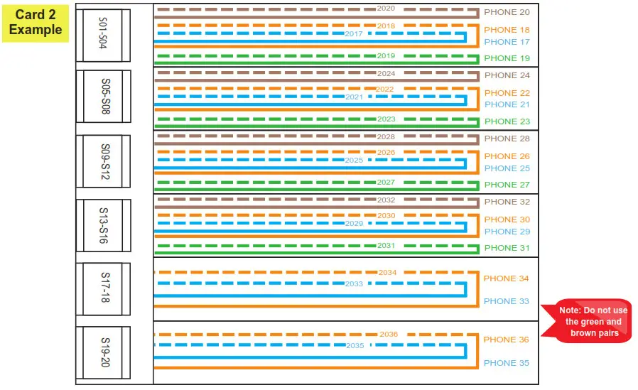
Machine Room Phones
A RATH® Command Center can have multiple “Machine Room” Phones connected to it. Machine Room Phones (RATH® part # 2300-630RC) are used to call any of the connected phones from a location other than where the primary Command Center is located. The 2300-630RCs wire the same way as the phones. After connecting all 2300-630RCs, wire a single twisted, shielded 22 or 24 AWG pair from any of the open SLT ports on the Distribution Module to a female RJ11 wall plate (not included). Connect a male RJ11 cord on the back of the 2300-630RC and plug it into the wall plate. Slide the 2300-630RC down onto the wall plate to mount in place.To place a call from the 2300-630RC to the phones, lift the handset and dial the extension number of the phone you are trying to reach (Example: Phone 1 = 2001, Phone 2 = 2002). To call from the 2300-630RC to the Command Center phone, lift the handset and dial 0.
Setting the Date and Time
Perform the following steps on the Command Center phone.
- Enter Program Mode:a. Dial 1#91b. Enter Password 7284
- Program the time zone:a. Dial 1002 followed by the appropriate time zone code:Eastern Time Zone = 111 Mountain Time Zone = 113Central Time Zone = 112 Pacific Time Zone = 114b. Touch the GREEN button in the middle of the phone when finished
- Program the date (month-day-year format):a. Dial 1001 followed by the date (Example: 1001 15 02 2011 for February 15, 2011)b. Touch the GREEN button in the middle of the phone when finished
- Program the time (military time including hour-minute-second):a. Dial 1003 followed by the time (Example: 1003 143000 for 2:30pm) b. Touch the GREEN button in the middle of the phone when finished
- To exit Program Mode dial 00 followed by the GREEN button
Emergency Phone Programming
The phones are pre-programmed for Memory Location 1 to dial 3931 in order to call the Command Center first.Note: Phones for elevator installations are not pre-programmed.
The system can be programmed to dial an outside number if the call is not answered at the Command Center (optional). To do this, perform the following steps at the Command Center:
- Press the speaker phone button
- Dial 1, 3, 4
- Dial 9, the external number, #, * to store the number
- Verify the Command Center display shows “Forwarded On” followed by the phone number entered
- Press the Speaker Phone button to hang upNote: To turn off call forwarding, dial 1, 3, followed by the green button.
- Program or modify the location message for the phone. All phones come with a default location message. Message must be changed or disabled on all phones.
Option 1: 2100 Series Phones
- Press ENTER to enter Programming Mode
- Press 1, 3, ENTER, 3
- Press 6, RECORD key, after the beep speak message adding, “For two-way communication, press * at any time” to the end, STOP
- Press 6, PLAY/PAUSE to play message back
- Press and hold STOP for 3 seconds to exit programmingNote: For no message, press ENTER to enter programming, 1, 3, ENTER, 0, press and hold STOP for 3 seconds.
Option 2: 2400 Series Phones
- Press the ON/OFF button on the keypad inside of the phone
- Slide the S15 switch down into the ON/PROGRAM position
- Press 7, *, 3
- Press 4, *, when beeping ends speak message adding, “For two-way communication, press # four times after the beep” to the end, press blue VOL key
- After the blue VOL key is pressed, message will playback
- Slide the S15 switch back up into the “1” position
- Press the ON/OFF button on the keypad inside of the phoneNote: For no message, press the ON/OFF button, slide the S15 switch into ON/PROGRAM, press 7, *, 0, slide the S15 switch back to the “1” position, and press the ON/OFF button again.
Operating Instructions
Indicator Status:
- Red LED Light: Incoming call or connected to outside party
- Blue LED Light: Active call
- Blue LED Flashing: Call on hold
Answering Call at Command Center:
- Lift the handset to answer the first incoming call. The Command Center must ring before the call can be answered.
- If multiple calls are coming in, press the red LED light next to the desired call (this will place the original call on hold).Note: The phone may be in the process of playing the location message when the call is answered at the Command Center. Follow the prompts in the location message to stop the message and establish two-way communication.
Disconnecting Calls:
- Select the desired flashing blue LED and press the *, # buttons.
- Each call must be disconnected individually.Note: If you hang up the handset before disconnecting each call, the LED(s) will remain illuminated. Lift the handset, press the illuminated LED, the number 5 button, then *, #. To disconnect, hang up the handset. Repeat for each illuminated LED.
Joining a Call Already in Progress:
- Pick up the handset, press the red LED, then the number 5 button.
- You will be in a three-way conversation with the outside party and location.
report this adCalling a Location:
- Pick up the handset and press the button for desired location.
Troubleshooting
| Problem | Possible Cause & Solutions |
| Command Center will not power on: | • Check wires for voltage. Voltage should be 28vdc.• If no voltage is detected. confirm you are connected to the DKP interface on the Distribution Module.• If you have 48vdc. you are incorrectly connected to an SLT interface. |
| Phones will not call out: | • Check wires for voltage. Voltage should be 48vdc.• If no voltage is detected, confirm you are connected to the SLT interface on the Distribution Module (some SLT interfaces only use the blue and orange pairs).• If you have 28vdc. you are incorrectly connected to the DKP interface.• Make sure you dial any access digit that may be required to dial out of the building. |
| Phones will make internal calls but not external calls: | • Check that the phone line is connected to the correct interface on the Distribution Module.• Verify the phone line by making sure it has 48-52vdc on the line and use an analog phone to verify you are able to call in and out. |
| Insufficient volume on phones: | • To adjust the volume on 2100 Series SmartPhones. turn the VR1 potentiometer.• To adjust the volume on 2400 Series Phones. use the VOL key. |
| Light continuously blinks on button for phone: | • The phone is not properly hung up. Lift the Command Center handset. select the blinking light then hang up the handset. |
| Lights periodically blink on Command Center: | • This indicates that the phone is doing a phone line check. This is a normal function of the system and no action is needed.• To disable this function, refer to the 2100 Series SmartPhone Programming Guide. |
| Message won’t stop playing: | • For a 2400 Series Phone. verify that the answering party is pressing the # key 4 times AFTER the beep.• Verify the verbiage in the message includes instructions on how to stop the message.• Message can only be stopped during the 3 second gap after the first message ends and before the second message begins. |
| Calls won’t forward out: | • Verify call forwarding has been set up on the Command Center.• Verify the Command Center can place a call out by lifting the handset, dialing 9. then a phone number. If a message shows up on the Command Center screen saying. ‘All Trunks Busy-. the system does not have an active phone line connected to it.• Verify dialing string for forwarding number. |
| Blue light in the top right corner of the Command Center won’t stop blinking: | • A blinking light indicates a missed call.• To dear missed calls. dick the button under ‘LOGS’ on the Command Center screen. When the screen displays ‘Missed Calls” click the green button on the Command Center and use the arrows to scroll up and down to view the calls. Press the speaker phone button to exit. |
References
[xyz-ips snippet=”download-snippet”]