

Safety Information
DA NGER! Avoid Pow erlines! When following the instructions in this guide to install and connect the satellite antenna and connections, take extreme care to avoid contact with overhead power lines, lights and power circuits. Contact with power lines, lights, and power circuits may be fatal.
CAUTIONBefore connecting the DSS® receiver, read the Safety Information that came packed with the DSS® receiver.
Outdoor Dish A ntenna GroundingThe outdoor dish antenna used to receive satellite signals and the cable used to connect the outdoor dish antenna to the indoor receiving unit are required to comply with local installation codes and the appropriate sections of the National Electrical Code (NEC), especially Articles 250, 810 and 820. These codes require proper grounding of the metal structure of the outdoor dish antenna and grounding of the connecting cable at a point where it enters the house (or other building). If you are having a professional installer make the installation, the installer must observe installation codes in making the installation. The DSS® System Self-Installer’s Kit contains instructions on how to make the installation in compliance with the National Electrical Code (NEC). If additional local installation codes apply, contact local inspection authorities.
Com pliance with National Electrical CodeBefore installing the DSS® System, check the electrical code guidelines in your area.
RestrictionsBefore installing your dish, check the zoning codes, covenants and community restrictions in your area. Some rules prohibit installing large satellite dishes, but may allow small ones. Also, there may be restrictions in your area that limit the mounting height of dishes.
If you encounter homeowner or community restrictions, call 1-800679-4776 . Personnel at this number can provide information that may be helpful when attempting to obtain permission to install a DSS® system on your property.
DSS® is a registered trademark of DIRECTV, Inc, a unit of Hughes Electronics Corp.
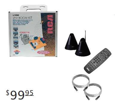 D940EXP 2nd Room KitWith one digital satellite system, use the D940EXP 2nd Room Kit to view the same programming in another room. And, control your receiver with the Universal Remote included in the kit. Easy to install, your kit includes all the necessary hardware: Signal Sender System – Converts infrared (line of sight) signal into radio frequency (goes through walls). Digital Satellite System Universal Remote – Keep your original remote with your Digital Satellite Receiver and use this remote in the 2nd Room. Preprogrammed to work your receiver and 4 additional components. 100 ft. Coaxial Cable – Used to run from your Digital Satellite Receiver to your 2nd Room TV. 3 ft. Coaxial Cable and Two-Way Splitter – Used to connect your primary and secondary TVs to your receiver.
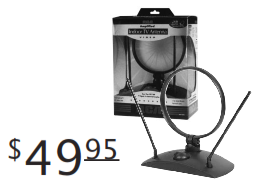 ANT200 Amplified TV AntennaConnect your Digital Satellite System Receiver to the ANT200 Amplified Antenna and begin receiving your local network stations. The built-in A/B switch makes it easy to switch between satellite stations and your local programs. With its unique design, you can boost your UHF/VHF TV signals for improved broadcast reception.
 D916 Wireless Phone Jack SystemThis handy device lets you turn any electrical outlet into a phone jack instantly. Use it to make the telephone connection to your Digital Satellite System Receiver. Easy to install in just minutes!
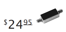
D903 In-Line AmplifierAmplifies incoming signal for best picture when installation requires long coaxial cable runs. (For Indoor Use Only)
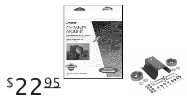
D915 CHIMNEY MOUNTMade of durable steel, the D915 Chimney Mount allows you to mount your Digital Satellite System to any size chimney.
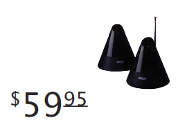
D940 REMOTE CONTROL SIGNAL SENDERControl your Digital Satellite Receiver from any room. Just plug it in! The Remote Control Signal Sender transmits your remote control signal from one room to another – through walls and floors. Extends the range of your remote control up to 140 feet. Also works most VCRs and Laserdisc Players from anywhere in your home. Contains one base unit and one extension unit. Each unit is only four inches tall. Additional extension units are available (Model #D935).
Accessory Order Form
To order accessories, contact your local Dealer. If a dealer is not nearby, you can also follow the directions below to order by telephone or by direct mail.
To place your order by phone, have your VISA, MasterCard or Discover Card ready and call the tollfree number listed below between 8:00 am and 10:00 pm (EST), Monday thru Friday, or 9:00 am and 5:00 pm (EST), Saturday. USE THIS number only to place an order for the accessories listed on this order form.
1-800-338-0376
To place an order by mail, detach and mail the completed order form with credit card information, check or money order (in U.S currency), made payable to Thomson Consumer Electronics, Inc., to the following address.
Video AccessoriesP.O. Box 8419Ronks, PA 17573
| DESCRIPTION | PART NO. | PRICE | QTY. | TOTAL |
| 2nd Room Kit | D940EXP | 99.95 | ||
| Chimney Mount | D915 | 22.95 | ||
| Amplified Antenna | ANT200 | 49.95 | ||
| Wireless Phone Jack System | D916 | 79.95 | ||
| In-Line Amplifier | D903 | 24.95 | ||
| Remote Control Signal Sender | D940 | 59.95 | ||
| Remote Control Signal Sender Extension Unit | D935 | 39.95 | ||
| TOTAL MERCHANDISE | ||||
| SALES TAX
We are required by law to collect the appropriate sales tax for each individual state, country, and locality to which the merchandise is being sent. |
||||
| SHIPPING AND HANDLING | 5.00 | |||
| TOTAL AMOUNT ENCLOSED |
Use VISA, MasterCard or Discover Card. Money Order or check must be in U.S currency only. No COD or cash.PRICES SUBJECT TO CHANGE WITHOUT NOTICEPlease Allow 4 – 6 Weeks For Delivery
Name:__________________________________________________________________________________ Address:________________________________________________________________________________City:________________________________________ Zip Code:___________________________________❑ Visa ❑ MasterCard ❑ Discover
Credit Card Number: _______________________________ Expiration Date:_________________________Signature: (Required for Credit Card Orders)____________________________________________________
Preparing for Installation
There are a few tasks you need to complete before you will be ready to mount the satellite dish, the most important of which is to make sure you have a clear line of sight to the satellite.
Installation Overview
The manual is organized into steps that need to be performed in the order presented.
Preparing for Installation
- Complete a General Site Survey – Visually survey your location to make sure it is suitable.
- Obtain Dish Pointing Coordinates – Use the on-screen menu system to obtain the exact coordinates (azimuth and elevation) for pointing the dish. Directions for using on-screen menus can be found in your receiver manual.
- Select the Precise Mounting Site – Use the dish pointing coordinates to conduct a precise site survey to determine the exact mounting site.
- Estimate Cable Requirements – Based on your mounting site, you will decide where you want the cable to enter your house, and measure how many feet of cables you need to complete the connection.
- Begin Dish Assembly – Attach the reflector to the support arm so that you can preset the correct elevation.
- Set the Elevation on Dish – This is an important step . Making sure that your elevation setting is correct will help you to more easily obtain the signal later on.
Mounting the Mast
- Mount the Mast – Step-by-Step mounting instructions for each mounting option.
Completing the Final Installation
- Level the Mast – The mast must be level to obtain the signal.
- Complete the Dish Assembly – Place the dish on the mast and connect the RG-6 coaxial cable to the LNB, and attach the LNB to the support arm.
- Route the Cables to the Grounding Block – Attach a grounding block to the house and route the cables from the dish to the grounding block. Also, route grounding wire from the grounding block to the central building ground.
- Run the Cables from Grounding Block into the House – Run the RG-6 cable from the grounding block into the house and to the back of the receiver.
- Make the Final Connections to the Receiver – Connect the RG-6 to the satellite input on the receiver, and make the phone line connection.
- Acquire and Fine-Tune the Satellite Signal – Use the on-screen signal meter to check for a signal. Once the signal is obtained, adjust dish pointing to achieve maximum signal strength for your location.
- Order Satellite Programming – Call the service providers to order satellite programming.
The Big Question: Should I Do This Myself?
While the installation is not difficult, it does require that you have some experience in electrical wiring and minor construction techniques. Also, you may have to climb a ladder, so you’ll want to be comfortable working with heights.
Question: Have you installed any of these home products or completed tasks similar to them?
- TV antenna outside your house
- ceiling fan
- basketball goal
- dimmer switch
- garage door opener
If the answer is YES, then you can be reasonably confident that you can install the Digital Satellite System yourself.
If the answer is NO, then this is probably not the time to learn. Consider contacting your local authorized DSS® retailer to recommend a professional installer.
General Site Survey
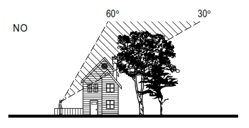
To get a signal, the satellite dish must be pointed directly at the satellite, with NO obstructions between the two. This means NO trees and NO buildings. Take into consideration future tree growth, house remodeling or additions and new construction in your area.
The satellite signal WILL NOT PASS through leaves or branches.
The satellite signal WILL NOT PASS through glass; don’t try to install your dish indoors!
Where Is The Satellite, Anyway?
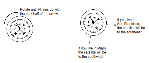
The satellite is always located south of Texas. That means if you live in Miami, you must have a clear line of sight to the southwest; if you live in San Francisco, you must have a clear line to the southeast.
How High Up in the Sky is the Satellite?
Depending on where you live, the satellite will be at an elevation angle between 30 and 60 degrees. Southern states point more toward 60 degrees; northern states point more toward 30 degrees.


Finding a Clear Line of Sight
- Go outside and locate at least one site on your property that has a clear view to the satellite. You should be reasonably certain you are pointing toward Texas (unless you’re in Texas, in which case you should be looking due south). You may want to use a map.
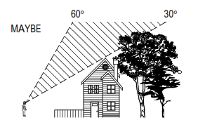
- Imagine an arc ranging from 30 to 60 degrees above the horizon.
- Do you have at least one clear view to the satellite? Remember, no trees, leaves, buildings, or windows can be between the dish and the satellite.If the answer is NO, your site may be unsuitable for installing the satellite system.If the answer is MAYBE, you may want to contact a your local digital satellite dealer for information about having a professional installer conduct a thorough site survey.If the answer is YES, your site should be suitable for installing the system. Go ahead to the next section in this manual.


Finding the Dish Pointing Coordinates
You need to connect the satellite receiver to your TV and use the on-screen menu system to find the dish pointing coordinates for your location.
Connecting the Receiver to a TV
For this task, you use the most basic connection to save time. After you have installed your system, you may want to consult the instruction manual that accompanies the receiver for more advanced connection options.
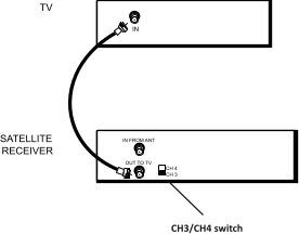
- Connect a coaxial cable to the OUT TO TV jack on the satellite receiver, and to the antenna IN jack on your TV.
- Make sure that the TV and the satellite receiver are both plugged into an AC power outlet.
- Turn on the TV and the satellite receiver.
- If the satellite receiver has a CH3/CH4 switch on the back, tune your TV to channel 3 or 4. If the satellite receiver does not have a CH3/CH4 switch, tune to UHF channel 14, or cable channel 65.
Additional InformationThis example shows a basic connection. Refer to the manual that accompanies the receiver for additional connection options.NOTEMake sure that you are connecting to the OUT TO TV jack on the receiver. Some models may have the outputs in different positions than shown in the diagram to the left.CAUTIONDo not stack electronic components on top of the digital satellite receiver.
Using the Dish Pointing Menu Screen
The satellite receiver has an on-screen menu feature for obtaining the precise dish pointing coordinates for your location. You can use the buttons on the front panel of the receiver to navigate through the menu system, or you can use the remote control. If you have not already inserted batteries into the remote, you can do that now.
Directions for using on-screen menus can be found in your receiver manual.
When you’ve obtained the coordinates, record the elevation and azimuth numbers below.
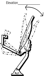
Elevation is the up/down angle that the dish is pointed
Azimuth ________________
Azimuth is side to side direction that the dish is pointed
Precise Site Survey
Based on your general site survey, you probably already know where you want to mount your dish, but it’s a good idea to follow the procedures outlined in this section in order to make sure that your site selection is a good one.
- Go outside to your install site and hold a compass flat in the palm of your hand. Hold your hand still until the needle stops moving (the dark or colored half of the compass needle always points north).
- Rotate the compass so that the “N” (for north) is directly under the dark part of the compass needle. Your compass is now aligned with north. The tick marks around the edge of the compass represent azimuth degrees.
- Locate the tick mark on the compass that corresponds to the azimuth number you wrote down. This is the direction of your azimuth setting (the direction the dish will need to be pointed to receive signals from the satellite).
- Raise your arm to approximately the elevation angle recorded earlier to make sure that there are no obstructions in the signal path.
- Repeat this survey in several places on your property if necessary until you find the best mounting location.TipTry to keep the compass away from any metal objects. Metal objects can cause inaccurate compass readings.WARNINGDo NOT install the dish near power lines, electric lights or power circuits. Contact with power lines, lights or power circuits may be fatal. It is recommended that the dish be located more than 20 feet from overhead power lines.

A Final Site SurveyNow that you’ve conducted a precise site survey using the dish pointing coordinates for your location, you should double-check one more time to make sure you have a clear view to the satellite.
I Don’t have a clear view to the satellite.If you don’t have a clear view to the satellite, then your site may not be suitable for installing the satellite system. A professional installer may have an alternative solution— consider contacting your satellite system dealer to find the name of an authorized satellite system installer.
 I’m Not sure If I have a Clear ViewIf you’re not certain whether you have a clear view to the satellite, you have two choices :
- Continue with the installation and determine whether you have a clear view to the satellite by testing the system.
- Contact your satellite system dealer to find the name of an authorized satellite system installer who can help you verify that your property is suitable for installation.
I Have A Clear View to the SatelliteYour site should be suitable for installing the satellite system.Continue with the installation.
Estimating Cable Requirements
Now that you’ve decided on the exact mounting site, you need to decide where you want the cable to enter the house, and then figure out approximately how much cable you are going to need.
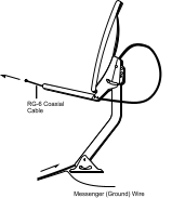
The diagram below shows you a “typical” installation scheme, outlining the cables that are needed. The information on the following page takes you through the cable estimating process step-by-step.
A Few Words About Grounding the System
Grounding the satellite system to the central building ground helps protect it and other components from lightning damage. Dish installation should comply with local codes and the National Electrical Code (NEC). Grounding the satellite system is something you can probably do yourself. But if you’re not sure, you should contact a qualified electrician.
Cable Estimate Procedure
- Locate the central building ground. You will ground the dish (via the cable grounding block) to a single point in the central building ground. The following is a list of acceptable building ground points:
- Grounded interior metal cold water pipe within five feet of the point where it enters the building.
- Grounded metallic service raceway.
- Grounded electrical service equipment enclosure.
- Eight-foot grounding rod driven into the ground (only if bonded to the central building ground by #6 or heavier bonding wire).
- Other acceptable grounding electrodes that comply with sections 250 and 810 of the National Electrical Code (NEC).
- Choose a location to mount the grounding block. The block should be as close as possible to the point where the cable will enter the house.
- Decide where inside the house you plan to put the satellite receiver.
- Estimate the amount of cable you will need for each of the following:
- One (1) RG-6 coaxial cable with messenger (ground) wire to run from the dish to a grounding block for each LNB output. The grounding block should be located near the cable’s point of entry into the house.
Write that distance here: .
- One (1) RG-6 coaxial cable (per LNB output) to run from the grounding block to each satellite receiver.
Write that distance here: .
- Grounding wire (#10 copper or #8 aluminum) to run from the grounding block to the central building ground.
Write that distance here: .
TipIf you have a dual-output LNB and plan to connect your dish to two separate receivers, don’t forget to double the RG-6 cable estimate to the grounding block, and include a separate estimate from the grounding block to the second receiver.
NoteYou must use RG-6 coaxial cable from the satellite dish to the SATELLITE IN jack on the receiver. Other types of coaxial cable, such as those used for cable television ( RG-59) do not work for the digital satellite system.
NoteIf your total RG-6 coaxial cable length from the dish to the receiver is more than 112 feet, you may need additional installation component, such as a line amplifier, to compensate for the longer cable length.
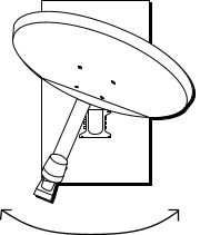
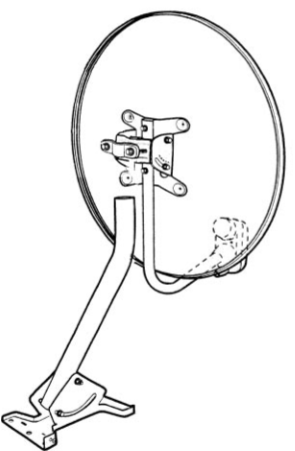
Dish Assembly Overview
Use this page both as a parts lists for your satellite antenna, and a general overview of how the parts fit together; but DON’T ASSEMBLE THE DISH YET.
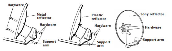
If your reflector looks like the one on the left, you should have. 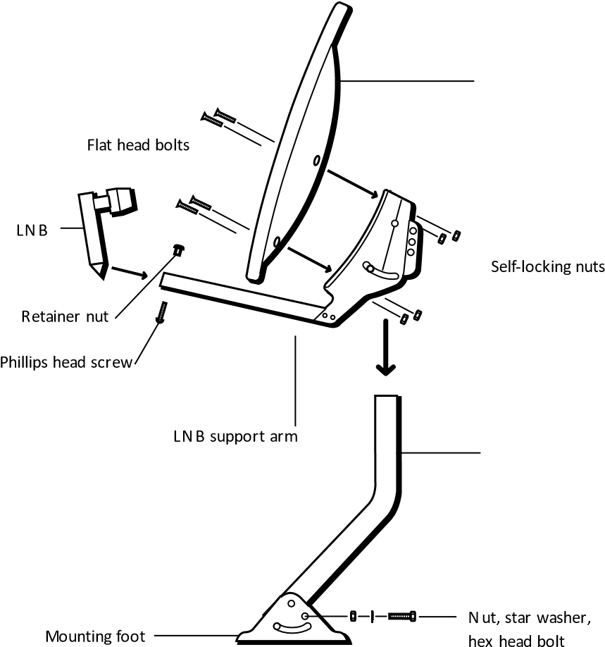
NoteIf you have a plastic reflector, the bolts are molded into the reflector; on metal reflectors, the bolts must be inserted through the holes on the reflector before attaching the reflector to the support arm.
If you have a Sony reflector, you should have:
- Mounting foot and mast
- Satellite dish reflector
- LNB (Low Noise Block converter) and LNB support arm
- Hardware packet

Partial Dish Assembly
- Locate the reflector, the support arm, and the hardware packet.
- Attach the reflector to the support arm :
- Metal Reflector: Pass the bolts through the reflector, and then place the reflector on the support arm by inserting the bolts through the holes on the support arm. Use a wrench to secure the four self-locking nuts.
- Plastic Reflector: Pass the four bolts molded into the back of the reflector through the four holes on the support arm. Place a star washer and nut on each of the bolts and secure each with a wrench.
- Sony Reflector: Align the screw holes on the LNB arm holes and reflector bracket holes. Screw in the machine screws,tightening the LNB support arm to the reflector bracket. Do not over-tighten.
Setting the Elevation on the Dish
After you have securely attached the reflector to the support arm, you need to set the dish to point up toward the satellite. This is called “setting the elevation.”
- Loosen the two elevation nuts so the support sleeve can rotate.
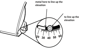
- Rotate the support sleeve so that the elevation indicator lines up with the tick mark corresponding to the elevation setting you recorded earlier.
- Tighten both nuts.
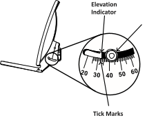
IMPORTANTMake sure that you use the elevation indicator and not the nut to line up the elevation. If your elevation is not correctly set, you won’t be able to obtain a signal.
Mounting the Mast
Now that you have selected your site, and estimated your cable needs, you need to select a mounting option and mount the mast.
Take a moment to look through the available options and select the one that best suits your installation site.
After you have selected a mounting option, and successfully mounted the mast, you can go on to the final section of this manual to complete the installation.
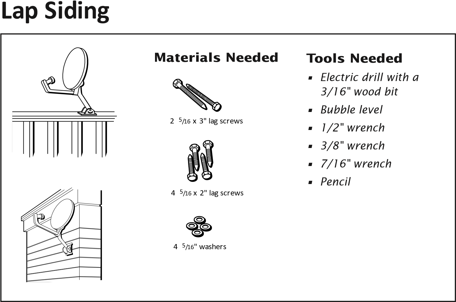
Mounting the Mast on Solid Wood or Lap Sidin
Important Considerations:
- Make sure the wooden surface is structurally sound
- Do NOT mount the dish where someone might use it as a handrail.
- Do NOT mount the dish on any type of aluminum or vinyl siding.
- Do NOT mount the dish on any type of composite paneling, such as fiberboard, particleboard, or strand board.
- Do NOT mount the dish under an eave or overhang that may block or partially shadow the dish.
DANGERAVOID Power Lines!When following these instructions, take extreme care to avoid contact with overhead power lines, electric lights, and power circuits. Contact with power lines, electric lights, or power circuits may be fatal. It is recommended that the dish be located more than 20 feet from overhead power lines.
Mounting Instructions
- Locate the center of a stud where you want to mount the mast foot. Make sure you locate and secure the mounting foot to the center of a wall stud. Do not mount the dish near the edge of a stud.
- Hold the mounting foot in a position so the center line is centered on a stud or solid wood surface.
- If you are mounting on a sloped or vertical surface, use a level to verify that the center line is perfectly vertical.

Step 2: Center the foot on the stud.
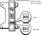
Step 3: Make sure the mounting foot is level.
- Use a pencil to mark the two center holes and the four outside corner holes of the mounting foot.
- Remove the mounting foot and drill two 3/16″ holes in the two center hole locations and four 3/16″ holes in the four outside corner locations.
- Use a wrench to loosen the nuts on the mounting foot so that you can rotate the mast to access both of the center mounting holes.
- Hold the mounting foot over the holes so that the top part of the mast will rotate and point straight up.


Step 7: Make sure that the top of the mast will point straight up.
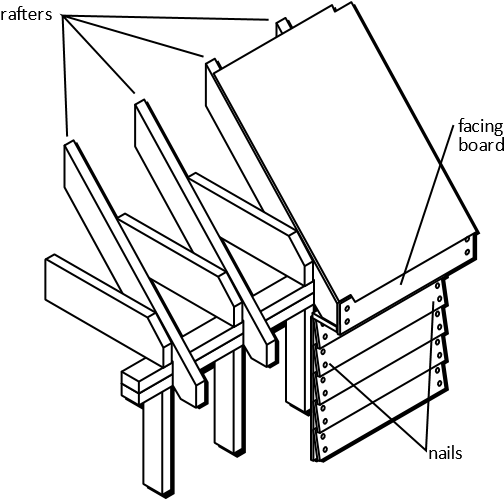
TipTo locate a stud underneath panel siding, locate the nails securing the panel to the wall. The nails usually align with the center of the stud and provide an easy guide.
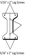
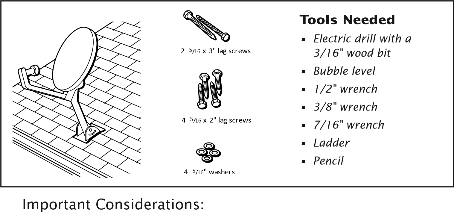
- Install two 5/16″ x 3″ lag screws into the two center holes on the mounting foot. Securely tighten the screws.
- Put washers on the 5/16″ x 2″ lag screws, insert the screws into the four outside holes and securely tighten them.5 /16″ x 3″ Lag Screws ( For Sony Dish Installations use (2) 3″ x 1/4″ Lag Screws)Steps 8 & 9: Inserting the lag screws.
- Go on to the next section, “Final Installation,” to complete the installation process.
 5 /16″ x 3″ Lag Screws ( For Sony Dish Installations use (2) 3″ x 1/4″ Lag Screws)Steps 8 & 9:
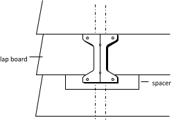
 Installing a Spacer
When the mounting foot spans two pieces of siding, it should be positioned so most of the foot is on the top board. A spacer should be installed to help hold the bottom of mounting foot in place. The spacer can be made of either solid wood or plastic.
Mounting the Mast on Brick or Poured Concrete
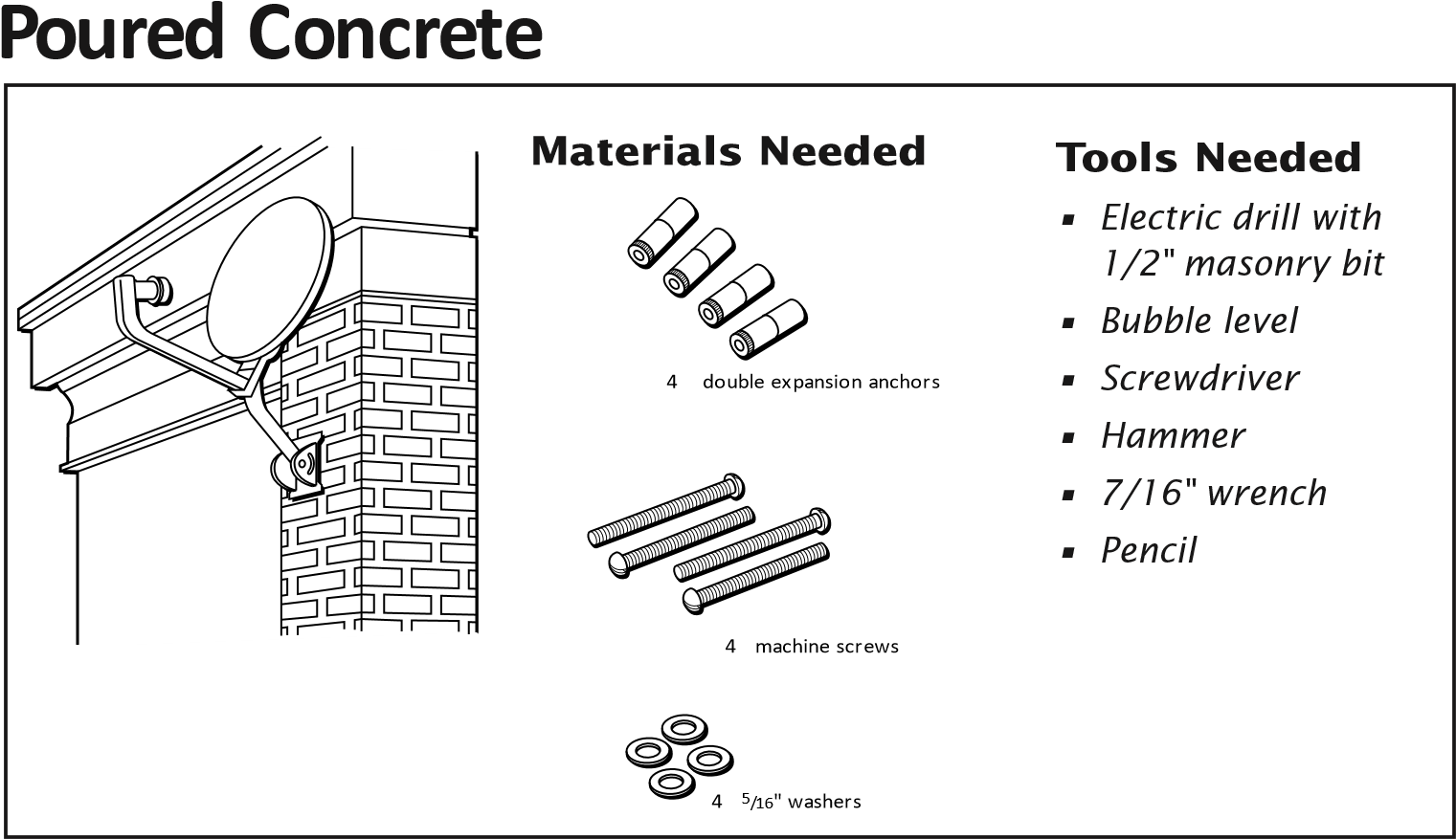
IMPORTANT Considerations
- The wall anchors used must have a strength of at least 300 pounds of pull-out pressure. B4015 or equivalent doubleexpansion anchors are recommended.
- Do NOT mount the dish under an eave or overhang that may block or partially shadow the dish.
Mounting Instructions
- Hold the mounting foot in position on the mounting surface.
- If you are mounting on a vertical or sloped surface, use a level to DANGER ensure that the center line is vertical.Step 1: Hold the mounting foot in position.Step 2: Make sure the mounting foot is level.
- Mark the four outside holes on the mounting foot.
- Remove the foot and drill four (4) 1/2″ holes in the locations you marked
- Insert four (4) double-expansion anchors.
- Use a wrench to loosen the nuts on the mounting foot so you have easier access to the mounting holes.
- Hold the mounting foot over the holes so the top part of the mast will rotate and point straight up. Step 7: Make sure that the top of the mast will point straight up.
- Insert and tighten the machine screws.
- Go on to the next section, “Final Installation,” to complete the installation process.DANGERAVOID Power Lines! When following these instructions, take extreme care to avoid contact with overhead power lines, electric lights, and power circuits. Contact with power lines, electric lights, or power circuits may be fatal. It is recommended that the dish be located more than 20 feet from overhead power lines.
 Step 1:
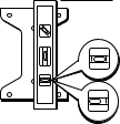

 Step 7:
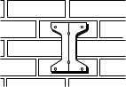
 Mounting the Mast on a Hollow or Cinder Block Wall
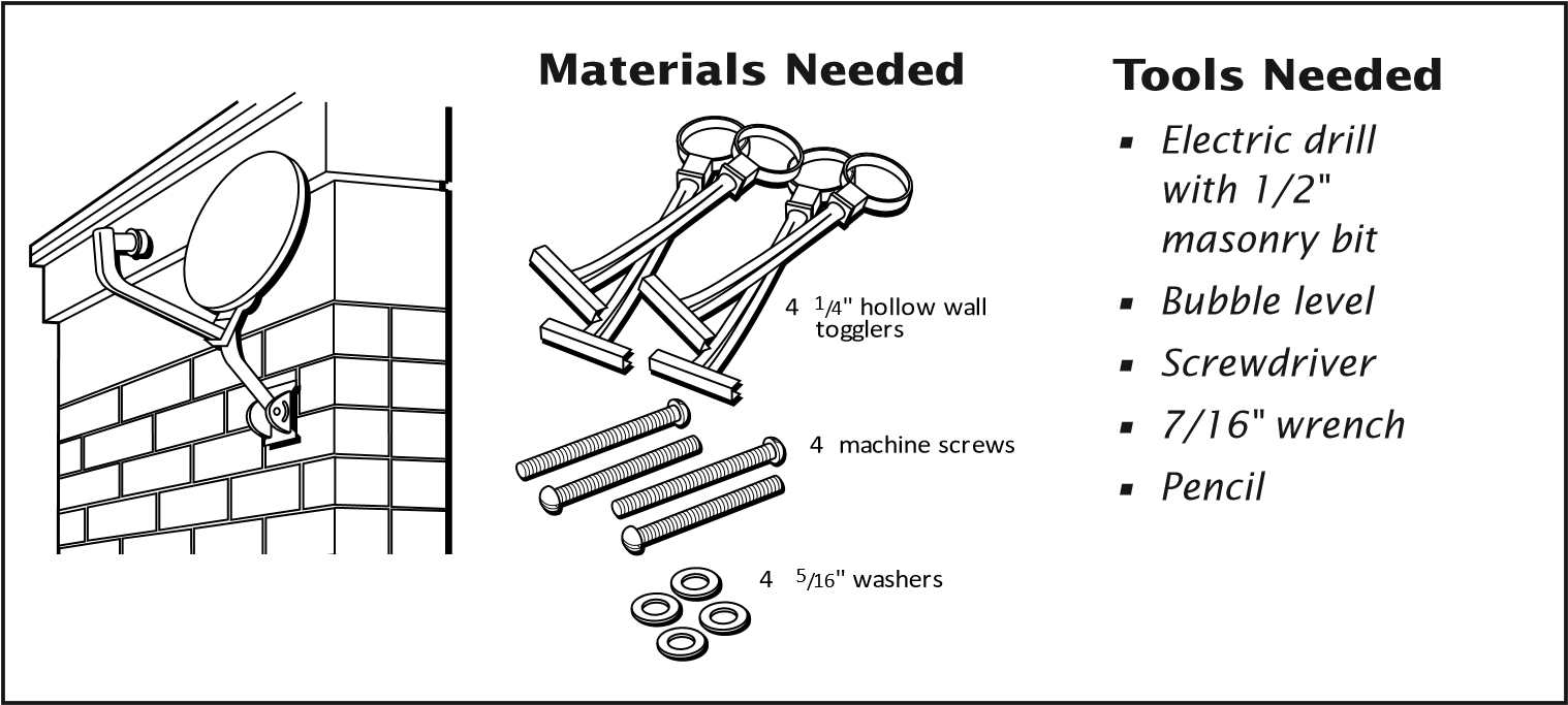
IMPORTANT Considerations
• Do NOT mount the dish under an eave or overhang that may block or partially shadow the dish.
Mounting Instructions
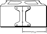
- When installing togglers in cinder blocks, it is important to position them in the core of the block. To position the foot on the wall, measure 7-1/2″ from one edge of the block and mark the center of the block.
- Center the mounting foot on the mark you made.
- Level the centerline of the mounting foot using a bubble level.
- Mark the four outside corner holes.
- Remove the mounting foot. Drill a 1/2″ hole at the marked locations.
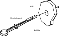
- Install the togglers:a. Carefully fold one end of the metal channel along the plastic straps. Hold the metal channel flat against the plastic straps and slide it through the hole.Step 6a: Slide the metal channel through the hole.b. Pull the ring so the metal channel rests flush behind the wall. Hold the ring tight and slide the plastic cap along the straps until the cap is flush with the wall.Step 6b: Make sure the plastic cap is flush with the wall.c. Push the straps side-to-side to snap them off flush with the wall.Step 6c: Snap off straps flush with the wall.d. Repeat for all four holes.
- Use a wrench to loosen the nuts on the mounting foot so you have easier access to the mounting holes.Step 8: Make sure that the top of the mast will point straight up.
 Step 6a:
 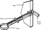 Step 6b:

- Hold the mounting foot over the holes so the top part of the mast will rotate and point straight up.
- Place washers on each of four #20, 1/4″ x 3″ machine screws and attach the mounting foot to the wall. Securely tighten the screws.
- 10 .Go on to the next section, “Final Installation,” to complete the installation process.
DANGERAVOID Power Lines!When following these instructions, take extreme care to avoid contact with overhead power lines, electric lights, and power circuits. Contact with power lines, electric lights, or power circuits may be fatal. It is recommended that the dish be located more than 20 feet from overhead power lines.
Mounting the Dish on a Pole
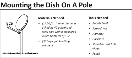
Important Considerations:
- Do not install the pole in wet or marshy areas.
- The pole must go at least 3 feet below the surface.
- If the length of pipe above ground is too long, guy wires may be needed to increase the stability of the mount in windy conditions.
- You will need to ground the pole in addition to the dish and coaxial cable.
- The pole that has been secured in the ground with concrete replaces the mounting foot and mast assembly that was supplied with the dish. The dish is held on the pole by the sleeve of the LNB support arm.
Mounting Instructions
- Dig a hole 36″ deep and 8″ to 12″ wide at the mounting location. The depth of the hole must extend at least 6″ below the frost line. For most installations, a pole 6′ long is sufficient, since this allows 3′ of the pole to be below the ground and 3′ above ground.
- Use a hacksaw to cut a 45o angle at the bottom of the pole. This will prevent the pole from rotating in the concrete over time.
- Place the pole in the hole and use a small amount of dirt or stones to hold the pole upright. You need to attach guy wires to help keep the pole upright.
- Level the pole using the bubble level. Level the pole at two different locations that are at right angles to each other.Top view of polePut level in 2 places at right angles to each other
- Fill the hole with quick-drying cement. Stop when the
- Let the cement completely dry before you mount the dish on the pole.
- Go on to the next section, “Final Installation,” to complete the installation process.

 Put level in 2 places at right angles to each other
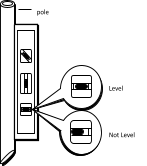
DANGERAVOID Power Lines!When following these instructions, take extreme care to avoid contact with overhead power lines, electric lights, and power circuits. Contact with power lines, electric lights, or power circuits may be fatal. It is recommended that the dish be located more than 20 feet from overhead power lines.
Mounting the Mast on a Roof
IMPORTANT
Use the roof mount only as a last resort. You can easily damage the roof by walking on it or cause leaks by not properly sealing the mounting holes. Problems with roof installations increase with the age of the roof and the type of roofing materials.
- Do not mount the dish on slate or shake shingles.
- Do not mount the dish on an overhang.
- On a flat roof, do not mount the dish in a place where water collects.
Step-by-step Instructions for Mounting the Maston a Roof
- Locate the center of a rafter where you want to place the mounting foot.Step-1: Locate where you want the mounting foot to be placed.
- Hold the mounting foot in a position so the centerline is centered on a rafter.
- Use a bubble level to make sure the center line is perfectly vertical.Steps 2 & 3: Center the mounting on a rafter and make sure that it is level.
- Use a pencil to mark the six holes in the mounting foot.
- Remove the mounting foot and drill a 3/16″ hole in the two center line locations you marked.
- Drill four 3/16″ holes in the four outside corner locations you marked.
- Fill all six holes with a small amount of roof sealant.
- Use a wrench to loosen the nuts on the mounting foot so you have easier access to the mounting holes.
- Hold the mounting foot over the holes so the top part of the mast will rotate and point straight up.
- Use two 5/16″ x 3″ lag screws in each of the center line holes to attach the mounting foot to the roof. Secure the four outside corner holes with four 1/4″ x 2″ lag screws. Securely tighten all six screws.
- Seal the mounting foot with roof sealant. When applying the sealant, make sure you seal the areas shown in the figure below.Step 9: Make sure the top part of the mast points straight up.Step 11: Seal the mounting foot to avoid water leakage.
- Go on to the next section, “Final Installation,” to complete the installation process.DANGERAVOID Power Lines!When following these instructions, take extreme care to avoid contact with overhead power lines, electric lights, and power circuits. Contact with power lines, electric lights, or power circuits may be fatal. It is recommended that the dish be located more than 20 feet from overhead power lines.
 Step-1: Locate where you want the mounting foot to be placed.
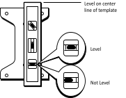 Steps 2 & 3:
  Step 9:
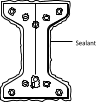
Final Installation
This section contains the final steps necessary to get the signal from the satellite dish to your satellite receiver.
Leveling the Mast
Leveling the mast is one of the most important steps in installation. If the mast is not level, the elevation and azimuth settings will not be accurate. This will make it difficult to obtain the satellite signal.
The mast must be level in both the side-to-side and the front-to-back directions. Side-to-side leveling determines whether the mounting foot is level. Front-to-back leveling determines whether the mast is level.
Leveling Side-to-Side
- If you mounted the mast on a vertical surface , such as a wall, you leveled the mast side-to-side when you mounted the mast foot. Skip to “Leveling Front-to-Back” on the next page.
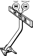
- To check whether the mast is level side-to-side, place a bubble level on the mast as shown in the figure below.
- Is the bubble centered in the level’s window?If YES — Continue to “Leveling Front-to-Back”.If NO —a) If the bubble is not centered, determine which side of the mounting foot needs to be raised.b) Unscrew the lag or machine screws from that side of the mounting foot.c) Place washers between the mounting foot and the mounting surface. Use enough washers to level the mounting foot.d) Secure the mounting foot with the lag or machine screws.Step 2: Verify that the mast is level side-to-side.Step 3: If the mast is not level, add washers to level the foot.CAUTIONUse caution when installing, adjusting or dismantling the dish and mast. The weight of the dish may cause the dish and mast to swing down and strike you, a bystander or nearby objects. This could cause personal injury or damage to the dish. Never insert your fingers inside the mast. Always grip the mast around its outside circumference.
 Step 3
Leveling Front-to-Back
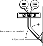
- Loosen the two bolts securing the mast to the mounting foot so the mast moves freely.
- Place a bubble level on the mast as shown in the figure. Move the mast so the bubble is centered in the level’s window.Step 2: Verify that the mast is level front-to-back.
- Tighten the two bolts securing the mast to the mounting foot.
 Step 2:
 Final Dish Assembly
- Place the dish-LNB arm assembly on top of the mast (or pole).Step 1: Place the dish assembly on the mast or poleSony Step 1:Loosen the mast clamp and lower reflector onto the mast. Tighten the clamp screws.
- Find the length of RG-6 coaxial cable with messenger (ground) wire that will extend from the satellite dish to the cable’s point of entry into the building.If your total RG-6 coaxial cable length from the dish to the receiver is more than 112 feet, you may need an additional installation component, such as a line amplifier, to compensate for the longer cable length.
- Separate the messenger (ground) wire from the coaxial cable. Separate only the amount required to install the coaxial cable through the LNB arm. (Sony dish owners skip to next step.) Push only the coaxial cable through the bottom of the mast and out the top. Pull about 2 feet of cable out of the top. Loop the cable and push it through the LNB support arm as shown below.
- Place some silicone grease on the LNB connector and connect the end of the coaxial cable to the LNB. (Sony dish owners: clip the coaxial cable to the LNB arm and skip to step 8.)Step 3: Route the cable through the mast.Step 4: Connect the coaxial cable to the LNB.
- Insert the end of the LNB into the end of the LNB support arm (push any extra coaxial cable back through the support arm).
- Locate the special hex retainer nut and insert it into the LNB mounting hole on top of the LNB support arm.
- Locate the phillips head screw and insert it into the LNB mounting hole from the bottom of the LNB support arm. Tighten the screw with a screwdriver
- Locate the grounding hardware (bolt, star washer and nut).
- Insert the bolt as shown below and attach the messenger (ground) wire to the foot of the mast (you may want to trim the extra messenger wire before attaching). You will connect the other end of that wire to the grounding block at the building entry point.Steps 5-7: Secure the LNB to support. Step 9: Attach the messenger (ground) wire to the mast foot with the nut, star washer and bolt.


TipIf you have a dual-output LNB, and are planning to connect your dish to two separate receivers, you should route both cables at this time.
TipThe hex retainer nut must be inserted into the top of LNB before the phillips head screw is inserted into the bottom of the LNB. Otherwise it is very difficult to thread the screw to the nut.
NoteWhen using a pole mount, you need to attach the grounding wire to the metal pole using a 1 1/2” grounding clamp.
A Few Words About Grounding the System
Grounding the satellite system to the central building ground helps protect it and other components from lightning damage. Different brands of satellite systems may have special grounding requirements. However, dish installation should comply with local codes and the National Electrical Code (NEC). Refer to your satellite system’s user guides for any other additional grounding information. Grounding the satellite system is something you can probably do yourself. But if you’re not sure, you should contact a qualified electrician.
Acceptable central building ground points
- Grounded interior metal cold water pipe within five feet of the point where it enters the building.
- Grounded metallic service raceway.
- Grounded electrical service equipment enclosure.
- Eight-foot grounding rod driven into the ground (only if bonded to the central building ground by #6 or heavier bonding wire).
- Other acceptable grounding electrodes that comply with sections 250 and 810 of the National Electrical Code (NEC ).
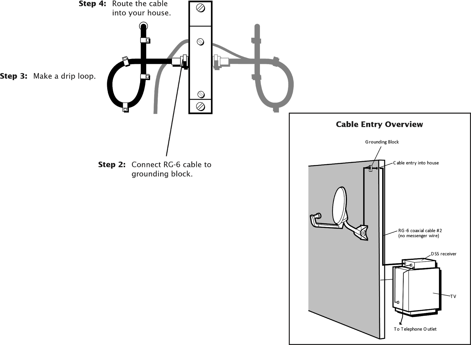
Routing and Grounding the Cables
- Attach the grounding block to the side of your house close to the point you have chosen as the coaxial cable entry point. You may have to use anchors, togglers, or wood screws depending on the surface on which you are mounting the grounding block.Step 1: Attach the grounding block to side of your house at your designated entry point.
 Step 1:
 - Route the coaxial cable and messenger (ground) wire from the bottom of the mast to the grounding block.
- Make a 3”- 5” drip loop using cable clips at the grounding block as shown. This will prevent water from running into the connection at the grounding block.
- Place some silicone grease on the connector and connect the coaxial cable to the grounding block
- Secure the messenger (ground) wire to the grounding block,.
- Locate the central building ground (see the list of acceptable central building grounds on the preceding page).
- Locate the grounding wire (#10 copper or #8 aluminum) that will extend from the grounding block to the central building ground. Attach the grounding wire to the grounding block by placing it through the wire hole in the grounding block and tightening the screw.
- Route the grounding wire from the grounding block to the central building ground, and connect to the central building ground.IMPORTANTThe United StatesNational Electrical Code specifies that coaxial cable that is exposed to lightning shall be connected to the grounding system of the building as close to the point of cable entry as possible.CAUTIONIt is extremely important to ground the dish AND the coaxial cables to a single point in the central building ground. A nearby lightning strike can easily damage an ungrounded dish, the receiver and your TV. Connecting both ground wires to the same point in the central building ground meets code requirements and provides the best protection for your equipment.Cable Routing Tips• If you are routing the grounding wire along the ground, make sure the wire is buried deep enough so that it will not be damaged or uncovered.• If you are routing the wire or cable above the ground, use cable clips to secure the two to a wall or surface.• Make sure you route the grounding wire in an area where people or animals are not likely to come in contact with the cable.

Running Cable Into the House
- Drill a hole in the location you want the coaxial cable to enter.
- Place some silicone grease on the connector and connect the RG-6 coaxial cable that will extend from the grounding block to the receiver.
- Make a 3” – 5” drip loop using cable clips at the grounding block.
- Route the coaxial cable through your house to the back of the receiver. You may route the coaxial cable through a floor or wall or directly to the back of the receiver. If you are routing through a wall, you may choose to install a wall plate at the point the coaxial cable enters the inside of the house and use a third RG-6 coaxial cable.
- Use a silicone sealant to seal all outside connections and the hole you drilled for the coaxial cable to enter your house.CAUTIONBefore drilling, make sure there are no wires or pipes behind the wall in the area of the hole.
 CAUTION
Making the Final Connections
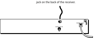
- Connect the RG-6 coaxial cable to the SATELLITE IN jack at the back of the receiver as shown. DO NOT connect the coaxial cable to the IN FROM ANTENNA jack!
- Take a phone off the hook to prevent electric shock from incoming calls.
- Connect a phone cord from the back of the receiver to a phone jack.Step 1: Connect the RG-6 cable to the SATELLITE INStep 2 & 3: Take the phone off the hook before you connect a phone cord from an outlet to the back of the receiver.About the PhoneConnectionThe satellite receiver calls a telephone number once a month or so to update your access card. It is also used to order pay-per-view events. These calls only take a few seconds.
 Step 2 & 3:
 Acquiring and Fine Tuning the Signal
Now that you have installed the satellite antenna and routed all of the cable, it’s time to acquire and fine tune the signal. Before you begin, you may want to go outside and double-check the azimuth and elevation settings on the dish.
- Make sure that the elevation indicator (the edge of metal, not the washer or the bolt) is aligned to the correct elevation.
- Use a compass to verify that the azimuth setting on the dish is correct.
When you are confident that the settings are correct, bring up the “Dish Pointing” menu again and use the signal meter to see if you are getting a signal. Once you have acquired the signal, you’ll want to make some fine-tuning adjustment to the dish in order to obtain the highest possible signal.
Refer to your receiver manual for dish pointing information.
If you are not receiving a signal, you need to incrementally adjust the azimuth setting on the dish. After you receive a signal, you will want to continue to adjust the azimuth to try to get the best possible signal.
Maximum Signal StrengthWhile the maximum signal strength is 100, the signal strength you achieve will probably be less. Although there is no difference in picture quality between a signal strength of 60 and 85 , the higher the signal, the less likely you are to experience signal outages during adverse weather.
TipYou can adjust your TV’s volume to hear the signal meter from the dish location, or you may want a friend to watch the signal meter and relay the strength to you.
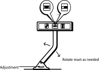
Adjusting the Azimuth and Elevation Settings
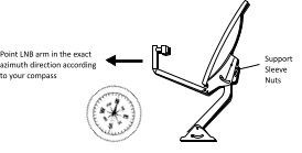
- Using a compass, rotate the dish so that the LNB arm points to the correct azimuth heading. Loosen the support sleeve nuts as needed. (Sony dish owners loosen the mast clamp screws.)
- If you do not hear a continuous tone from the signal meter, use the following procedure to adjust the dish until you hear one continuous tone:
- At the top of the mast is a piece of tape with evenly spaced tick marks. Carefully rotate the dish one tick mark to the right and pause for 3-5 seconds.
- If you do not hear a continuous tone, rotateLine edge of bracket up with tick marks the dish back to the original position and then one tick mark to the left and pause for 3-5 seconds.


- Continue rotating the dish one tick mark at a time further right and left from center (making sure to pause for 3-5 seconds at each position) until you hear the continuous tone, and the highest signal meter reading.
- After you get a signal, continue adjusting the azimuth by rotating the dish in small increments left and right until you achieve the highest possible strength.
- Tighten the support sleeve nuts so the dish won’t rotate left and right.
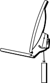
- Slightly loosen the elevation nuts on the LNB support arm so you can adjust the dish up and down.
- Adjust the elevation of the dish upward and downward until you achieve the highest possible signal strength:
- Move the dish upward one tick mark, pause for 5 seconds, and check the signal strength.
- Move the dish downward (back to the original elevation setting) and then move down one tick mark, pause for five seconds, and check the signal strength.


- When you achieved what you believe to be the highest signal strength (peak signal), tighten the elevation nuts on the support arm.ElevationAdjustmentWhen setting the elevation, be sure to line up the elevation setting with the elevation indicator and not the bolt.
Ordering Programming
After you have obtained and fine tuned the satellite signal, the last step you need to complete is to call the program providers to order programming, and then review the satellite receiver’s instruction manual for information about using all of the great features it offers.
Troubleshooting
Can’t Pick Up the Satellite Signal
Most problems with signal acquisition can be traced to one of these points: improper cabling and connections or inaccurate positioning and pointing of the dish.
Cabling and Connections Problems
- Make sure you’re using the proper type of RG-6 coaxial cable to connect the LNB to the grounding block and the grounding block to the satellite receiver. Standard Cable TV coaxial cables (RG-59) will NOT pass the satellite signals properly. Important: Do NOT connect the RG-6 cable from the dish or grounding block to any existing TV cable in your house. Do not use conventional TV splitters. They will not pass the satellite signals.
- Make sure the access card is fully inserted into the access card slot.
- Check all cable connections to make sure they are securely fastened to the proper connectors, from the TV, to the satellite receiver, all the way out to the dish LNB. Make sure the coaxial cable connector center conductor is not bent or broken.
- Make sure the cable from the dish to the receiver is connected to the SATELLITE IN jack on the back of the receiver (NOT the ANTENNA IN jack).
Dish Positioning and Pointing Problems
- Verify that you are using the correct azimuth and elevation for your city by using the dish pointing menu.
- Make sure the dish is physically set to the correct elevation according to the dish pointing menu.• Make sure the dish mast is level.• Make sure the elevation indicator (edge of metal, NOT the washer or the bolt) is aligned to the correct elevation.
- Use a compass to verify that the LNB support arm is pointed toward the correct azimuth reading (number) as indicated by the dish pointing menu. Nearby metal objects may cause a compass to give an inaccurate reading.
- Make sure there are no obstructions (trees, buildings, windows, your body or hands, etc.) that might be blocking the satellite signal.
- Slowly rotate the dish left or right (one tick mark at a time) pausing at each for 3-5 seconds until the on-screen signal meter produces one continuous tone.
- If you can’t acquire a signal by rotating the dish left and right, readjust the elevation of the dish.• Return the LNB support arm to the original azimuth (left-to-right compass direction).• Loosen the elevation nuts on the LNB support arm and position the dish upward or downward (one tick mark at a time). When finished, retighten the nut.
Temporary Satellite Signal Loss
If you lose the satellite signal temporarily, the problem can usually be traced to one of these points:
- Rain Fade. Rain fade is a normal, temporary loss of a satellite signal due to the inability of the satellite signal to penetrate unusually heavy, rain-filled clouds, rainfall, or snowfall. Rain fade tends to be brief, lasting only as long as the heavy cloud condition persists.To minimize rain fade effects, maximize your signal strength. Then, when rain fade occurs, you have the best chances of having a signal that is still strong enough to view.Make sure the dish is mounted securely. The strong winds that often accompany heavy rainstorms can move the dish out of position if it is not mounted securely.Also, heavy/wet snow and ice build up on the dish can block the satellite signal until the build up is removed.
- Overheated Components. The satellite receiver must receive adequate ventilation to work safely and properly. If the receiver overheats, the satellite signal may deteriorate until adequate ventilation is restored. Do not stack VCRs or other components on top of the satellite receiver.
You hear a dialing sound while talking on the phone( If the Satellite Receiver is Connected to a Phone Line )
Your satellite receiver may be attempting to call the billing center. Under normal conditions, the receiver hangs up any time it detects what it interprets as a voice on the line. After four unsuccessful attempts to get a dial tone, the receiver is designed to call out regardless of the status of the line. If you’re using the phone when the receiver calls out, you’ll hear a dialing sound. Don’t worry: your phone connection will not be broken.
Dish Pointing Steps
- Step 1: Are you receiving a signal?•If yes, go to Step 4.•If no, proceed to Step 2.
- Step 2: Adjust the azimuth right or left. Are you now receiving a signal?•If yes, go to Step 4.•If no, proceed to Step 3.
- Step 3: Adjust the elevation up or down 1 tick. Are you now receiving a signal?•If yes, proceed to Step 4.•If no, return to Step 1.
- Step 4: Carefully adjust the azimuth (left or right) and the elevation (up or down) until the peak signal is achieved. When finished, tighten the azimuth and elevation bolts.
Digital Satellite System Installer’s Reference
Thomson Consumer Electronics (Digital Satellite Systems)
Support Line
Digital Satellite System Service Support Line 1-800-679-4776Call this number to resolve service and use and care questions.
Program Providers
DIRECTV
Customer Service 1-800-347-3288Use this number to resolve programming and billing inquiries and to deactivate service.
Installer Activation 1-800-277-4388Use this number to activate a newly installed system.
USSB
Customer Service 1-800-204-8772Use this number to resolve programming and billing inquiries and to deactivate service.
Installer Activation 1-800-883-8772Use this number to activate a newly installed system.
Digital Satellite System Publications
Publication/Description
New Home “Prewiring” & Distribution Systems Accessories and Antenna Components CatalogTo obtain the publications listed above contact:Thomson Consumer Electronics10003 Bunsen WayLouisville, KY 40299Telephone: 502-491-8110
Publication numberT-DSSPREWIRE-1T-8743CM
Index
| A | M |
| Acceptable central building ground points 31 | Mast, leveling 28 |
| Acquiring the satellite signal 35 | Messenger (ground) wire 30 |
| Azimuth setting, adjusting 36 | Metal dish putting together 14 |
| C | Mounting options Brick or poured concrete 19 |
| Cable, routing into the house 33 | Hollow or cinder block wass 20 |
| through the mast 30 | Pole mount 23 |
| Central building ground 11, 31 | Roof 25 |
| acceptable points 31 | Solid wood or lap siding 16 |
| CH3/CH4 switch 7 | N |
| Compass, using 9 | National Electrical Code (NEC) 11, 31 |
| Connecting the dish to the receiver 34 | P |
| D | Phone connection 34 |
| Dish, final assembly 29 | Plastic dish |
| Dish pointing steps 39 | putting together 14 |
| Double-expansion anchors 19 | Precise site survey 9 |
| Drip loop 32 | R |
| E | RG-6 coaxial cable drip loops 32 |
| Elevation setting 14 | routing into house 33 |
| Elevation angle 9 | Roof mount sealing the mounting foot 26 |
| Elevation nuts 14 | Roof mounting option considerations 25 |
| Elevation setting, adjusting 37 | S |
| F | Site survey 9 |
| Fine-tuning the satellite signal adjusting the azimuth 36 | Support sleeve 14 |
| G | T |
| Ground wire, separating 30 | Troubleshooting signal acquisition for system test 38 |
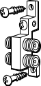
| Grounding block 12 | |
| Grounding the system house entry point 31 | |
| Grounding wire 32 | |
| L | |
| Lap siding mounting option use of a spacer 18 | |
| LNB attaching to the LNB support arm 30 | |
| connecting the RG-6 coaxial cable 30 |
![]() 10330 North Meridian StreetIndianapolis, IN 46290
10330 North Meridian StreetIndianapolis, IN 46290
©1998 Thomson Consumer Electronics, Inc.Trademark(s)® RegisteredMarca(s) Registrada(s)Printed in USATOCOM 15347490
Satellite Dish Antenna T-DSSPREWIRE-1 Self-Installer’s Guide – Satellite Dish Antenna T-DSSPREWIRE-1 Self-Installer’s Guide –
[xyz-ips snippet=”download-snippet”]