RCS TBH300 ZigBee Management Thermostat
Installation Guide
This thermostat is compatible with most HVAC systems, including the following:
- 24VAC systems Note: requires both the 24VAC R and C (“common”) wires.
- Standard gas/oil/electric heating systems
- 1 stage heating and cooling
- 2 stage heating and cooling
- Heat Pump systems:
- 1 stage heating and cooling
- 2 stage heating and cooling
- 2nd or 3rd stage Auxiliary heating (heat strips)
- Do NOT use for line voltage controls (120/240VAC)
The thermostat is powered by 24VAC.
24VAC Powered OperationPowering the thermostat with 24VAC power requires both the C wire (24VAC common wire – typically blue) and the R wire (24VAC hot wire – typically Red).
Installation Steps
- Remove old thermostat.
- Install TBH300
- Set up the thermostat for the HVAC system
Remove old thermostat
- Turn off power to the HVAC system. Usually at the HVAC system or the circuit breaker panel.
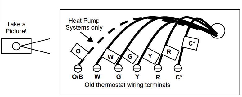
- Remove cover of old thermostat to expose the wiring terminals
- Take a picture of the wiring terminals! This will help with troubleshooting later if needed.
- Mark the wires attached to the terminals with the wiring labels included
- Use the terminal labels and not the wiring color to mark the wires
- Remove the old thermostat base
- Caution! Don’t let the wires slip into the wall.
*Note: the C wire (24V common) may not be present. If the C wire is present, you can power
Mark the wires according to the terminal markings. There may be additional wires such as Y2, W2 If you have RC and/or RH connections, see below. Other wires are not used,
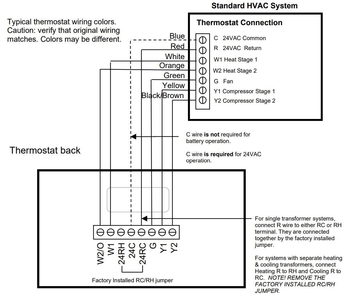
Wiring colors. While the wiring terminals markings are intended to match the wire color (R=Red, G=Green, W=White, Y=Yellow, O=Orange), not all installations were correctly installed this way. Be sure to follow the terminal marking when marking the wires, even if the wire color doesn’t match.
24VAC Power. The thermostat requires the 24VAC C (common) wire be connected to operate. Note that the 24VAC C common wire (usually Blue) may be present but not connect to 24VAC common at the HVAC system end.
Connect the wires – most common connections
Mount the thermostat base to the wall using the wall anchors and screws provided. Level as needed. Connect the wires according to the HVAC system type as below.
Standard Gas/Electric HVAC System WiringSingle stage heating and cooling

R vs RC and RH Connections: Single Transformer HVAC Systems. Typical modern central HVAC installations have a integrated heating and cooling system with a single 24VAC transformer. For these systems, there is only one 24VAC “R” wire and it can connect to either the RC or RH terminal on the thermostat. The thermostat is supplied with an RC-RH jumper installed. Do not remove the jumper for common transformer HVAC systems.
Separate Transformer HVAC Systems. Some installations may have separate heating and cooling systems with separate 24VAC transformers. For those systems there will be a separate “R” wire for the heating system (RH) and cooling system transformers (RC).
To connect separate transformer systems, FIRST REMOVE THE SUPPLIED RH-RC JUMPER. Then connect the heating “R” wire to the RH terminal and the cooling “R” wire to the RC terminal on the thermostat.
HEAT PUMP HVAC SYSTEMS WIRING
Single stage heating and cooling
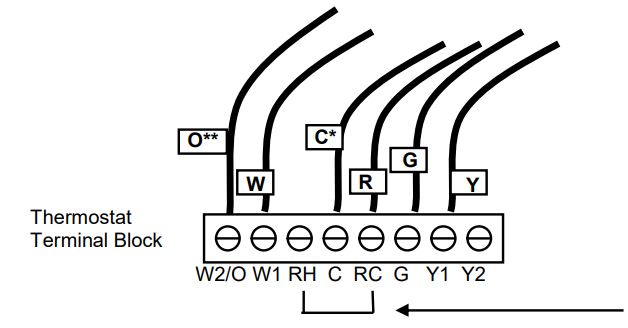
Connect the wires as marked from the HVAC system to the corresponding terminals on the thermostat back.*C wire (24VAC common) Heat Pump systems usually have the C wire connected to the thermostat.** O (Orange) or B (Brown) wire (changeover valve) connect to the W2/O terminal on the thermostat.
NOTE: Be sure to set the correct changeover operation (O = changeover with Cool, B = changeover with Heat) in the SETUP menu.Connect the R wire to either RC or RH terminal.Factory installed RC and RH jumper. Do not remove.
Finish Wiring
- If you have additional wires for 2 stage systems (W2, Y2), see the wiring diagrams on page 5 and 6.
- Check that the wires are screwed into the terminal blocks firmly.
- Gently pull on the wires to confirm the connection.
- Push all the excess wiring back into the wall.
Mount the thermostat
24VAC Powered Thermostat: If the thermostat is 24VAC powered (24VAC common “C” wire is connected).
- Install the thermostat on to the base.
- Turn on power to the HVAC system/thermostat.
Standard Gas/Electric HVAC System Wiring
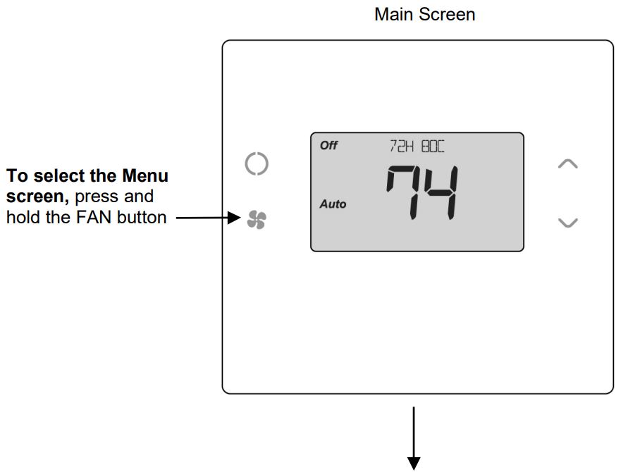
Thermostat Setup: Standard Gas/Electric HVAC SystemsFor Single Stage Heat/Cool Systems: Go to the Menu screen by pressing and holding the FAN button for 5 seconds Press the down arrow to select the SYSTEM menu and press Select. Set the following:
SYSTEM TYPE: Set to STANDARDFAN TYPE: Set to GAS for typical gas furnace (fan is controlled by the furnace) Set to ELECTRIC for electric heat (fan on with heat call)
For Two Stage Heat/Cool Systems: Go to ADVANCED SYSTEMS SETTINGS menu. From the Setup menu screen, press and hold the Fan and Down arrow buttons for 5 seconds. Use the Down arrow button to select the following:
2ND STAGE HEAT ENABLE: Enable second stage heating output If a single stage heating system, leave this set to N If a 2 stage heating system, set to Y to enable.
2ND STAGE COOL ENABLE: Enable second stage cooling output If a single stage cooling system, leave this set to N. If a two stage cooling system, set to Y to enable.
Default Thermostat Setup: Type: Standard HVAC Fan Type: Gas Heat 1 Stage heating 1 Stage coolingNo Setup change required for this configuration
Heat Pump HVAC System Wiring

Thermostat Setup: Heat Pump HVAC SystemsFor Single Stage Heat/Cool Systems:Go to the Menu screen by pressing and holding the FAN button for 5 seconds Press the down arrow to select the SYSTEM menu and press Select. Set the following:
Note! If you get heating when you expected cooling or vice versa, change the Change Over type to the opposite setting.
SYSTEM TYPE: Set to HEAT PUMPCHANGE OVER: For changeover with cooling systems (Orange wire): set to WITH COOL (most common and default setting)For changeover with heating systems (Brown wire): set to WITH HEAT You must configure the thermostat’s changeover valve setting to work correctly with your HVAC system.Check your system information to be sure and note the color of original thermostat wire and the terminal it was connected to. No matter what the old stat connection was (O or B), connect the wire to the thermostats W2/O terminal.
For Two Stage Heat/Cool Systems:Go to ADVANCED SYSTEMS SETTINGS menu. From the Setup menu screen, press and hold the Fan and Down arrow buttons for 5 seconds. Use the Down arrow button to select the following:AUXHEAT: If you have auxiliary heat strips, set this to Y to enable. (Default is Y)2ND STAGE HEAT ENABLE: Enable second stage heating outputs If a single stage heating system, leave this set to N If a 2 stage heating system, set to Y to enable.2ND STAGE COOL ENABLE: Enable second stage cooling outputs If a single stage cooling system, leave this set to N. If a two stage cooling system, set to Y to enable.
Thermostat Setup: Configure for HVAC System
The thermostat must be set up for the correct HVAC system type and configuration for proper operation.
Preset HVAC System settings The thermostat is preset for the following typical HVAC system configuration:
- HVAC system type: Standard gas/electric
- HVAC fan type: Gas heat
- HVAC heating stages: one
- HVAC cooling stages: one
If the thermostat is installed on this type HVAC system, the System setup does not need to be changed.Installation is complete
For thermostats installed on a Heat Pump HVAC system or any HVAC configuration other than the preset settings, the System settings need to be changed in the SYSTEM setup menu to match the HVAC system.
Changing the HVAC System SetupTo change the thermostats HVAC system settings, first select the Menu Screen and then select the SYSTEM menu. Follow instructions below to access the SYSTEM menu.
Note: The thermostat backlight turns off after a short time of no activity. The first press of any button will turn on the backlight but will not initiate any action other than turning on the backlight. Press the button again to initiate the action desired. If the backlight is already on, button presses work with the first press.
Go to Menu ScreenFrom the Thermostat Main Screen, Press and Hold the “FAN” button until the Menu screen is displayed.
 Thermostat Menu Screen
 Menu optionsWhen the thermostat Menu Screen is displayed, use the Up or Down arrow buttons to scroll through the following options:
- SETUP (user preference settings)
- SENSOR (displays “Paired” Sensor IDs)
- SYSTEM (HVAC system setup)
- BLE (Bluetooth advertising)
- INFO (firmware version)
Select SYSTEM setupTo change the HVAC system default settings, scroll down to the SYSTEM menu item and press “Select”.
SYSTEM setup menuThe SYSTEM menu is used to set up the thermostat for the correct HVAC system type.
- SYSTEM TYPE
- For Standard Gas/Electric systems, select “Standard”. This is the default setting.
- For Heat Pump systems, use the Up/Dn. arrows to change to “Heat Pump”
- Press Select to set.
- Press Done to exit
- FAN TYPE (For Standard HVAC systems only)
- Fan type depends on the heating system type.
- For Gas heat: select “GAS”. This is the default setting.
- For Electric heat: use the Up/Dn. arrows to change to “ELECTRIC”.
- Press Select to set
- Press Done to exit
- CHANGEOVER TYPE (For Heat Pump HVAC systems only)The changeover (or reversing) valve is used to change from heating to cooling operation. It is either a changeover with cooling type (Orange wire) or changeover with heating type (Brown wire). Most are changeover with cooling, which is the default setting.
- For Changeover with Cooling systems (Orange wire), select “WITH COOL”. This is the default setting.
- For Changeover with Heating systems (Brown wire), use the Up/Dn. arrows to change to “WITH HEAT”.
- Press Select to set
- Press Done to exit
Not sure which Changeover type?Check the existing thermostat connections to help determine this.
- If the original system had an orange wire connected to the “O” terminal, then this is a “changeover with cool” system.
- If there was a brown wire connected to the “B” terminal, then this is a “change over with heat” system.
- Set the Change Over setting accordingly. (Caution: These are typical wiring colors/connections and may differ)
- If heating comes on when cooling is expected or vice versa, change the “Change Over Type” to the opposite setting.
Bluetooth Advertising
To broadcast Bluetooth for pairing via Mobile App;
- Go to the Menu screen by pressing and holding the FAN button for 5 seconds
- Scroll down to SETUP menu items and press “Select”.
- Use the Up arrow to change to BLE
- Press Select Use Up arrow to select “Y”
- Press Done to exit
The thermostat screen will flash the BLE icon while broadcasting.
The Advanced System Settings Menu provides for addition system setup options. These settings can affect system operation and should only be changed by qualified HVAC installers.
To access the Advanced System Settings menu, first press and hold the Fan button to get to the MENU screen. Continue to hold down the Fan button and press and hold the Down Arrow button for 5 seconds. The first menu item in the Advance System Settings menu “Display Lock”, will be displayed. Use the Up/Down arrow buttons to scroll through the menu options to the desired setting. Press “Select” (Mode) button to change a setting. Once it begins to flash, use the Up/Down buttons to select the desired setting. Press the “Select” button to accept the new setting (flashing will stop).
Advanced Settings
Display LockY = Display LOCKEDN = Display UNLOCKEDRange: Y or NDefault: N
Allows the thermostat buttons to be locked. When the buttons are locked, none of the thermostat buttons will function as normal.
To unlock the thermostat, press and hold the FAN button for 5 seconds to access the Setup screen (it’s the only button that works in the lock mode). Access the AdvancedSettings Menu (as above) to turn the Display Lock off.
Test ModeRange Y or NDefault: N
Test modeshortens the system built-in delays (like MOT and MRT)Y= Test mode on. Reduces all delays to 10 sec for quicker system testingN= Test mode off. Normal system delays Test mode will time out after 30 min and return to normal operation.
Aux Heat Enable(Heat Pump Systems only) Range: Y or N Enables the Auxiliary Heat operation.Typically, the Aux Heat will be heat-strips in a Heat Pump system Aux heat control is wired to the W1 terminal.
2nd Stage Heat EnableDefault: YRange: Y or NEnables the 2nd Stage Heat operation
Minimum Run TimeRange: 1- 9 Minutes Default: 3Sets the Minimum Run Time (MRT) delay before a heating/cooling cycle can turn off. Sets heating/cooling cycle time. Prevents rapid on/off cycling.
Minimum Off TimeRange: 5-9 MinutesDefault: 5Sets the Minimum Off Time (MOT) delay before another heating/cooling cycle can begin. Provides compressor short cycle protection. “WAIT” is displayed on screen when active.
Heat Setpoint MaxRange: 30F to 109F (0C-43C) Default: 90F (32C)Sets the maximum heating setpoint value.Will not ramp or accept setpoints higher than this maximum.
Cool Setpoint MinRange: 33F to 112F (2C-45C) Default: 60F (15C)Sets the minimum cooling setpoint value.Will not ramp or accept setpoints lower than this minimum.
Heat Blower Off DelayRange: 0-90 seconds Default: 0 (off)Sets the system blower delay off time after a heat call ends (fan purge).
Cool Blower Off DelayRange: 0-90 seconds Default: 0 (off)Sets the system blower delay off time after a cool call ends (fan purge).
Heat – Cool DeltaRange: 3 – 15 degrees. Default: 3F (1C)Sets the minimum separation between heating and cooling setpoints.
SETPOINT PUSH
- Attempts to lower the cooling setpoint below the heating setpoint will PUSH the heating setpoint down to maintain the heat/cool delta separation.
- Attempts to set the heating setpoint above the cooling setpoint will PUSH the cooling setpoint up to maintain the setpoint heat/cool delta separation.
Heating Stage 1 On ThresholdRange: 1 to 6 degrees Default: 1Sets the delta from setpoint that stage 1 heating starts. Heat Blower Off Delay
Heating Stage 1 Off ThresholdRange: 0 to 5 degrees Default: 0Sets the delta from setpoint that stage 1 heating stops.Stage 1 turns off at setpoint + Delta Stage 1.
Heating Stage 2 On ThresholdRange: 2 to 7 degrees Default: 2Sets the delta from setpoint that stage 2 heating starts.
Heating Stage 2 Off ThresholdRange: 0 to 6 degrees Default: 0Sets the delta from setpoint that stage 2 heating stops.Stage 2 turns off at setpoint + Delta Stage 2.
Aux Heat On ThresholdRange: 3 to 8 degrees Default: 3Sets the delta from setpoint that stage 3 heating starts.
Aux Heat Off ThresholdRange: 0 to 7 degrees Default: 0Sets the delta from setpoint that stage 3 heating stops.Stage 3 turns off at setpoint + Delta Stage 3.
Cooling Stage 1 On ThresholdRange: 1 to 7 degrees Default: 1Sets the delta from setpoint that stage 1 cooling starts.
Cooling Stage 1 Off ThresholdRange: 0 to 6 degrees Default: 0Sets the delta from setpoint that stage 1 cooling stops.Stage 1 turns off at setpoint – Delta Stage 1
Cooling Stage 2 On ThresholdRange: 2 to 8 degrees Default: 2Sets the delta from setpoint that stage 2 cooling starts.
Cooling Stage 2 Off ThresholdRange: 0 to 7 degrees Default: 0Sets the delta from setpoint that stage 2 cooling stops.Stage 2 turns off at setpoint – Delta Stage 2.
Restore DefaultsRange: Yes, No Default: NoRestores all settings to factory defaults.Press Yes to restore defaultsPress No to exit and not restore defaults
Operation GuideModel TBH300 24VAC ZigBee/BLE/Clears Sky Thermostat
Main Thermostat Screen
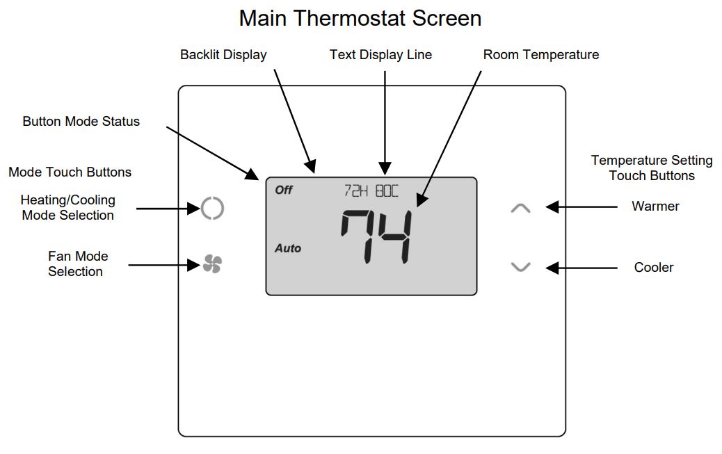
Backlight and Button OperationThe thermostat backlight is normally set to go out after 20 seconds of no button presses to conserve power. If the backlight is off, the first button press of any button will only turn on the backlight. Once the backlight is on, the buttons function normally.
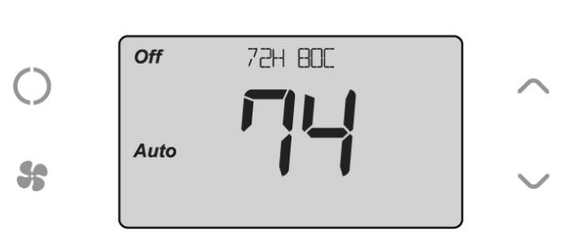
TBH300 Display
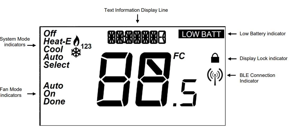
System Operation Modes![]() displayed = System is ON and heating. If flashing, minimum run time (MRT) is active
displayed = System is ON and heating. If flashing, minimum run time (MRT) is active![]() displayed = System is ON and cooling. If flashing, minimum run time (MRT) is active
displayed = System is ON and cooling. If flashing, minimum run time (MRT) is active
Stage Indicators“1” = Stage 1 heating or cooling is ON“2” = Stage 2 heating or cooling is ON“3” = Stage 3 heating (Aux Heat) is ON
For Heat Pump systems only:“Heat-E” = Emergency heat mode active
Setting the System Mode
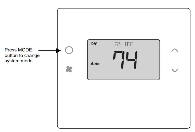
System Modes
- Off: System is off. No heating or cooling will come on. If system was on, it will turn off immediately.
- Heat: Only heating will occur.
- Cool: Only cooling will occur.
- Auto: Heating or cooling will come on according to the heating and cooling setpoints. The system will automatically switch between heating and cooling modes as needed to maintain the setpoints.
Special Heat Pump Mode: Emergency Heat
- Heat-E: An additional system mode, “Heat-E” for Emergency Heat will be displayed if the HVAC System Type is set to Heat Pump. If there is a compressor failure with the Heat Pump system, setting the mode to Emergency Heat will allow the supplemental Aux Heat to come on first whenever there is a call for heating. It also disables the compressor output to prevent further damage to the HVAC system.
Caution! Emergency Heat should only be used for emergencies until the HVAC system can be repaired. Running the system in Emergency Heat mode is commonly the most expensive mode since only the electric heat strips are being used instead of the more efficient heat pump compressor.
Setting the Heating or Cooling Temperature Setpoint
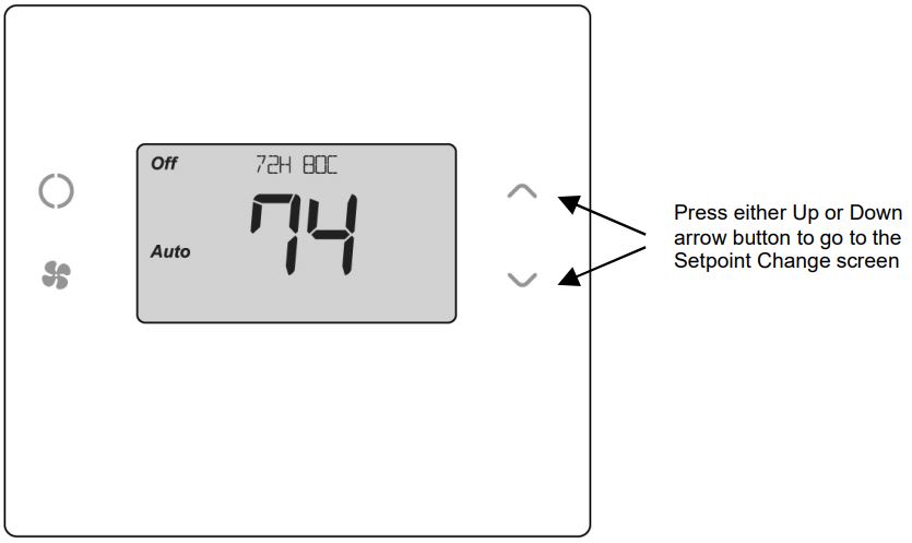
Setpoint Change screen
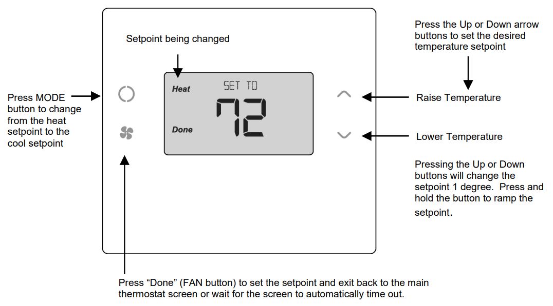
Setpoint ChangeTo change the setpoint, press the Up or Down arrow buttons. The screen will switch to the setpoint change screen (as above) and show the current setpoint of the current heating or cooling mode. Adjust setpoint temperature up or down with the arrow buttons.
Note! When in the Setpoint Change screen, pressing the MODE button will switch the setpoint being displayed between the Heat and Cool setpoints.
Setpoint Push: The cooling setpoint cannot be set below the heating setpoint. The thermostat will “push” the heating setpoint lower if the cooling setpoint is set below the current heating setpoint. A 3 degree separation is maintained between the heating andcooling setpoints. The same is true for raising the heating setpoint above the cooling setpoint. The thermostat will “push” the cooling setpoint up to maintain the 3 degree separation.
Setting the Fan Mode
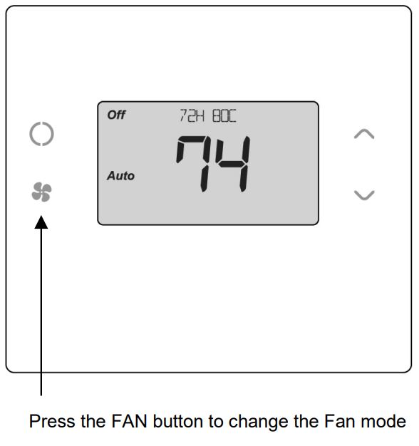
Fan Modes:
- Auto: Fan automatically operated by the HVAC system. (normal setting)
- On: Manual Fan mode. Fan stays on until mode is changed back to Auto, independent of the heating or cooling system operation.
Thermostat Menu Mode
The Thermostat has a menu of setup and information displays. To change to the Menu Mode, press and hold the FAN button for 5 seconds. The display will change to the Menu Mode and display the Setup screen. Use the Up/Down arrow buttons to scroll through other menu items.
Thermostat Main Screen

Menu Mode Screen

Menu Mode options
- SETUP User preference settings
- SYSTEM Thermostat HVAC system settings
- SENSOR
- INFO Displays thermostat version and setup info
SETUP MenuUser preference settings.
FAHRENHEIT or CELSIUS. Select the temperature display mode.
BACKLIGHT TIMEOUT. Sets the time from last button press that the backlight will turn off. Range:10-30 seconds. Note: long backlight timeouts will reduce battery life.
If the thermostat is powered from 24VAC, the backlight timeout can be set to “0” which will keep the backlight on continuously.
TEMPERATURE SENSOR CALIBRATION. Change the temperature calibration by +/- 7 degrees. Use the Up/Dn. arrow buttons to change to the desired temperature displayed.
HUMIDITY SENSOR CALIBRATION. Change the humidity calibration by +/- 7 percent. Use the Up/Dn. arrow buttons to change to the desired humidity displayed.
STATUS LINE Display. Select Setpoints or Humidity to be displayed on the upper status line.
SYSTEM Menu
SYSTEM TYPE. Select the system type, STANDARD or HEAT PUMP
FAN TYPE (Standard systems only). Select fan type: GAS (typical default setting) or ELECTRIC CHANGE OVER TYPE (Heat Pump systems only). Select the Changeover type:Changeover WITH COOL (typical default setting) Changeover WITH HEATSee Installation Guide for more information on System setup and the Advanced Systems Menu
INFO MenuThe INFO menu displays information about the thermostat. Use the Up/Dn buttons to scroll through the various items.Thermostat information displayed:
VERSION Thermostat firmware versionNODE ID Z-Wave Node IDHOME ID Z-Wave Home IDSYSTEM TYPE displays current System Type settings (Standard or Heat Pump)
If System Type = Standard FAN TYPE displays current Fan Type settingIf System Type = Heat Pump CHANGEOVER TYPE displays current Change Over valve (reversing valve) setting
AC Powered: AC POWER will be displayed if power by 24VAC
Thermostat OperationMinimum Run Time (MRT)The thermostat has a Minimum Run Time (MRT) delay after the start of any heating or cooling call. This minimum run time assures even heating and cooling cycles. The MRT will keep the system on, even if it reaches the setpoint room temperature, or you change the setpoint to a temperature that would satisfy the call, until the MRT expires. Changing the Mode to OFF will cancel the MRT and the system will turn off immediately. The MRT can be adjusted in the Advanced Settings menu of the thermostat.
Note: When MRT is active, the heating or cooling icon will be flashing.
Minimum Off Time (MOT)The thermostat has a Minimum Off Time (MOT) delay after any heating or cooling cycle ends. This delay prevents rapid heating/cooling cycles and also provides “short cycle protection” for the system compressor. This delay may be noticeable when you change a setpoint and it does not respond immediately due to the MOT delay timer preventing the system from restarting. The MOT delay time can be adjusted in the Advanced Settings menu of the thermostat but there is a minimum of a 5 minute delay to assure compressor protection.Note: When MOT is active, the thermostat Status Display shows “WAIT”.
FCC/ICINFORMATION TO USER
This device complies with Part 15 of the FCC Rules. Operation is subject to the following two conditions: (1) This device may not cause harmful interference, and (2) This device must accept any interference received, including interference that may cause undesired operation.
This equipment has been tested and found to comply with the limits for Class B Digital Device, pursuant to Part 15 of the FCC Rules. These limits are designed to provide reasonable protection against harmful interference in a residential installation. This equipment generates and can radiate radio frequency energy and, if not installed and used in accordance with the instructions, may cause harmful interference to radio communications. However, there is no guarantee that interference will not occur in a particular installation. If this equipment does cause harmful interference to radio or television reception, which can be determined by turning the equipment off and on, the user is encouraged to try to correct the interference by one or more of the following measures.
- Reorient or relocate the receiving antenna
- Increase the separation between the equipment and receiver
- Connect the equipment into an outlet on a circuit different from that to which the receiver is connected
- Consult the dealer or an experienced radio/TV technician for help
Any changes or modifications not expressly approved by the party responsible for compliance could void the user’s authority to operate the equipment.
 report this ad
This device complies with Industry Canada license-exempt RSS standard(s). Operation is subject to the following two conditions: (1) this device may not cause interference, and (2) this device must accept any interference, including interference that may cause undesired operation of the device.
[xyz-ips snippet=”download-snippet”]