Real Flame Ignite 50"/74"/100" Linear Electric Fireplace
[RF XLF50, RF XLF74, RF XLF100]User Manual

![]()
The product complies with the European Safety Standards EN60335-2-30 and the European Standard Electromagnetic Compatibility (EMC) EN55014, EN60555-2 and EN60555-3. These cover the essential requirements of EEC Directives 2006/95/EC and 2004/108/EC
Always use a quailed technician or service agency to repair this fireplace.
! NOTE: Procedures and techniques that are considered important enough to emphasize.
![]()
CAUTION: Procedures and techniques which, if not carefully followed, will result in damage to the equipment.
![]()
WARNING: Procedures and techniques which, if not carefully followed, will expose the user to the risk of ?re, serious injury, or death.
Welcome & Congratulations
Thank you and congratulations for purchasing an electric fireplace from Real Flame. Please take note of the location of the Model & Serial for this product it is important to be able to locate it in the event of requiring technical support.

Please carefully read and save these instructions.
![]()
CAUTION: Read all instructions and warnings carefully before starting installation. Failure to follow these instructions may result in a possible electric shock, ?re hazard and will void the warranty.
 IMPORTANT INSTRUCTIONS
Important Safety AdviceWhen using electrical appliances, basic precautions should be followed to reduce the risk of ?re, electric shock, andinjury to persons, including the following:If the appliance is damaged, check immediately with the supplier before installation and operation.Do not use this appliance in the immediate surroundings of a bath, shower or swimming pool.Do not use outdoors.This appliance must not be located immediately above or below a fixed socket outlet or connection box.WARNING : The appliance carries the Warning Symbol indicating that it must not be covered or has a Do not cover label. Do not cover or obstruct in any way the heat outlet grille located at the top of the appliance overheating will result if the appliance is accidentally covered. Do not place material or garments on the appliance, or obstruct the air circulation around the appliance, for instance by curtains or furniture, as this could cause overheating and a ?re risk.In the event of a fault unplug the heater. Unplug the appliance when not required for long periods. The supply cord must be placed on the right hand side of the heater away from the heat outlet underneath the appliance.Although this appliance complies with safety standards, we do not recommend its use on deep pile carpets or on long hair type of rugs.This appliance can be used by children aged from 8 years and above and persons with reduced physical, sensory or mental capabilities or lack of experience and knowledge if they have been given supervision or instruction concerning use of the appliance in a safe way and understand the hazards involved. Children shall not play with the appliance.Cleaning and user maintenance shall not be made by children without supervision.Children of less than 3 years should be kept away unless continuously supervised. Children aged from 3 years and less than 8 years shall only switch on/off the appliance provided that it has been placed or installed in its intended normal operating position and they have been given supervision or instruction concerning use of the appliance in a safe way and understanding the hazards involved.Children aged from 3 years and less than 8 years shall not plug in, regulate and clean the appliance or perform user maintenance.The appliance must be positioned so that the plug is accessible.If the supply cord is damaged it must be replaced by the manufacturer or service agent or similarly qualified person in order to avoid a hazard.
CAUTION: In order to avoid a hazard due to inadvertent resetting of the thermal cut-out, this appliance must not be supplied through an external switching device, such as a timer, or connected to a circuit that is regularly switched on and off by the utility.
CAUTION – Some parts of this product can become very hot and cause burns. Particular attention has to be given where children and vulnerable people are present.

Quick Reference Guide
- The electrical information regarding your electric ?replace can be found on the rating label located on the top of the unit.
- If you have any technical questions or concerns regarding the operation of your electric ?replace, or require service contact the relevant customer service as listed on your warranty card.
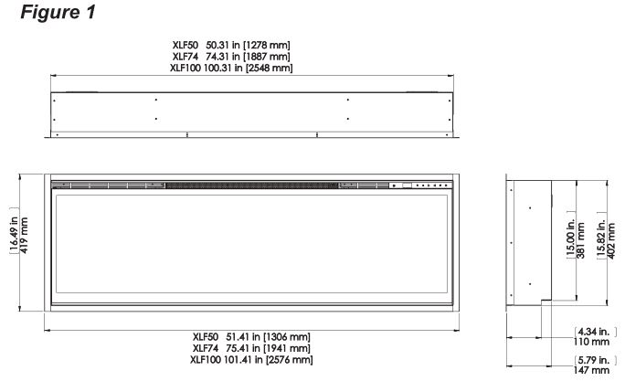
- For dimensions of your fireplace, refer to Figure 1.
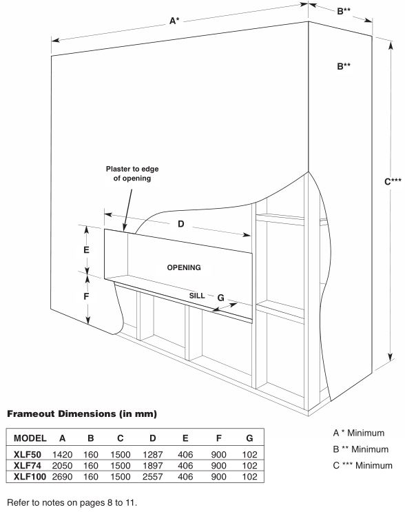
Framing Detail
Fireplace Installation
![]() CAUTION: Ensure installation does not allow fireplace to be in direct contact with building vapor barrier or insulation and meets all local building code.
CAUTION: Ensure installation does not allow fireplace to be in direct contact with building vapor barrier or insulation and meets all local building code.
NOTE: A 10 Amp, 230 – 240 Volt circuit is required. A dedicated circuit is preferred but not essential in all cases. A dedicated circuit will be required if, after installation, the circuit breaker trips or fuse blows on a regular basis when the heater is operating.
![]()
WARNING: Construction and wiring must comply with local building codes and other applicable regulations to reduce the risk of ?re, electric shock and injury to persons.
![]() WARNING: To reduce the risk of fire, electric shock or injury to persons, always use a licensed electrician.
WARNING: To reduce the risk of fire, electric shock or injury to persons, always use a licensed electrician.
![]() WARNING: To reduce the risk of fire, do not store or use gasoline or other flammable vapors or liquids in the vicinity of the heater.
WARNING: To reduce the risk of fire, do not store or use gasoline or other flammable vapors or liquids in the vicinity of the heater.
- Select a location that is not susceptible to moisture and is away from drapes, furniture and high traffic.
- Unpack the ?replace and hardware from the box.! NOTE: Leave the front glass and partially reflective glass, safely, in the box until the time you are ready to install it.
- Store the ?replace in a safe, dry and dust free location until you are ready to install the fireplace.
Installation
![]()
CAUTION: Two people will be required for various steps of this procedure.
This design of this unit allows three options for installation: partial recess, flush mounted or sub-surface mounted.
![]()
CAUTION: Sub-surface mounting should be limited to ½ in. (12 mm) to ensure adequate air flow of heated air out of the firebox area.
- Prepare a wall with a framed opening of 16 in. (40.6 cm) high,• XLF50 – 50 ⅝ in. (128.7 cm)• XLF74 – 74 ⅝ in. (189.7 cm)• XLF100 – 100 ⅝ in. (255.7 cm) wide, with a bottom sill that is a minimum of 4 in. (10.2 cm) deep. The sill can be constructed to support the front of the unit to allow the power supply wires to easily be run behind or flush with the back of the unit and a pass thru hole drilled for electrical wire routing.! NOTE: It is recommended that the bottom of the unit be mounted between 30 in. (76.2 cm) and 40 in. (102 cm) from the ground to maintain an optimized viewing angle of the flame.WARNING: Do not attempt to wire your own new circuits. To reduce the risk of ?re, electric shock or injury to persons, always use a licensed electrician.WARNING: Ensure that the circuit on which the ?replace is to be installed has the power cut off at the service panel until installation is complete.
- The unit is provided with an installed ¾ in. (2.0 cm) trim. Depending on the installation, this trim can be removed by removing the securing screws and the 4 trim pieces.
- Lift ?replace, from the bottom and the handles located on the back, and insert into opening to the desired depth.
- Using a bubble level (supplied) ensure that the ?replace is level within the framing. Adjust as required.
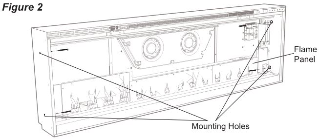
- Drive four supplied mounting screws through the four mounting holes located on the inside surface of the ?replace chassis, into wall studs (Figure 2).
For Bathroom Use
If this unit is installed in a bathroom it must be protected by a GFI receptacle or circuit. If receptacle is used it must be readily accessible.
To prevent electrical shock this unit is an electrical appliance that is NOT watertight and must be installed as to prevent water from entering unit. This must be installed away from showers, tubs, etc. Never locate ?replace where it may fall into a bathtub or other water container.
Final Assembly
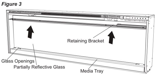
- Locate and remove the 12 screws securing the partially reflective glass bracket to the unit, along the top of the opening, and set bracket and screws aside.
- Remove the provided suction cup from the inside cavity of the unit (only for XLF74 and XLF100 units).
- Before installation ensure that the front glass and the partially reflective glass are clean. Particles can be removed by dusting lightly with a clean dry cloth. To remove fingerprints or other marks, the glass can be cleaned with a damp cloth. Ensure that the glass has completely dried before installation.
- Carefully secure the suction cup to the partially reflective glass, reflective side out, and place into the openings on either side of the unit.
- Tip the glass into the unit and using the removed screws secure the glass into the unit with the provided bracket (Figure 3). Remove the suction cup.
- Evenly space the large media in the media tray along the back of the media tray (for optimum media effect), then carefully pour and evenly distribute the smaller media into the Media Tray.
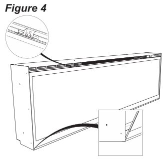
- Carefully place the front glass into the lip located at the bottom of the opening of the firebox.
- Tip the front glass into the unit and secure using the provided screws and Allen key. (Figure 4).! NOTE: Ensure that the suction cup and Allen key are kept for any future maintenance or service.
Operation
General Operation
![]()
WARNING: This electric firebox must be properly installed before it is used.
This firebox operates with Comfort $aver™ technology, which automatically adjusts the fan speed and heater wattage to safely and precisely match the requirements of the room based on the thermostat setting. The heater operates such that once the room reaches the set point, the fan and heater will continuously run at a low level, to maintain the desired room temperature. If the temperature in the room rises significantly, i.e. sun coming through a window or a central furnace turns on, the heater will turn off and periodically turn back on to circulate the air around the unit, until the room temperature drops and requires the heater to be constantly on again.
! NOTE: The unit is designed so that the fan will run continuously while the heater is on.
! NOTE: The element retains heat after shutdown, there is a built in cool down period of 2 minute before the fan shuts off completely, when the heat function is turned Off.
Remote Operation
The fireplace is supplied with an IR multi-function remote control.
! NOTE: To operate correctly, the remote control must be pointed towards the front of the unit.
Controls
The unit can be controlled by either the manual controls which are located on the upper right of the fireplace or the remote (Figure 5 & 6).
A. Standby
Turns the unit On and Off.→ Activated by pressing the Standby button on the remote or the unit.
- The unit will turn On with the same functions that it was set to when it was turned Off and the intake temperature will be indicated on the Display.
! NOTE: When any button is pressed on the unit the intake temperature will be displayed on the Display for 7 seconds.
B. Flame Effects
Turns the Flame Effect On and Off.→ Activated by pressing the ![]() button on the remote.
button on the remote.
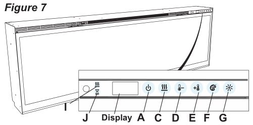

C. Heat ON/OFFTurns the heater On and Off.→ Activated by pressing the heat button on the remote or the unit.
- Indicated by the heat icon and the setpoint temperature will flash on the display, then the intake temperature will be displayed before turning off.
! NOTE: After the heater is switched off, there is a 2 minute fan delay, where the fan will continue running before turning off.
! NOTE: The unit can be operated in Heat Only Mode. When the unit is only running with the heater, the heat icon will continuously be displayed on the Display.
! NOTE: The heater may emit a slight, harmless odor when first used. This odor is a normal condition caused by initial heating of internal heater parts and will not occur again.
D. Temperature Down
Decreases the temperature setting.→ Adjusted by repeatedly pressing the corresponding button on the remote.*
- Indicated by setpoint temperature on the Display decreasing and the speed of the fan decreasing to reduce the amount of heat being projected into the room.**
E. Temperature UpIncreases the temperature setting.
→ Adjusted by repeatedly pressing the corresponding button on the remote.*
- Indicated by the setpoint on the Display increasing and the speed of the fan increasing to increase the amount of heat being projected into the room.
* The first time the button is pressed the current temperature set point will be displayed for 2 seconds.** The temperature can be adjusted from 5 °C to 37 °C (41 °F to 99 °F).
! NOTE: Holding the Temperature Up and the Temperature Down buttons down for two seconds, on the unit, will change the temperature scale from °C to °F, or vice versa.
F. Eco OperationRuns the heater in a reduced wattage range when activated.→ Adjusted by pressing the corresponding button on the remote when the heater is on.
- Indicated by the Display and a reduced fan speed.
G. Heat Boost
Turns the Heater Boost On and Off. Runs the unit at the full rated wattage.
→ Activated and adjusted by repeatedly pressing the corresponding button on the remote.
- Indicated by the heater running at full heat, for a user set amount of time, to quickly heat up a cold room/space. The Heat Boost can be set for a maximum of 20 minutes, in 5 minute increments.
Disable Heat
If desired, depending on the season, the heater on the unit can be disabled. The function of the remaining controls will continue to function as outlined in this manual.
Pressing the heat and temperature down buttons on the unit at the same time and holding for 2 seconds will disable and enable the heater.
! NOTE: When the heater has been disabled and any of the heat related functions are used, the Display will indicate “—“.
F. Color Themes
Different presets of lighting color combinations are available in the unit.→ Changed by repeatedly pressing the corresponding button on the remote or the unit.
- Cycles through the different preset light settings of the unit, this includes different combinations of colors of the flame base and media lighting.
! NOTE: Two of the themes in the cycle are a prism where the unit cycles through a variety of colors. Pressing the stops thecycling and holds the unit on the preferred color, indicated by a solid circle. When the unit is on prism, and is cycling through the colors, a rotating circle will be displayed.
G. BrightnessChanges the Brightness of the lights in the unit.
→ Adjusted by repeatedly pressing the corresponding button on the remote or the unit.
- Indicated by the second digit on the Display changing to show: “H” (high), and “L” (low).
H. Sleep TimerThe Sleep Timer can be set to automatically shut off the ?replace after a preset time (from 30 minutes to 8 hours).→ To set the timer press the timer button on the remote, repeatedly, until the desired time is displayed.
- The Display will display the different times as it is adjusted. Once the timer has begun, pressing the button will display the time remaining before the unit turns Off.
! NOTE: The Sleep Timer can be cancelled at any time by pressing the button repeatedly until the sleep timer displays nothing.
Resetting the Temperature Cutoff Switch
Should the heater overheat, an automatic cut out will turn the whole unit off and it will not come back on without being reset. If the button on the unit is pressed, Er2 will be displayed on the unit. It can be reset by turning the unit off at the main disconnect panel and waiting 5 minutes before turning the unit back on.
![]()
CAUTION: If you need to continuously reset the heater, turn the unit off at the main disconnect panel and call technical support.
Remote Control Battery Replacement
To replace the Battery:
- Slide battery cover open on the remote control.
- Correctly install one 3 Volt (CR2032 [longer life] or CR2025) Battery in the battery holder.
- Close the battery cover. Battery must be recycled or disposed of properly. Check with your Local Authority or Retailer for recycling advice in your area
Maintenance
![]()
WARNING: Disconnect power and allow heater to cool before attempting any maintenance or cleaning to reduce the risk of fire, electric shock or damage to persons.
! NOTE: The ?replace should not be operated with an accumulation of dust or dirt on or in the unit, as this can cause a build up of heat and eventual damage. For this reason the heater must be inspected regularly, depending upon conditions and at a minimum yearly intervals.
Partially Reflective Glass CleaningThe partially Reflective glass is cleaned in the factory during the assembly operation. During shipment, installation, handling, etc., the partially Reflective glass may collect dust particles; these can be removed by dusting lightly with a clean dry cloth.To remove fingerprints or other marks, the partially Reflective glass can be cleaned with a damp cloth. The partially Reflective glass should be completely dried with a lint free cloth to prevent water spots. To prevent scratching, do not use abrasive cleaners.
Fireplace Surface CleaningUse only a damp cloth to clean painted surfaces of the fireplace. Do not use abrasive cleaners.
![]() RecyclingFor electrical products sold within the European Community. At the end of the electrical products useful life it should not be disposed of with household waste. Please recycle where facilities exist. Check with your Local Authority or retailer for recycling advice in your country.
RecyclingFor electrical products sold within the European Community. At the end of the electrical products useful life it should not be disposed of with household waste. Please recycle where facilities exist. Check with your Local Authority or retailer for recycling advice in your country.
After Sales ServiceYour product is guaranteed for one year from the date of purchase. Within this period, we undertake to repair or exchange this product free of charge (excluding lamps & subject to availability) provided it has been installed and operated in accordance with these instructions. Your rights under this guarantee are additional to your statutory rights, which in turn are not affected by this guarantee.
Should you require after sales service you should contact our customer services the contact number is located on your warranty card. It would assist us if you can quote the model number, series, date of purchase, and nature of the fault at the time of your call. The customer services help desk will also be able to advise you should you need to purchase any spares. Please do not return a faulty product to us in the first instance as this may result in loss or damage and delay in providing you with a satisfactory service. Please retain your receipt as proof of purchase.
![]()
GLEN DIMPLEX AUSTRALIA PTY LTDABN 69 118 275 460Head Office/Factory/Showroom1340 Ferntree Gully Rd.Scoresby Vic 3179Ph: (03) 8706 2000 Fax: (03) 8706 2001E-mail: [email protected]Richmond – VIC Showroom300 Swan St.Richmond Vic 3121Ph: (03) 9428 4443 Fax: (03) 9428 4445Dandenong – VIC Showroom3/328 South Gippsland Highway,Dandenong South Vic 3164Ph: (03) 9702 7853E-mail: [email protected]Geelong – VIC Showroom1/2A Gordon Avenue.Geelong West Vic 3218Ph/Fax: 5229 0844E-mail: [email protected]Sydney – NSW Showroom546 Pacific Highway.Chatswood NSW 2067Ph: (02) 8905 0189 Fax: (02) 8905 0192E-mail: [email protected]Miranda – NSW Showroom36 Kareena RdMiranda NSW 2228Ph: (02) 8513 6202 Fax: (02) 9520 1974E-mail: [email protected]Adelaide – SA Showroom173 -175 Magill Rd.Norwood SA 5067Ph: (08) 8132 0371 Fax: (08) 8132 1687E-mail: [email protected]Milton – QLD Showroom46 Douglas St,Milton QLD 4064Ph: (07) 3368 2011Perth – WA Showroom47-53 McDonald St East,Osborne Park WA 6017Ph: (08) 9444 9900 Fax: (08) 9444 9800Fyshwick – ACT Showroom88 Wollongong St,Fyshwick ACT 2609Ph: (02) 6280 5522Ulverstone – TAS Showroom31A Victoria St,Ulverstone TAS 7315Ph: (03) 6425 4440
Real Flame Ignite 50″/74″/100″ Linear Electric Fireplace [RF XLF50, RF XLF74, RF XLF100]User Manual – Real Flame Ignite 50″/74″/100″ Linear Electric Fireplace [RF XLF50, RF XLF74, RF XLF100] User Manual –
[xyz-ips snippet=”download-snippet”]