
![]() WARNING!
WARNING!
AGE WARNINGI
- This radio-controlled (RC) vehicle is not a toy! You must be 14 years of age or older to operate this vehicle. Adult supervision is required.
RISK OF RUNAWAY VEHICLE OR INJURY,
- Never turn on the vehicle or plug in the battery pack without first having the controller turned on.
RISK OF FIRE
RISK OF EXPLOSION!
- There is a risk of fire and explosion when dealing with batteries. Rechargeable batteries may become hot and catch fire if left unattended or charged too quickly.
- Use extra caution when charging LiPO batteries. Use only LP° specific chargers. Use a UPO safe charging pouch when charging LiP0s. Charge away from flammable – materials.
- Never charge at a rate higher than 1 C. (2000Mah pack- lamps charge rate). Overcharging can lead to fire and explosion. Always store battery packs in a cool dry place.
- Never leave the battery plugged into the ESC when the vehicle is not in use.
- Never connect two batteries to one another.
RISK OF BURNS,
- The batteries, electronic speed controller (ESC), electric motor, and other areas of the vehicle can get hot Burns can occur if touched after the vehicle Allow adequate time to cool before handling.
RISK OF ELECTRICAL. SHOCK!
- Use caution when charging batteries. Do not touch positive and negative leads together.
- Do not lay the battery on metal. Use only chargers specified for the battery type being charged.
- Keep batteries and chargers away from water.
RISK OF INJURY!
- Hobby-grade RC vehicles can cause serious injury or death if not operated correctly.
- Never use vehicles in crowds. Never chase people or animals. Only drive in safe open areas.
- Keep body parts away from moving parts.
RISK OF DAMAGE!
- Never operate RC vehicles on public roads. Damage to vehicles and property can occur. Only operate on open private property.
- Never charge the battery pack while it is still plugged into the RC vehicle. Always unplug the battery pack from the electronic speed controller (ESC) and remove the battery from the RC vehicle before charging. Failure to do so will result in damage to the vehicle’s electronics and void the electronics warranty.
RISK OF RUNAWAY VEHICLE OR INJURY AND DAMAGE
- Do not mix old and new batteries. Do not mix alkaline, lithium, standard (carbon-zinc), or rechargeable (nickel-cadmium) batteries. Do not change or charge batteries in a hazardous location. Only use new AA batteries in your radio transmitter. Replace transmitter batteries often to ensure full control of the vehicle.
- Perform a radio range check BEFORE running your RC vehicle to avoid a runaway vehicle.
FCC COMPLIANCE STATEMENT!
• The radio included with your vehicle complies with part 15 of the FCC Rules.Operation is subject to the following two conditions:
- This device may not cause harmful interference, and
- This device must accept any interference received, including interference that may cause undesired operations.
Note: This equipment has been tested and found to comply with the limits for a Class B digital device, pursuant to Part 15 of the FCC Rules. These limits are designed to provide reasonable protection against harmful interference in a residential installation. This equipment generates, uses, and can radiate radio frequency energy and, if not installed and used in accordance with the instructions, may cause harmful interference to radio communications. However, there is no guarantee that interference will not occur in a particular installation. If this equipment does cause harmful interference to radio or television reception, which can be determined by turning the equipment off and on, the user is encouraged to try to correct the interference by one of the following measures:
Reorient or relocate the receiving antenna. Increase the separation between the equipment and receiver. Connect the equipment into an outlet on a circuit different from that to which the receiver is connected. Consult the dealer or an experienced radio/TV technician for help.
- WARNING: Any changes or modifications not expressly approved by the party responsible for compliance could void the user’s authority to operate this equipment
- WARNING: While operating the Radio, a separation distance of at least 20 centimeters must be maintained between the radiating antenna and the body of the user or nearby persons in order to meet the FCC RF exposure guidelines.
![]() Perform a radio range check:
Perform a radio range check:
- Install new AA batteries into the bottom of the transmitter.
- Turn on the transmitter.
- Turn on the ESC power switch, which is found in the vehicle.
- Check that the controls are working properly.
- Keep fingers away from potentially moving parts and hold the vehicle off the ground.Note: Always turn on the transmitter first to prevent runaways.
- Check that the controls are working properly. The steering wheel should operate steering and the trigger should operate the motor. Pulling the trigger should make the vehicle go forward, pushing the trigger should apply the brake and reverse. You may need to adjust the throttle trim found on the transmitter to keep the wheels from spinning while the trigger is in the neutral position.
- Have a friend hold the vehicle and walk 50 yards away. You and your friend should decide on a routine beforehand since it will be difficult to communicate with each other while testing.An example would be:
- Turn the steering wheel left and count to ten
- Tum the steering wheel right and count to ten
- Pull the trigger and count to ten
- Push the brakes and count to ten.
- You will want to repeat these steps moving further out as you progress until you are beyond the maximum distance you plan to run the vehicle.
- If the radio is performed without any glitches or twitching at maximum distance, you are ready.
![]() Water Warning:
Water Warning:
- After the vehicle gets wet, please unplug the ESC from the battery to avoid putting users in danger. Also, rustproofing the bearings and metal parts is highly recommended.

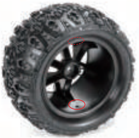
- If you feel driving in water is necessary, please seal all holes in the tires and rims before performing this action to prevent the tire foam from absorbing water inside the tires.
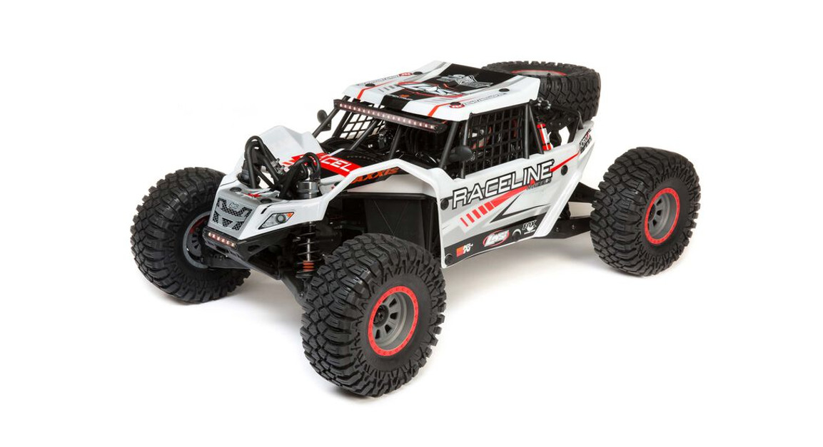
 Thank you for choosing the Redcat RC-MT1 OE monster truck. The RC-MT1 OE is designed to be fun to drive and uses top-quality parts for performance and durability. Before you start using your new RC kit, we suggest you read through the instruction manual first. Be sure to check all tips before you start. We hope you enjoy your new Redcat RC.

| Features: | Specifications: |
|
|
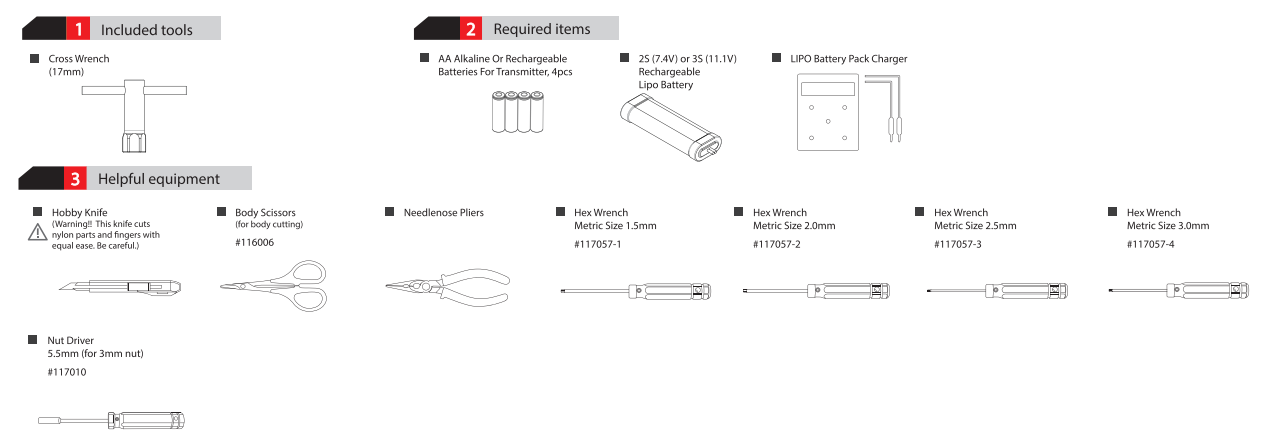
![]() Thank you for purchasing the RC-MT1 OE. To drive the vehicle, you will need to acquire the following items.
Thank you for purchasing the RC-MT1 OE. To drive the vehicle, you will need to acquire the following items.
Instruction & Setup Manual
- Transmitter Function
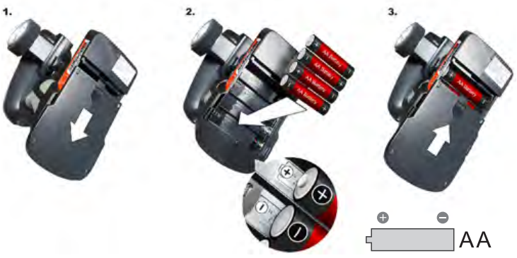
- Operating Procedure• Install 4pcs AA batteries into the transmitter.• Do not mix old and new batteries. Do not mix alkaline batteries, standard (carbon-zinc) or rechargeable (nickel-cadmium) batteries.• Turn the steering wheel right to steer the front tires right.• Turn the steering wheel left to steer the front tires left.• Pull the throttle trigger to move the vehicle forward.• Push the throttle trigger forward to brake and reverse the vehicle.
 • Turn the steering wheel right to steer the front tires right.• Turn the steering wheel left to steer the front tires left.
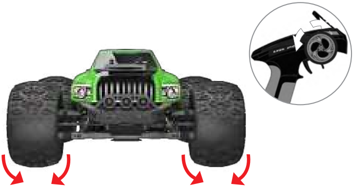 • Pull the throttle trigger to move the vehicle forward.• Push the throttle trigger forward to brake and reverse the vehicle.
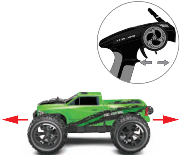
Additional Controls & Binding
Radio:
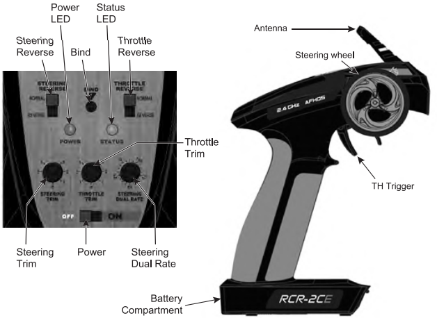
Steering Reverse Switch: Top left switch. Used to change steering orientation. If the car turns right when you steer left, flip this switch.Throttle Reverse Switch. Top right switch. Used to change throttle trigger orientation. If the car goes in reverse while you pull the throttle trigger, flip this switch. Power LED: Left LED light. Lights up when the transmitter is turned on.Status LED: Right LED light. Lights up green when transmitter batteries are full. Flashes when transmitter batteries are low and need replacing. Bind Button: Used to bind the transmitter to the receiver. See binding instructions.Steering Trim: Left knob. Used to set the steering neutral point. If the vehicle veers in one direction while the steering wheel is centered, turn this knob in the opposite direction until the car drives straight.Throttle Trim: Middle knob. Used to set the throttle neutral point. If the vehicle moves forward or reverses while the throttle trigger is centered, turn this knob until the vehicle remains still. For maximum setting, turn slowly until the vehicle creeps forward, then turn the knob in the opposite direction until the car stops. Steering Dual Rate: Right knob. Used to limit the amount of steering. 0= little/no steering & 100= maximum steering. Set the knob to the amount of steering you feel comfortable with. If the vehicle has a tendency to spin out, lower the steering rate.On/Off Switch: Bottom switch. Turns transmitter On and Off.
Receiver:
BINDNCC: Used when binding to the transmitter.Ch3: Used for 3rd channel when needed.Ch2: Used for electronic speed controller (ESC).Ch1: Used for steering servo.Failsafe Button: Used to set failsafe.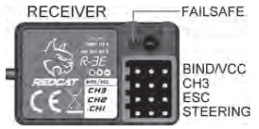
Binding Process:
- Insert the BIND PLUG into the receiver BIND port.
- Make sure your ESC is plugged into CH2, and insert the bind plug into BINDNCC. Now, power the vehicle on, and the receiver light should begin to blink
- Press the BIND button in the center of the transmitter’s Control Panel and turn on the radio.
- Release the bind button when you see the green light on the radio flashing. At this point, your receiver’s LED light should pause for approximately 1 second and then blink slowly. Turn off the power to your vehicle, as well as the radio.
- Remove the BIND PLUG from the receiver. Make sure the servos and ESC are attached as described above.
- First, turn your radio on, then your vehicle as normal. Your radio and receiver should be bound together and communicating with each other.
ESC Features
- ESC is compatible with sensorless brushless motors and sensored brushless motors (only in sensorless mode).
- Fully waterproof design for all weather conditions. After running in water, clean and then dry the ESC to avoid the oxidation of copper connectors)
- Super internal switch-mode BEC with switchable voltage of 6V/7.4V and a cont ./peak current of 3A/6A for use with high torque servos and high voltage servos.
- A highly reliable electronic switch avoids troubles that may happen to traditional mechanical switches.
- Proportional brake with 9 levels of maximum brake force and drag brake force.
- 5 levels of acceleration/punch from soft to aggressive for different terrain, tires, and tracks.
- Multiple protections: motor lock-up protection, low-voltage cutoff protection, thermal protection, overload protection, fail-safe (throttle signal loss protection), and capacitor damage protection.
- Single-button ESC programming and factory reset, or advanced programming via portable LED program card (sold separately) or multifunction LCD program box (sold separately).
ESC Specifications
| Model | EZRIN-MAX10 |
| Continuous/Burst Current | 80A / 520A |
| Motor Supported | Sponsored / Sensorless Brushless Motor (only in sensorless mode) |
| Programming Port | Fan / Programming Port |
| Motor Limit | 2S LIPO/6 Cell NiMH: KV<5000/ 3S LIPO/9 Cell NiMH: KV<3000 (3656 size motor) |
| Fan (included) | Powered by a stable BEC voltage of 6V / 7.4V |
| Battery | 2-3S Lipo / 6-9 Cell NiMH |
| BEC Output Notes1 | 6V 17.4V Switchable, 3A Continuous Current (Switch Mode) |
| Dimensions | 49mm(L)*39.5mm(W)*34.7mm(H) |
| Weight | 105g |
NOTE 1: The cooling fans Powered by the stable BEC voltage of 6V/7.4V and is always working.
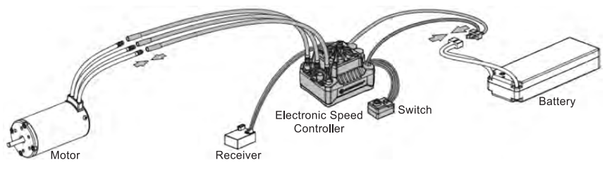
ESC Connections
- Motor WiringThere is no polarity on the A/B/C ESC/MOTOR wires. If the motor runs in reverse, just swap two of the wires.
- Receiver WiringPlug the receiver cable (a small black plug with three small wires coming out of it) into the throttle (2CH) on the receiver. Do not connect an additional receiver battery into the receiver, this may damage the ESC.
- Battery WiringPlug the approved (see above) battery pack into the ESC battery plug. Be sure the polarity is correct! The red (+) of ESC to the red (+) of the battery, and the black (-) of the ESC to the black (-) wire of the battery. If the polarity is reversed, the ESC will be damaged. This will not be covered under warranty!
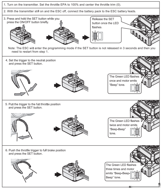
ESC Calibration
To ensure transmitter throttle input corresponds with the ESC output, you should calibrate the ESC. Do this whenever you change transmitters, and before you set the TRIM, D/R, EPA, and other throttle channel parameters on your transmitter. Follow these steps below.
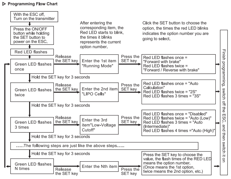
ESC Programming
(Shaded boxes indicate factory default settings)
| Programmable Items | Parameter Values | ||||||||
| Basic Setting Option # | # 1 | # 2 | # 3 | # 4 | #5 | #6 | #7 | #8 | #9 |
| 1. Running Mode | Fwd/Br | Fwd/Rev/Br | |||||||
| 2. LiPo Cells | u o io | 2S | 3S | ||||||
| 3. Low Voltage Cutoff | Disabled | Auto (Low) | interstate | Auto (High) | |||||
| 4. ESC Thermal Protection | 105t/221 ^F | 125,c/257°F | |||||||
| 5. Motor Thermal Protection | Disabled | ||||||||
| 6. Motor Rotation | CCW | CW | |||||||
| 7. BEC Voltage | 6.0V | 7.4V | |||||||
| 8. Brake Force | 12.5% | 25% | 37.5% | 50.0% | 62.5% | 75.0% | 87.5% | 100.0% | Disabled |
| 9. Reverse Force | 25% | 50% | |||||||
| 10. Start Mode (Punch) | Level 1 | Level 2 | Level 3 | Level 4 | Level 5 | ||||
| Advanced Setting | |||||||||
| 11. Drag Brake 0% 2% | 4% | 6% | I 8% | 10% | 12% | 14% | 16% |
1. Running Mode
- Option 1: Forward with BrakeThe vehicle can go forward and brake but cannot reverse in this mode. This mode is used for racing.
- Option 2: Forward / Reverse with BrakeThe vehicle can go forward, brake, and reverse. This mode uses the “DOUBLE-CLICK” braking/reverse method. The vehicle only brakes (won’t reverse) the 1st time the throttle trigger is pushed forward. When the motor stops and you quickly release and re-push the trigger forward a second time, the vehicle will go into reverse. If the motor does not stop, the vehicle will remain in braking mode. The reverse is only activated if the motor has completely stopped.
- 2. LiPo Cells“Auto Calculation” is the default setting. If you regularly use the same size LIPO pack, we recommend setting this option manually to avoid incorrect auto calculations. The ESC may mistake a partially charged 3S LIPO for a fully charged 2S LIPO allowing the 3S LIPO to drop below its safe voltage range, causing damage to the battery. To avoid this, only turn on the ESC with a fully charged battery pack installed, or set this option manually according to the LIPO battery cell count being used.
- 3. Low-Voltage CutoffSets the voltage range the ESC lowers or removes power to the motor in order to keep the battery at a safe minimum voltage (for LIPO batteries). The ESC will monitor the battery voltage (according to the cell count set above) and will reduce power to 50% allowing you to drive the vehicle back to yourself. If you are still driving 10 seconds beyond the power drop, all power to the motor will be cut. This is to keep the LIPO batteries from dropping below their safe voltage threshold. The RED LED will flash a short, single flash that repeats (• • •) to indicate the low-voltage cutoff protection is activated.
- Option 1: DisabledThe ESC will not monitor voltage. This setting is for NiMH battery packs only. Do not use this setting while using LIPO batteries or they may be irreversibly damaged.
- Option 2: Auto (Low)For batteries with a poor discharge capability. Not recommended.
- Option 3: Auto (Intermediate)For batteries with a normal discharge capability. Recommended.
- Option 4: Auto (High)For batteries with a very high discharge capability.Warning: ALWAYS use Low-Voltage Cutoff when using LIPO batteries!
ESC Programming (cont.)
- 4. ESC Thermal (Shutdown) Protection/Overheat ProtectionThe ESC will automatically cut off the output and the GREEN LED will flash a short, single flash that repeats (• • -) when the temperature gets up to the value you preset and activates the ESC thermal protection. The output won’t resume until the temperature gets down. Setting #1 is recommended.
- 5. Motor Thermal (Shutdown) Protection/Overheat ProtectionThis item has been permanently set to “Disabled” by the manufacturer.
- 6. Motor RotationChanges the rotation of the motor while it’s the shaft is facing you. Counterclockwise or clockwise.
- 7. BEC Voltage :Changes the voltage supplied to the servos. Use 6.0V for regular servos and 7.4V for high voltage servos.
- 8. Brake ForceSets the overall braking power when the brake trigger is pushed all the way forward (full brake). A high setting will shorten the braking time but it may damage your pinion and spur.
- 9. Reverse ForceThe amount of power the vehicle will have while the full reverse is engaged. Start with a low setting.
- 10. Start Mode (Punch)The amount of initial power while initially pulling the throttle trigger. You can choose a punch level from 1 (very soft) to 5 (very aggressive). This feature is very useful for preventing tire spin during takeoff. This function may be limited to battery capabilities. If the vehicle stutters during takeoff, you will need to lower the punch setting or use a battery with higher discharge capabilities.
- 11. Drag BrakeDrag brake is the amount of brake automatically applied while the throttle is in the neutral position. This is to simulate the natural drag of a brushed motor while coasting.
ESC Troubleshooting
| Trouble | Possible Reason | Solution |
| After power on, the motor and cooling fan don’t work. | No power was supplied to the ESC. | Check if all ESC & battery connectors have been well soldered or firmly connected. |
| The ESC switch is damaged. | Replace the broken switch. | |
| After power on, the motor doesn’t work, but emits “beep beep-, beep- beep-‘ alert tone. (Every “beep- beep– has a time interval of 1 second)After the ESC was powered on and finished LiPo cell detection (the GREEN LED flashed N times). and then the RED LED lashed rapidly.The motor runs in theopposite direction when it is acceleratedThe motor suddenly stops running while in a working state | Input voltage is abnormal, too high or too low.The ESC didn’t detect any throttle signal. | Check the voltage of the battery pack.Be sure the throttle wire is properly plugged into the receiver and in the correct channel. Ensure the transmitter is turned on. |
| The neutral throttle value stored on your ESC is different from the value stored on the transmitter.The (ESC-to-motor) wiring order was incorrect. | Re-calibrate the throttle range after you release the throttle trigger to the neutral position.Swap any two-wire connections between the ESC and the motor.Check the transmitter and the receiver. Check the signal wire from the throttle channel of your receiver.Red LED flashing means Low Voltage. Green LED flashing means Over-heat. | |
| The transmitter throttle channel is reversed. The throttle signal is lost.The ESC has entered into Low Voltagep on Mode or Over-heat ProtectionMrodeotecti | ||
| The motor stutters but won’t run properly. | A soldering Joint between the motor and the ESC may be bad. | Check al soldering joints, re-solder if necessary. |
| The ESC was damaged (some MOSFETs were burnt), | Contact the distributor for repair or another customer service. | |
| The vehicle could run forward (and brake), but could not reverse. | The throttle neutral position on your transmitter was actually in the braking zone. | Re-calibrate the throttle neutral position. No LED on the ESC wil come on when the throttle trigger is at the neutral position. |
| The ‘Running Mode” Is improperly set. | Set the “running mode” to “Forward/ Reverse with Brake’. | |
| The ESC was damaged. | Contact the distributor for repair or other customer services. | |
| The car ran forward/backward slowly when the throttle trigger was at the neutral position. | The neutral position on the transmitter was not stable, so signals were not stable either | Replace your transmitter |
| The ESC is not calibrated properly. | Re-calibrate the throttle range or fine-tune the neutral position on the transmitter. | |
| When pressing the SET button to set the throttle neutral position, the GREEN LED didn’t lash and no beep was emitted, or you were unable to set the full-throttle endpoint and the full brake endpoint after the neutral position was accepted. | The ESC throttle cable wasn’t plugged in the correct channel on the receiver. | Plug the throttle cable into the throttle (TH) or (CH2) channel on your receiver. |
| The ESC throttle cable is plugged in backward. | Plugin the throttle cable properly by referring to the relevant mark shown on your receiver. |
ESC Factory Reset
- Restore the default values with the SET button
- 1) Press and hold the SET button on the ESC for over 3 seconds anytime the throttle trigger is in the neutral position (except during ESC calibration and programming).
- RED & GREEN LEDs flash simultaneously indicating you have successfully restored all the default values within the ESC.
- Once the ESC is powered off, then back on again, your settings will be back to the default mode.
![]() WARNING!
WARNING!
- Ensure all wires and connections are well insulated before connecting the ESC to related devices, a short circuit will damage your ESC.
- Ensure all devices are well connected to prevent poor connection that may cause your vehicle to lose control or other unpredictable issues such as damage to the device.
- Read through the manuals of all power devices and chassis and ensure the power configuration is rational before using this unit.
- Do not hold the vehicle in the air and rev it up to full throttle, as rubber tires can “expand” to extreme size, or even crack to cause serious injury.
- Stop using the ESC when its casing temperature exceeds 90°C/194″F. Overheating your ESC will fatally damage it and possibly the motor.
- We recommend setting the “ESC Thermal Protection” to 105°C/221 °F this refers to the internal temperature of the ESC).
- We recommend removing the cooling fan from ESC before exposing the vehicle to liquids and fully dry it right after use.
- Always disconnect the batteries after use, as the ESC will continue to consume current if it’s connected to batteries (even if the ESC is turned off).
- Long-term battery contact will cause batteries to completely discharge and result in damage to batteries or ESC. This WILL NOT be covered under warranty.
[xyz-ips snippet=”download-snippet”]