REDCAT Radio Controlled RC Vehicle
Warnings
AGE WARNING!This radio controlled (RC) vehicle is not a toy. It is the responsibility of the parents or guardian to ensure that minors receive appropriate guidance and supervision when operating or working on this product
- It Is the buyer’s responsibility to ensure that this product ls safely operated. You must be 14 years of age or older to operate this vehicle.
- The buyer assumes all risks associated with the use of this product Namero LLC d/b/a Redcat Racing and their retail partners, dealers, dis1ributors, manufactures and affiliates cannot control the use and operation of this product and as such shall not be held responsible or liable for any injury, accident or damage resulting from the use of this product.
- Always fully read all Instructions, manuals and warnings that come with your RC vehicle and any accessories required to operate the product.
- Never operate your RC vehicles on public roads. near bystanders, children, pets other animals.
- Always leave a safe distance around your RC vehicles when driving so that in the event you lose control you don’t damage the vehicle, hurt yourself or others.
- Never lose sight of your vehlcle while It Is In operation and be aware of your surroundings.
- Always keep dear of the wheels or other moving parts on the vehicle and never attempt to pick up the vehicle if the wheels are in motion.
- Always perform a prerun inspection to ensure that there is no damage and that all screws and wheel nuts are secure. If damage is found, repair or replace prior to use.
- Do not attempt to touch the motor, esc, battery or other electrical components during or immediately after use as these items will get hot during operation.
- Always allow the vehicle time to cool down between runs. Overheating the electronics can shorten the life of your electronic components.
- Never leave the battery connected when not in use and store batteries in accordance with manufactures instructions.
- Never leave a battery unattended while being charged. Never charge batteries while they are inside of the RC vehicle.
- There is a risk of fire and explosion when dealing with batteries. Rechargeable batteries may become hot and catch fire if left unattended or charged too quickly.
- Always use extra caution when charging LiPo batteries.
- Always, only use a UPo specific chargers when charging LiPo batteries.
- Always use a UPo safe charging pouch when charging LiPo batteries.
- Always charge batteries away from flammable materials and in a well ventilated space.
- Never charge at a rate higher than lC. (2000Mah pack 2 amp charge rate). Overcharging can lead to fire and explosion.
- Always store battery packs in a cool dry place.
- Never use a LiPo battery that has previously overheated and/or shows signs of damage or swelling. If you suspect the battery to be damaged, immediately discontinue use and properly dispose of the battery.
- Never dispose of a LiPo battery with regular trash. To safely dispose of LiPo batteries, refer to your local disposal authority or recycling center.
- Always check the ESC settings to ensure that they match the battery type during operation. If using a LlPo battery, the ESC must be set to LlPo or damage may occur.
- Never mix old and new batteries. Do not change or charge batteries in a hazardous location. Do not mix alkaline, lithium, standard (carbon zinc), or rechargeable (NiMh, cadmium) batteries.
- If you do not agree with or are unable to follow these warnings and are not willing to accept full and complete liability for the use of this RC product; immediately return the product to your place of purchase in new and unused condition.
INSTALL CONTROLLER BATTERIES
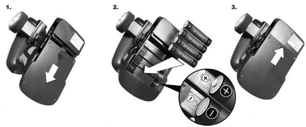
NOTE: Do not mix old and new batteries. Do not mix alkaline, lithium, standard (carbon zinc), or rechargeable (nickel- cadmium) batteries. Do not change or charge batteries in a hazardous location .
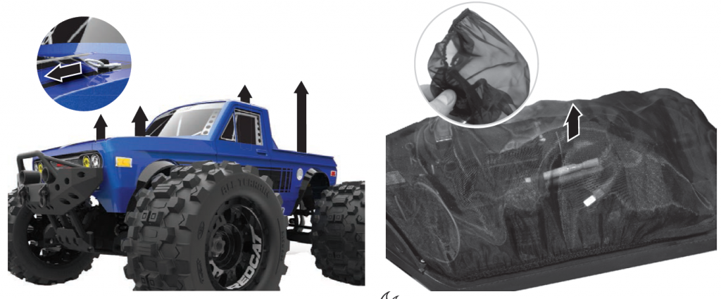
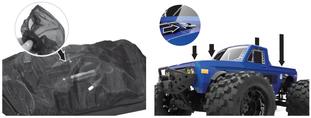
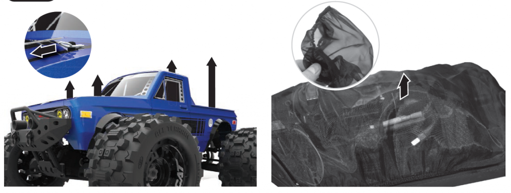
REMOVE BODY
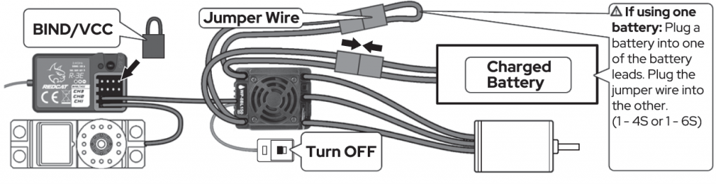
INSTALL FULLY CHARGED BATTERY PACK
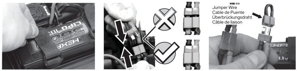
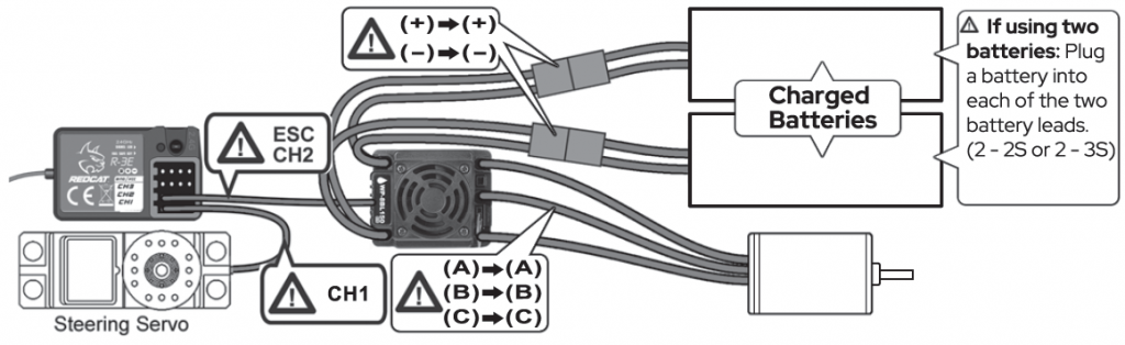
Attention: The Kaiju’s ESC is wired to use two 25 ( 4S total) or two 3S (6S total) battery packs. If you’d like to use a single 4S or 65 battery pack, you must install the Jumper Wire (included with your vehicle) to complete the circuit, otherwise the ESC won’t turn on.
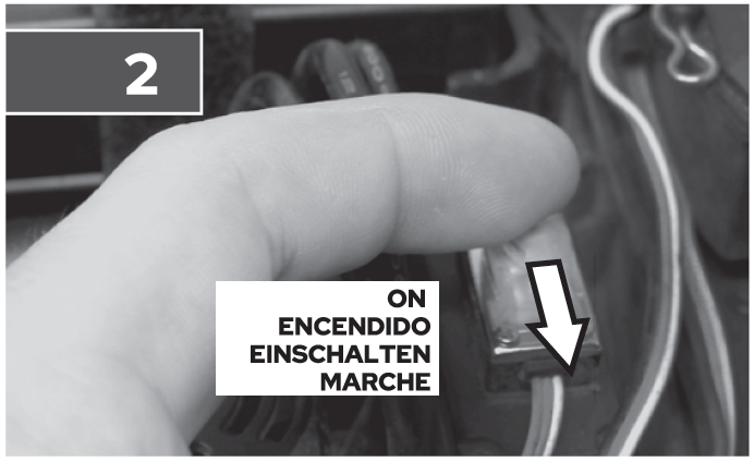
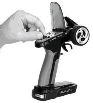
POWER ON
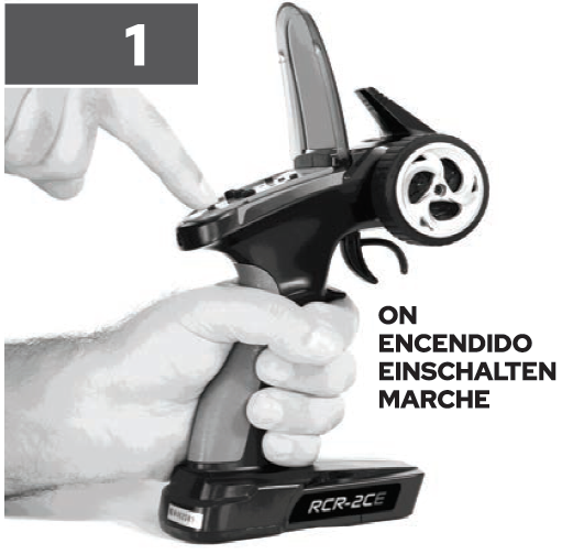
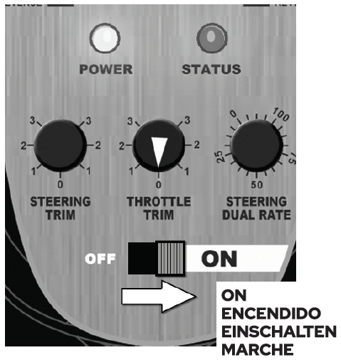
IMPORTANT: Be sure the throttle trim knob is set to ZERO. Leave the throttle trigger in the neutral position when turning on the radio and vehicle. Wait 3-seconds after turning on the vehicle before touching the transmitter controls.
INSTALL BODY
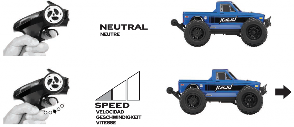
BASIC RADIO CONTROLS
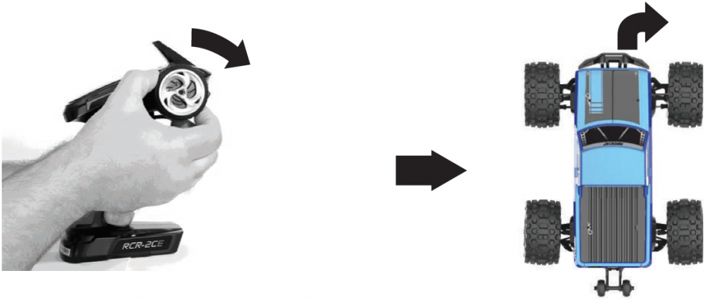
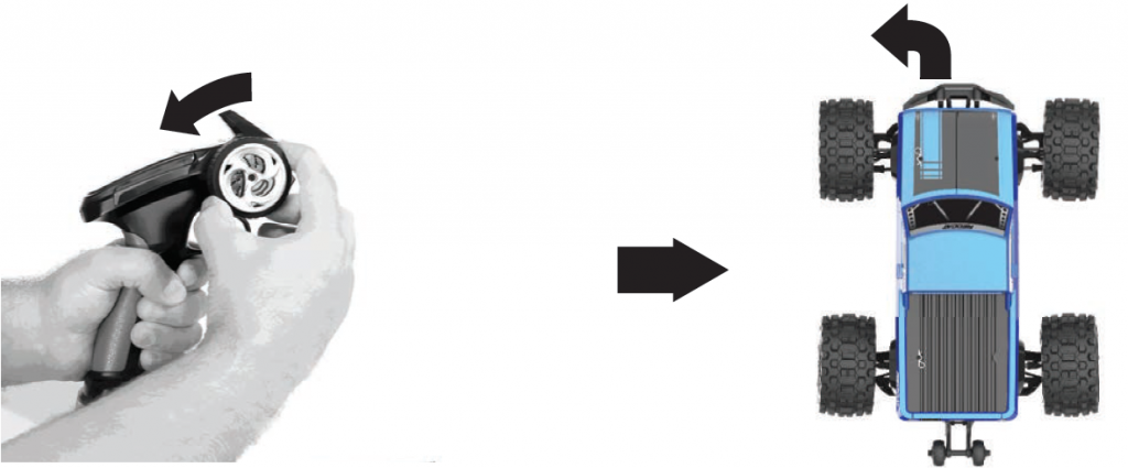
How to STEER
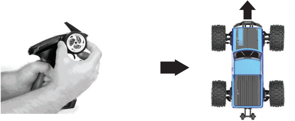
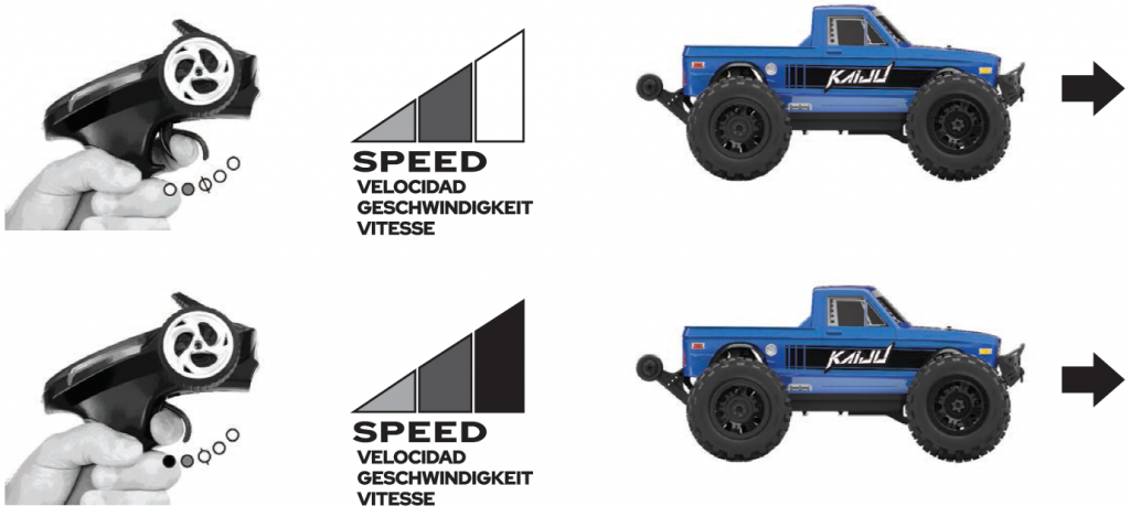
How to ACCELERATE
How to BRAKE
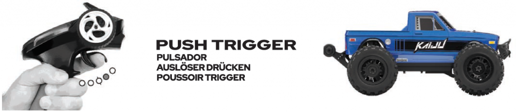
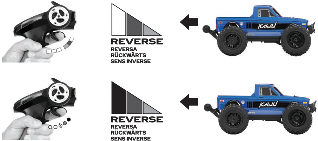
How to DRIVE IN REVERSE

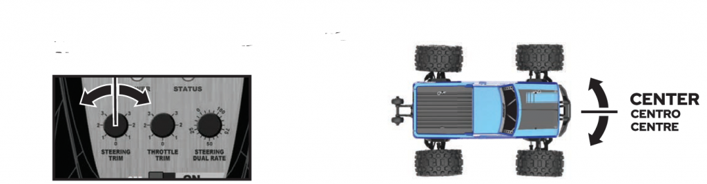
RADIO ADJUSTMENTS
Steering Trim – Steering Neutral
Throttle Trim – Throttle Neutral

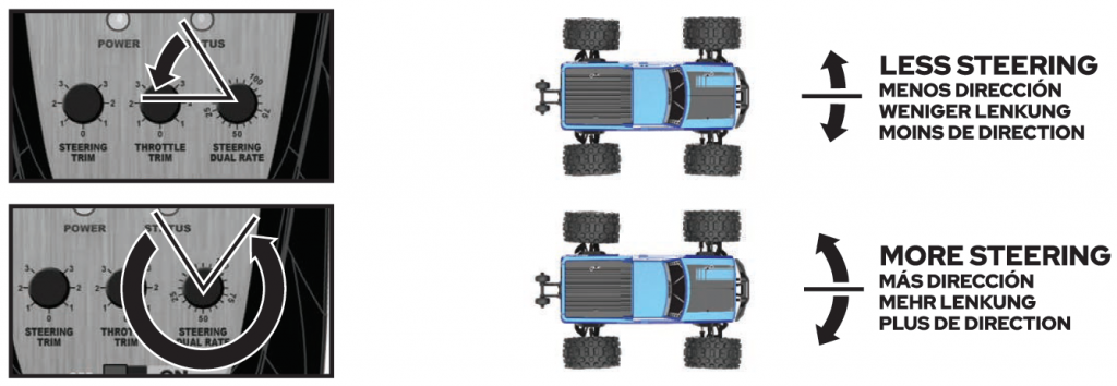
Steering D/R – Maximum Steering
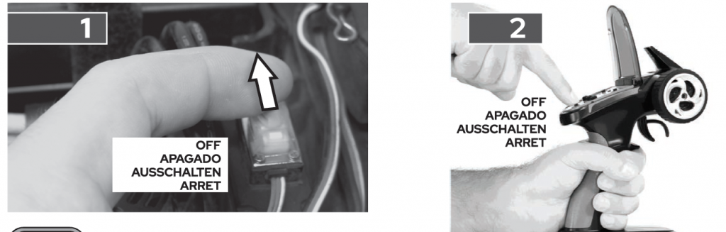
SHUTDOWN
REMOVE BODY
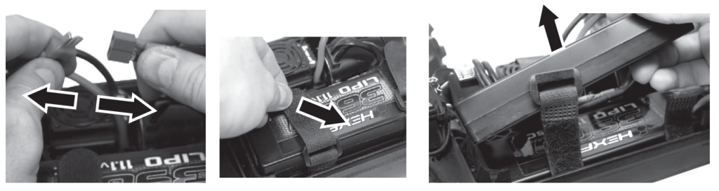
POWER OFF
REMOVE BATTERY
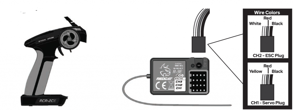
RADIO GUIDE
RADIO
Warnings and Compliance
FCC Compliance Statement! The radio included with your vehicle complies with part 15 of the FCC Rules. Operation is subject to the following two conditions: (1) This device may not cause harmful Interference, and (2) This device must accept any interference received, including interference that may cause undesired operations.
Note: This equipment has been tested and found to comply with the limits for a Class B digital device, pursuant to Part 15 of the FCC Rules. These limits are designed to provide reasonable protection against harmful interference in a residential installation. This equipment generates, uses and can radiate radio frequency energy and, if not installed and used in accordance with the instructions, may cause harmful interference to radio communications. However, there is no guarantee that interference will not occur in a particular installation. If this equipment does cause harmful interference to radio or television reception, which can be determined by turning the equipment off and on, the user is encouraged to try to correct the interference by one of the following measures:
- Reorient or relocate the receiving antenna.
- Increase the separation between the equipment and receiver.
- Connect the equipment into an outlet on a circuit different from that to which the receiver is connected.
- Consult the dealer or an experienced radio/TV technician for help.
IC ID: 24025 (please note that there maybe additional alpha numeric codes added to this number)This device complies with Industry Canada license-exempt RSS standard(s). Operation is subject to the following two conditions: (1) This device may not cause interference, and (2) this device must accept any interference, including interference that may cause undesired operations of this device.
WARNING:
- Any changes or modifications not expressly approved by the party responsible for compliance could void the user’s authority to operate this equipment.
- While operating the Radio, a separation distance of at least 20 centimeters must be maintained between the radiating antenna and the body of the user or nearby persons in order to meet the FCC RF exposure guidelines.
AFHDS (automatic frequency hopping digital system)AFHDS was developed for Radio control models and offers active and passive anti-jamming capabilities, low power consumption and high receiver sensitivity.
This radio system works in the frequency range of 2.405 to 2.475GHz. This band has been divided into 141 independent channels. Each radio system uses 16 different channels and 142 different types of hopping algorithm. By using various switch-on times, hopping scheme, and channel frequencies, the system is less likely to lose transmission.
Each transmitter has a unique ID. When binding with a receiver, the receiver saves that unique ID and can accept only data from that unique transmitter. This avoids picking another transmitter signal and dramatically increases interference immunity and safety.
WARNING: Even with the AFHDS technology, if the radio system is not used in accordance with this manual, it can still fail and cause serious injury. Be sure to read and understand this entire manual, as well as the manual that came with all other RC components you are using .
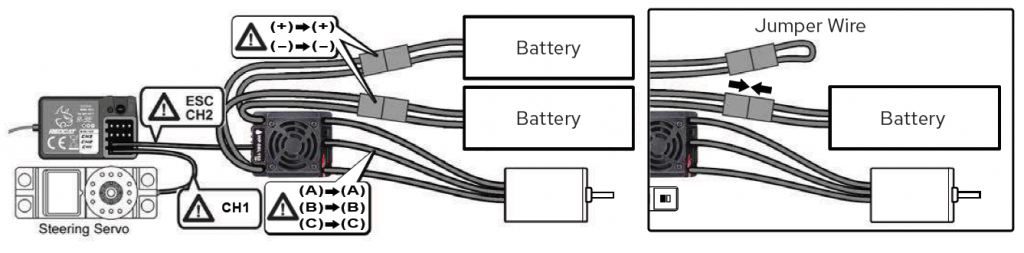
WIRING DIAGRAM
Receiver Connections
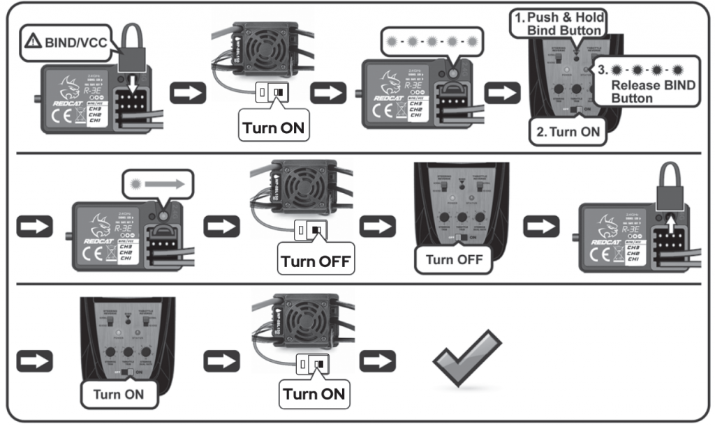
BINDING PROCESS
ESC GUIDE

NOTE: The cooling fans of ESC is supplied by the built-in BEC, so it is always working under 6V .
FEATURES:Completely water-proof and dust-proof.(Remove the cooling fan when running car in wet conditions. If the ESC gets wet, clean and dry thoroughly to avoid damage from the oxidation of copper connectors).
- External Programming Port (EPP), easily connect to a program card, and also works as power port for cooling fan.
- Excellent start-up, acceleration and linearity features.
- The built-in switching mode BEC is powerful enough to supply all electronic equipment with a reliable power source.
- There is a mounting stand for installing the ESC on chassis easily and firmly.
- Proportional ABS brake function with 5 steps of maximum brake force adjustment and 8 steps of drag-brake force adjustment. Also compatible with the mechanical disc-brake system.
- Multiple protection features: Low voltage cut-off protection / Over-heat protection / Throttle signal loss protection / Motor blocked protection.
WARNING:To avoid short circuits, ensure that all wires & connections are well insulated and there is proper contact at all connections. Read through the entire manual before operating and ensure all electronics are installed correctly. To avoid accidents, we recommend setting the vehicle on a stand, with the tires free from any contact, while connecting and adjusting electronics. Stop usage and unplug the battery immediately if the ESC exceeds 90ºC/194ºF as this may damage both the ESC and motor.Disconnect the battery after use. The ESC continuously draws current from the battery (even if the ESC is turned off). If left plugged in for long periods of time, the battery will completely discharge, which may result in damage to the battery or ESC. This WILL NOT be covered under warranty.
ERC
Calibration
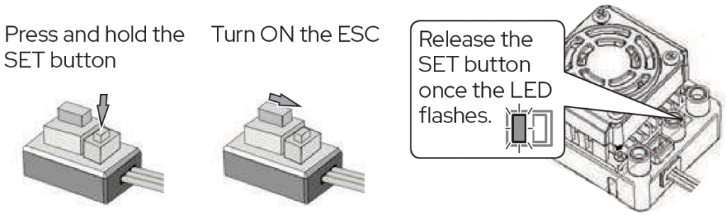
- Turn on the transmitter, set parameters on the throttle channel like “D/R”, “EPA” and “ATL” to 100% and the throttle “TRIM” to “0”. Disable the “ABS braking function”.
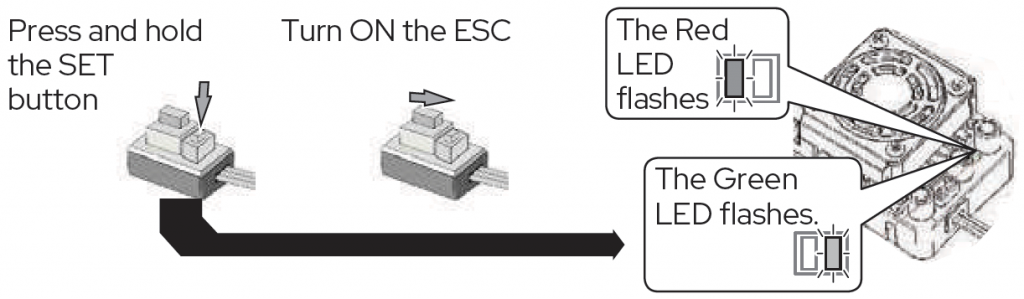
- Start with the transmitter on and the ESC turned off but connected to a battery. While holding the SET button, Turn ON the ESC, then release the SET button when you see the RED LED on the ESC start to flash(Note: the motor beeps at the same time). (The ESC will enter the programming mode if the SET button is not released within 3 seconds, which will then require you to restart from step 1.)
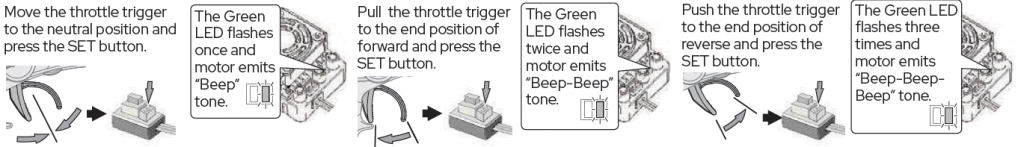
- To set the neutral point, leave the throttle trigger at the neutral position, press the SET button. The RED LED dies out and the GREEN LED flashes 1 time and the motor beeps 1 time to accept the neutral position.
- To set the full throttle endpoint, pull the throttle trigger to the full throttle position and press the SET button. The GREEN LED blinks 2 times and the motor beeps 2 times to accept the full throttle endpoint, then release the set button.
- To set the full brake endpoint, push the throttle trigger to the full brake position, press the SET button. The GREEN LED blinks 3 times and the motor beeps 3 times to accept the full brake endpoint. Release the trigger back to the neutral point. (The motor can be started 3 seconds after the ESC/Radio calibration is complete)
Programming
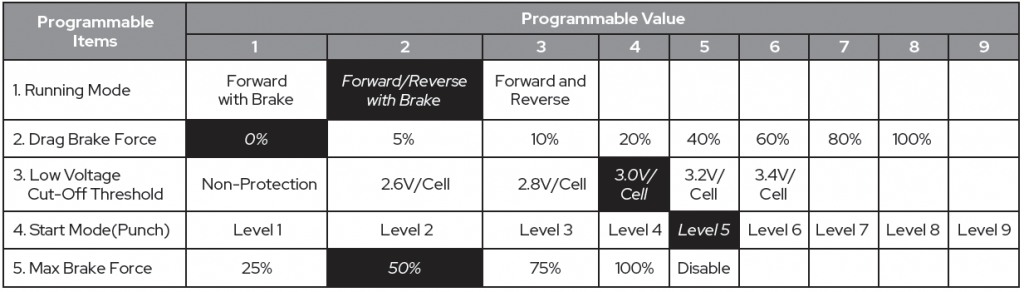
NOTE: The shaded boxes are default settings
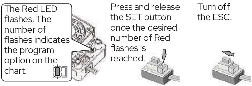
5. The Red LED will flash the number of times that corresponds to the number of the option listed along the top of the chart. (1 flash = Option 1, 2 flashes = Option 2, etc.)6. Press and release the set button until the desired number of Red flashes is achieved.7. To finish set up, turn OFF the ESC.8. You can now power the ESC back on. The settings should now be saved.9. Repeat steps 1-8 for each setting you wish to adjust.
Programming Flow Chart
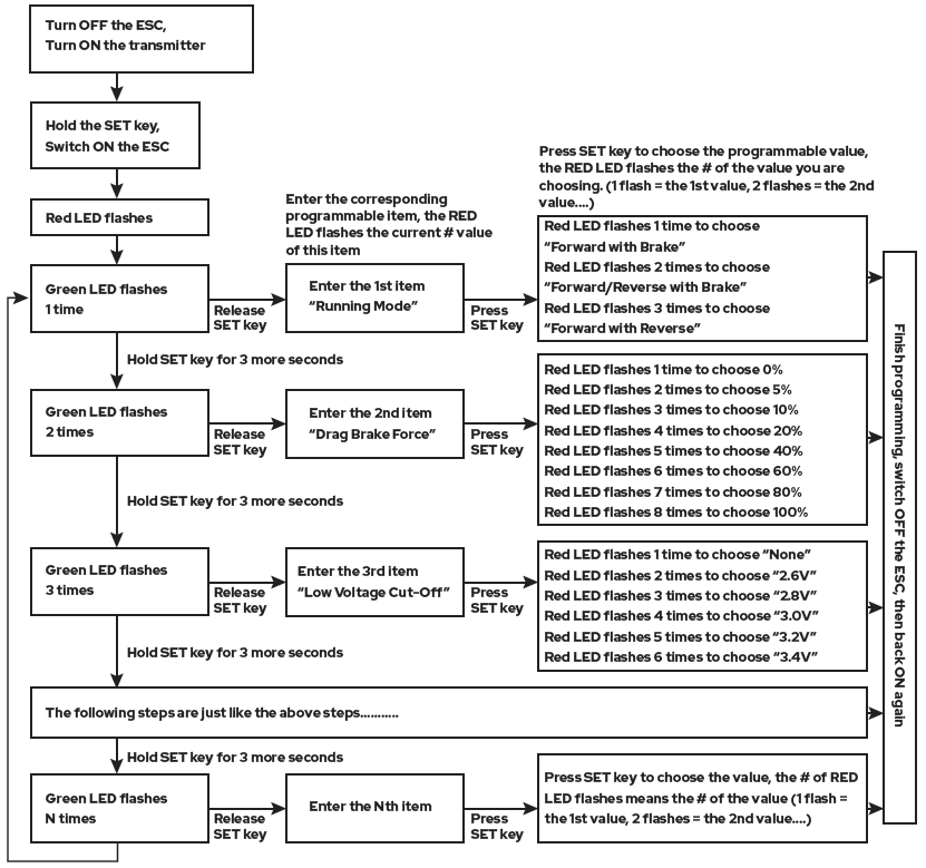
In the program process, the motor will emit a “Beep” tone when the LED flashes.A long flash and long “Beep—” tone is used to represent the number “5”, to easily identify items of a large number.
“A long flash” (Motor sounds “B—”) = the No. 5 item“A long flash + a short flash” (Motor sounds “B—B”) = the No. 6 item“A long flash + 2 short flashes” (Motor sounds “B—BB”) = the No. 7 item“A long flash + 3 short flashes” (Motor sounds “B—BBB”) = the No. 8 item“A long flash + 4 short flashes” (Motor sounds “B—BBBB”) = the No. 9 item
Programmable Items Description
- Running Mode: In “Forward with Brake” mode, the car can go forward and brake, but cannot go backward, this mode is suitable for competition. “Forward/Reverse with Brake” mode provides the reverse function, which is suitable for daily training.Note: “Forward/Reverse with Brake” mode uses “Double-click” method to enter reverse. When you move the throttle trigger from the forward zone to the reverse zone for the first time (The 1st “click”), the ESC begins to brake the motor, the motor slows down but it is still running, not completely stopped, so the reverse function does NOT happen immediately. When the throttle trigger is moved to the backward zone again (The 2nd “click”), if the vehicle is stopped, the reverse function will engage, driving the vehicle backward. The “Double-Click” method prevents accidentally sending the vehicle into reverse while trying to brake.Note: Any time during braking or reversing, if the throttle trigger is moved to forward zone, the motor will run forward at once.“Forward/Reverse” mode uses “Single-click” to make the car go backward. When you move the throttle trigger from forward zone to reverse zone, the car will go backward immediately. This mode is usually used for the Rock Crawlers and can be hard on the drivetrain.
- Drag Brake Force: Set the amount of drag brake applied at neutral throttle to simulate the slight braking effect of a brushed motor while coasting.
- Low Voltage Cut-Off: The function prevents the lithium battery pack from over discharging. The ESC detects the battery’s voltage at any time, if the voltage is lower than the threshold for 2 seconds, the output power will be cut off, and the red LED flashes: “˜-, ˜-, ˜-”.
- Start Mode (Also called “Punch”): Select from “Level 1” to “Level 9”. Level 1 has a very soft start (minimum wheel spin), while level 9 has a very aggressive start (maximum wheel spin). From Level 1 to Level 9, the start force increases. Please note that if you choose “Level 7” to “Level 9”, you must use a good quality battery with a high discharge rating (C-rating), otherwise these modes will just cause the motor to tremble and hesitate. If this is happening, lower the “Punch” level, or use a battery with a higher “C-Rating”.
- Maximum Brake Force: The ESC provides proportional braking. This setting increases or decreases the maximum amount of braking. On the lowest setting, the vehicle will gradually come to a stop while full brake is applied on the transmitter. On the highest setting, the vehicle will screech to a halt while full brake is applied on the transmitter. A high setting can potentially damage gears, so use caution while setting this option. The “Disable” option inhibits the inherent brake function of the speed controller. “Disable” is used mostly in nitro or gas vehicles using a mechanical disc-brake system driven by a servo.
Reset All Items To Default ValuesAt any time when the throttle is located in neutral zone (except in the throttle calibration or parameters program process), hold the “SET” key for over 3 seconds, the red LED and green LED will flash at the same time, which means each programmable item has be reset to its default value. The ESC will need to be restarted to complete the process.
Using an Optional Program Card (Not Included)The Program Card is optional equipment which needs to be purchased separately. It has 3 digital LEDs to display the programmable items’ number and the options’ number. (Please refer to the user manual of the program card for detail info)Attention! The Rx wire of the ESC (for connecting receiver) CANNOT be used to connect with the LED Program Card. Only use the fan port between the terminals ABC to connect the Program Card to the ESC.
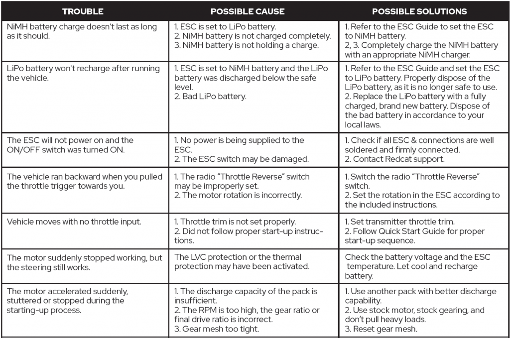
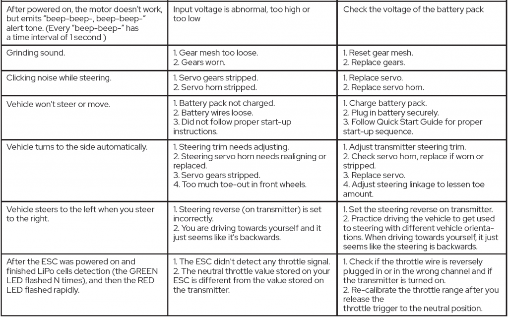
TROUBLESHOOTING
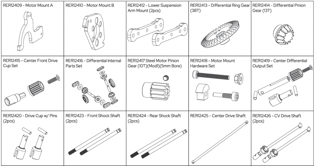
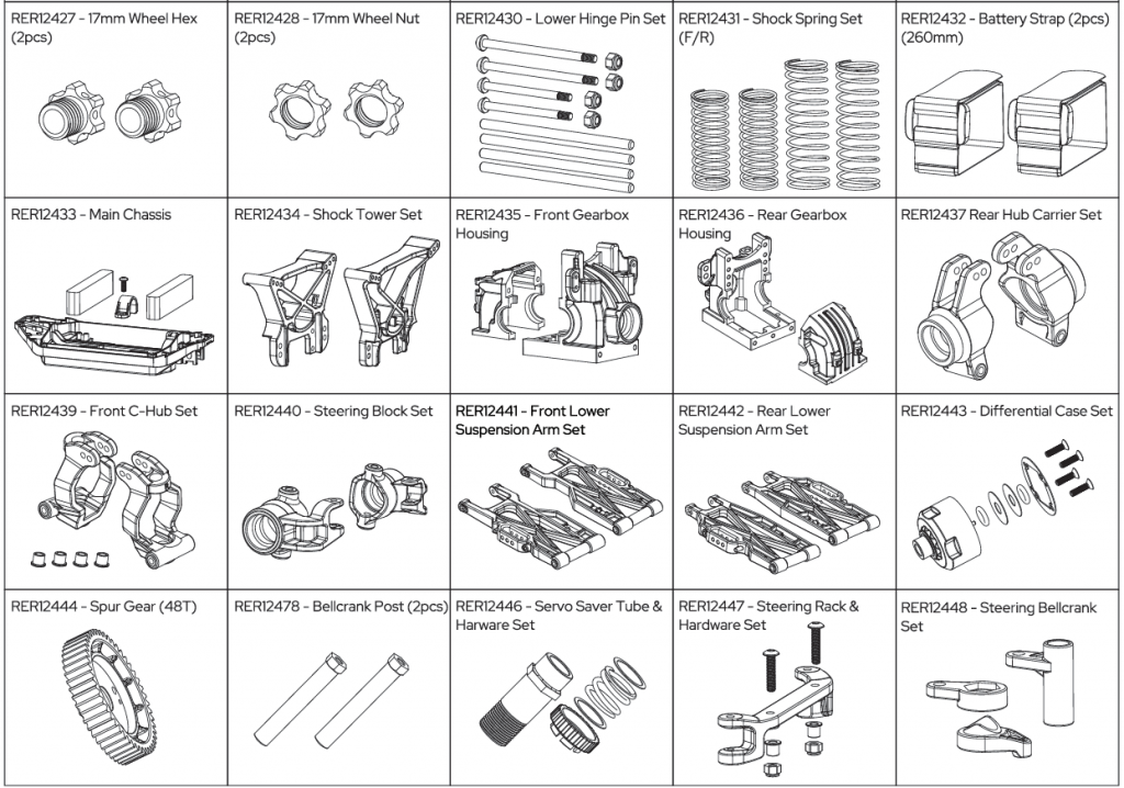
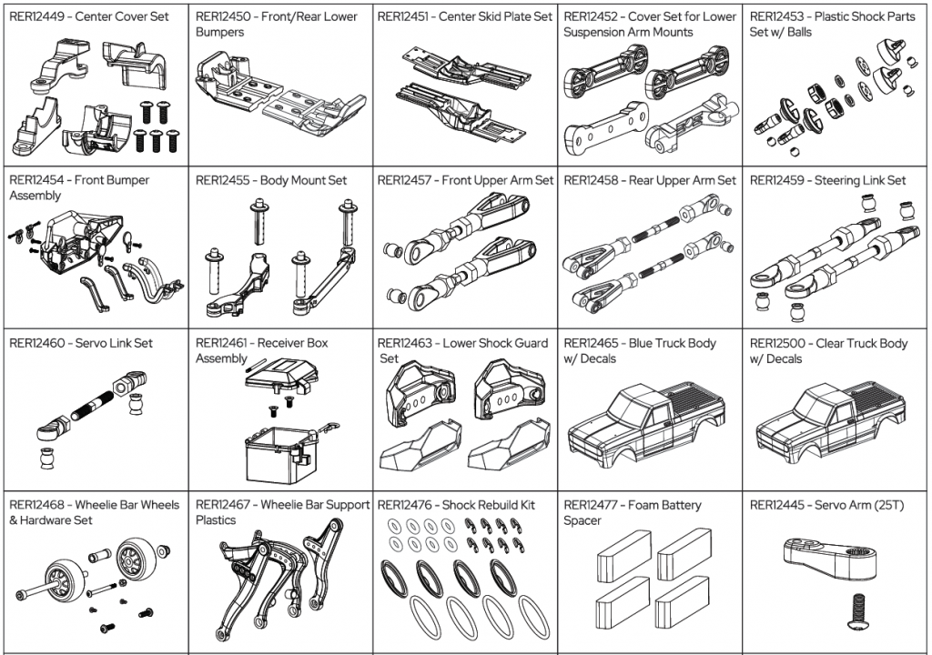
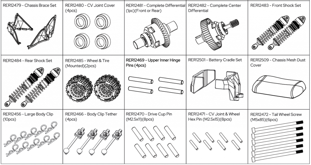
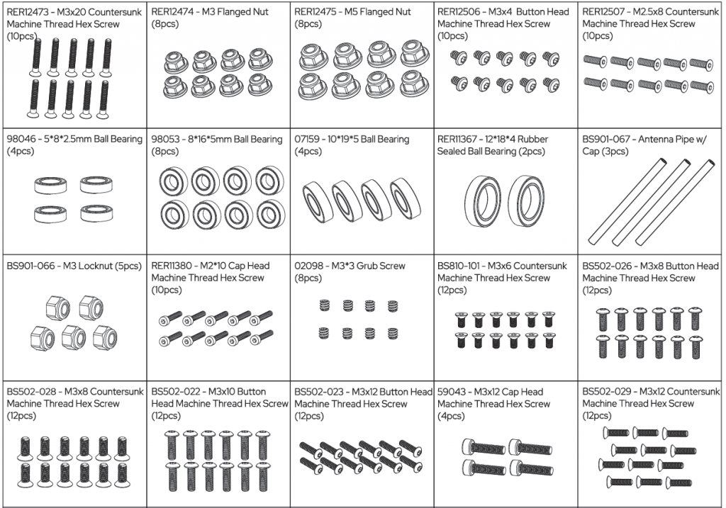
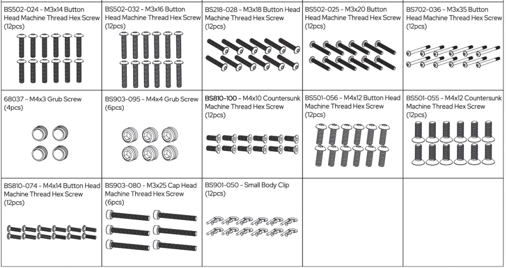
PARTS
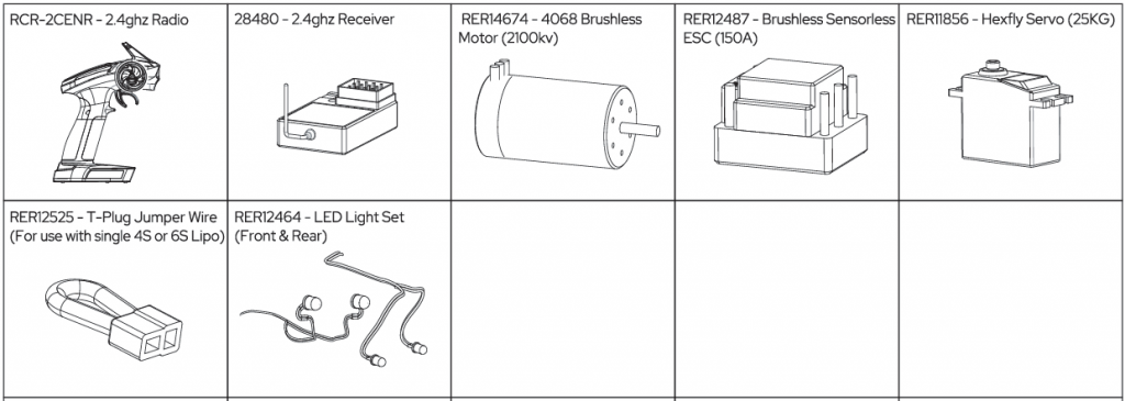
ELECTRONIC
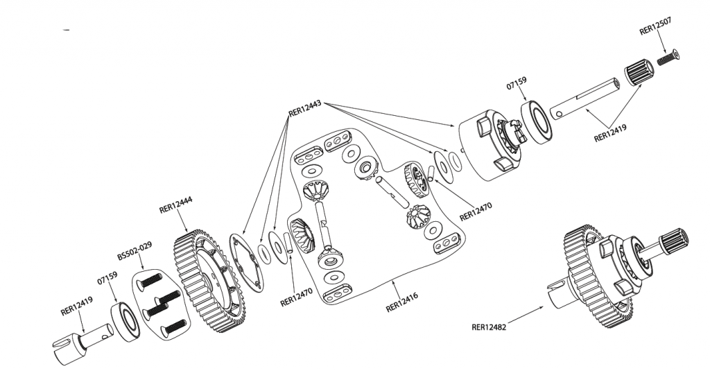
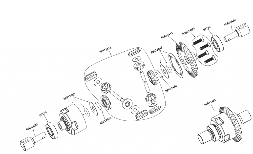
Exploded view
Center Differential
Front/Rear Differential
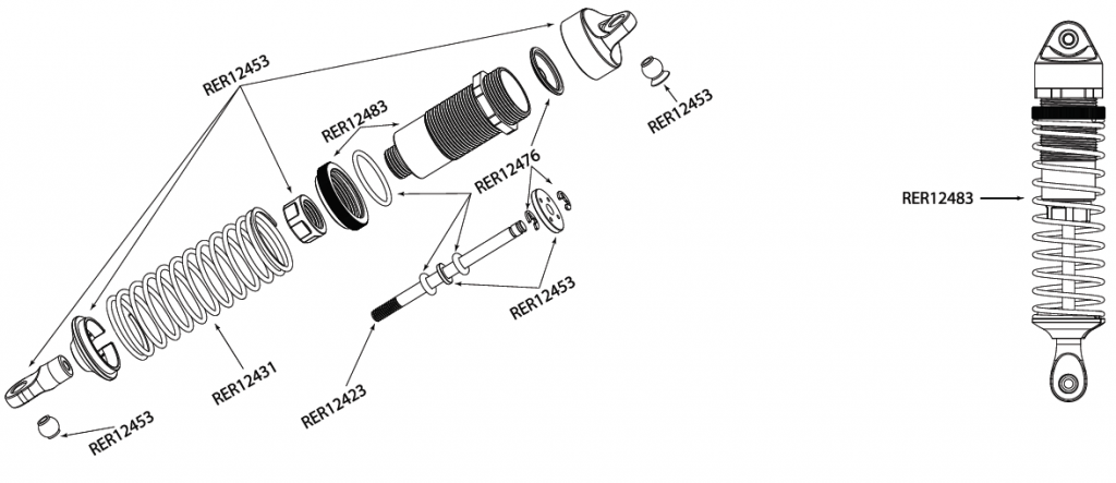
Front Shock
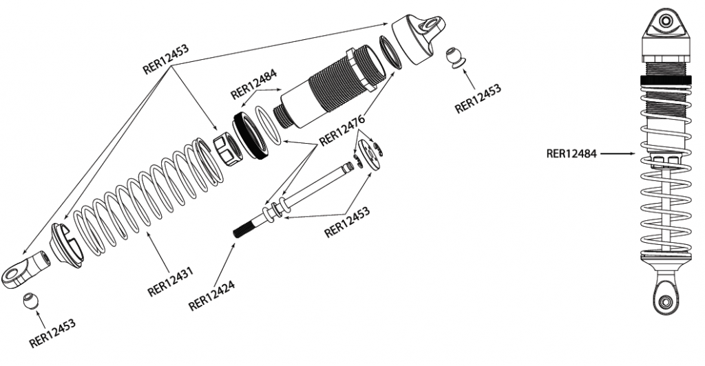
Rear Shock
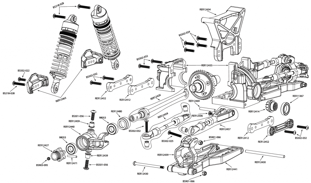
Front End
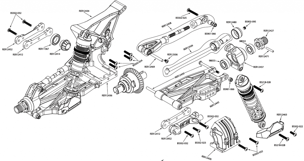
Rear End
www.redcatracing.comFollow us on social mediaTake a photo, create a video, post and share your Redcat experience.Stay up to date on the latest Redcat news, products, and creative content While these profiles are not customer service channels, you might find that one of our subject experts or another member of the community is able to assist you. If you have an issue or need technical and or product support, please reach out to Red cat directly through our website.
https://www.facebook.com/RedcatRacinghttps://www.instagram.com/redcatracing/https://www.youtube.com/RedcatRacinghttps://twitter.comjRedcatRacinghttps://www.pinterest.com/redcatracing/
IMPORTANT LINKS:
- Link to the most recent version of this manual with exploded views and parts lists: https://www.redcatracing.com/pages/manuals
- Link to electric vehicles manual: www.redcatracing.com/manuals/ELECTRIC-MANUAL.pdf
![]()
[xyz-ips snippet=”download-snippet”]