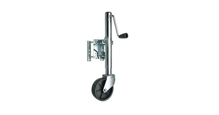
REESE Tongue Jacks User Manual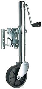
Read, Understand, Follow and Save These Instructions
Read, understand and follow all of these instructions and warnings (Instructions) before installing and using this product. Install and use this product only as specified in these instructions. Improper installation or use of this product may result in property damage, serious injury, and/or death. Never allow installation or use of this product by anyone without providing them with these instructions. You must read, understand and follow all instructions and warnings for any product(s) to which this product is used in conjunction with or installed. Save these instructions with the product for use as a reference for any future installation and use of the product.
WarningFailure to follow these warnings and instructions may result in property damage, serious bodily injury, and/or death
- Purchaser/owner must ensure that product is installed according these instructions. Purchaser/ owner must not alter or modify product.
- Operator and bystanders should never position any part of body under any portion of this product or the load being supported.
- Fully retract and rotate jack before towing
- When using the drop foot or drop leg, make certain the supplied pin is fully inserted through both sides of the inner tube and the drop tube before using the jack.
- If using optional drop foot or caster, always remove drop foot or caster before towing to maximize ground clearance.
- This product is not intended to be used as a transport device for the implement it is attached to. Minimize movement of implement while jack is under load.
- Do not allow children to play on or around this product or the load being supported
- Secure the load, vehicle and trailer from rolling (by blocking wheels) when operating jack or coupling trailer.
- Jack capacity is limited to the lesser of the jack, footplate, or caster wheel capacity.
- Never exceed maximum rated capacity. Refer to stamped markings or decals on product to obtain rated capacity. If uncertain, contact Sequent Performance Products at 1-800-632-3290 or www.cequentgroup.com.
- These jacks are designed for vertical loading. Excessive side forces may cause jack failure and must be avoided.
- Before manually moving trailer, crank to lowest position.
- If this product has a pivot tube mount, make certain the pivot pin is fully inserted through both sides on the pivot tube and the pivot mount.
- If this product is a swivel jack, lock the plunger pin into a hole in the mounting bracket before raising or lowering the tongue.
- Before installing the snap ring, inspect the snap ring groove and remove any debris. Seat the snap ring fully into the groove.
- Do not attempt to weld “Bolt-On” brackets or straps to the tongue. Special brackets are available for “Weld-On” applications.
- If this product has a drop foot or drop leg, never attempt to adjust the drop foot or drop leg when there is any load on the jack.
- If this product is a rack jack, do not raise the gear housing above inner tube.
- These jacks are not designed for mounting to round tongues.
- All welding must be performed by an AWS certified welder.
- Always replace bent, broken, or worn parts before using this product.
Installation Instructions
Warning: Failure to follow these warnings and instructions may result in property damage, serious bodily injury, and/or death.Before mounting the jack confirm that there will be no interference from the tow vehicle, tongue, ground, and any other mounted accessories while stationary or in motion. Before installing, check for interference in all positions including handle swing and swivel positions if applicable. Check for interference again after installation is complete.
Direct-Mount: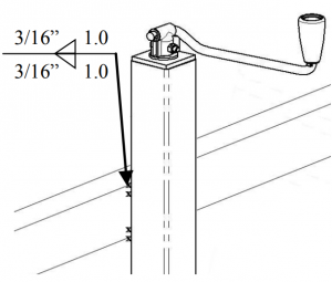 The same welding instructions apply to other weld-on mounts.
- All welding must be performed by an AWS certified welder.
- Place the jack at the desired location. Weld 1” in 2 locations on both sides of the jack using a 3/16” fillet weld.
Bolt-On Mounting Bracket Instructions:If using a bolt-on jack, assure the correct mounting hole pattern for your tongue size. The gap between the mounting bolts and the tongue is not to exceed 1/16”
- Place the jack against the tongue and position the mounting straps on the opposite side of the tongue. Align the holes in the mounting bracket with the holes in the mounting straps
- Insert the 4 bolts through the mounting bracket and mounting straps. The upper bolts should rest on the top of the tongue. The lower bolts should be less than 1/16” from the bottom of the tongue.
- Secure with locknuts, torque to 25 ft. lbs.
- Check for clearance of handle, trailer light cables, and coupler.


Snap Ring/Bolt-Thru Instructions:

- To attach a snap ring model jack, place the jack bracket over the mount and place the snap ring in the groove. Seat the snap ring fully into the groove.
- To attach a bolt-thru model jack, place the jack bracket into the recessed opening on the mount. Place the small end of bushing into the jack bracket and onto the bolt. Tighten locknut until there is little movement in the bushing. Note: The bolt should be installed between the trailer tongue and mount, the jack bracket will be held by the bushing between the locknut and the mount.
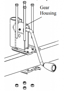
Bolt-on Rack Jack Instructions:
- Place the gear housing on the tongue, insert supplied bolts in holes corresponding to the tongue width.
- Place the mounting bracket below the tongue with the flat surface against the tongue.
- Secure with locknuts, torque to 25 ft. lbs
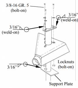
“A” Plate Mounting Instructions (Bolt-On or Weld-On):A-plate jacks are designed for mounting to trailers with A-plate couplers. It is recommended to attach a bottom support plate to the bottom of the tongue.
- All welding must be performed by an AWS certified welder.
- If the “A” plate is separate from the jack, align the jack (and foot, if equipped) with the jack and coupler as desired before welding. Use a 3/16” fillet weld.
- Bolt the jack “A” plate to the coupler. Use three 3/8-16 grade 5 bolts with washers, torque to 15-20 ft. lbs.
- Weld the recommended support plate to the bottom of the trailer frame. Use a 3/16” fillet weld.
- If your jack is a plain mount type, it may be mounted directly to a coupler with a 3/16” fillet weld. Align the foot (with the jack and coupler) as desired before welding
- Rack jacks with a similar “A” plate incorporated into their design may be attached according to these instructions

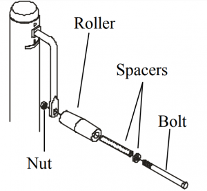
To attach a handle assembly:
- Insert the long spacer into the roller followed by the thin spacer and the bolt.
- Secure to the crank stem with the nut provided.
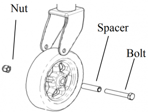
To attach a wheel assembly:
- Insert the long spacer into the wheel.
- Set the wheel into the caster body and place the bolt through the caster body and wheel.
- Secure with the nut provided.
To attach a top-wind handle assembly:
- Place the washer over the screw stem and then place the handle over the screw stem.
- Secure the handle to the screw stem with the bolt and nut provided.

Heavy Duty Caster:
- Jack capacity limited to lesser of jack or caster.
- Use 4 3/8” bolts, washers, and locknuts as shown.

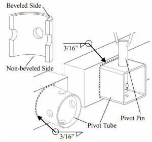
Weld-on Pivot Tube Mounting Instructions (Round and Square Pivot Tubes):
- All welding must be performed by an AWS certified welder.
- The non-beveled side of the pivot tube is welded to the tongue unless otherwise specified on hardware.
- Place the weld-on pivot tube against the tongue and weld all around with a 3/16” fillet weld. Align one set of pivot mount holes vertically.
- Mate the jack to the pivot tube and secure with the supplied pin.
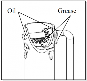
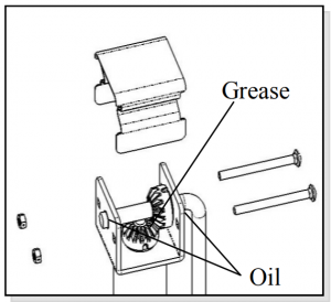
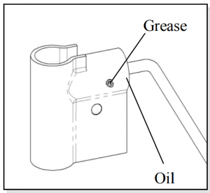
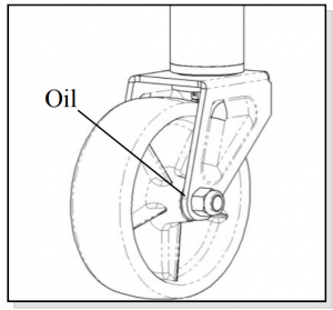
Maintenance
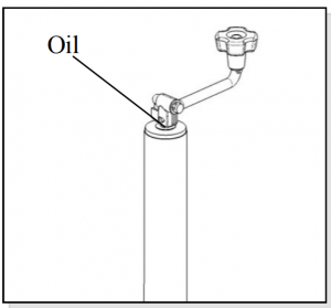
The following procedures should be performed at least annually: For side-wind models, the internal gearing and bushings of the jack must be kept lubricated. Apply a small amount of automotive grease to the internal gearing by removing the jack cover, or if equipped, use a needle nose applicator or standard grease gun on the lubrication point found on the side of the jack near the crank. Rotate the jack handle to distribute the grease evenly. A lightweight oil must be applied to the handle unit at both sides of the tube for side-wind models. If equipped, the axle bolt and nut assembly of the caster wheel must also be lubricated with the same light weight oil. For top-wind models, apply a lightweight oil to the screw stem. If this product is used in a marine environment, flush the jack assembly and bushings with fresh water, and apply fresh lubricant.
How to Order
Use only Cequent Performance Products’ parts or parts of equal quality for repair. Replacement parts are available through Cequent Performance Products’ Customer Service Department, 1-800-632-3290. Please specify product model number.
Limited Warranty
Limited Warranty. Cequent Performance Products, Inc. (“We” or “Us”) warrants to the original consumer purchaser only (“You”) that the product will be free from defects in both material and workmanship for a period of five years for Bulldog® and Fulton® products and one year for the Pro-Series® and Reese Towpower® products, ordinary wear and tear excepted; provided that installation and use of the product is in accordance with product instructions. There are no other warranties, express or implied, including the warranty of merchantability or fitness for a particular purpose. If the product does not comply with the applicable limited year warranty, Your sole and exclusive remedy is that We will replace the product without charge to You and within a reasonable time or, at our option, refund the purchase price. This warranty is not transferable.Limitations on the Warranty. This limited warranty does not cover: (a) normal wear and tear; (b) damage through abuse, neglect, t, misuse, or as a result of any accident or in any other manner; (c) damage from misapplication, overloading, or improper installation, including welds; (d) improper maintenance and repair; and (e) product alteration in any manner by anyone other than Us, with the sole exception of alterations made pursuant to product instructions and in a workmanlike manner.Obligations of Purchaser. To make a warranty claim, contact Us at 47912 Halyard Dr. Suite 100, Plymouth, MI 48170, 1-800-632-3290, identify the product by model number, and follow the claim instructions that will be provided. Any returned product that is replaced or refunded by Us becomes our property. You will be responsible for return shipping costs. Please retain your purchase receipt to verify date of purchase and that Youare the original consumer purchaser. The product and the purchase receipt must be provided to Us in order to process Your warranty claim.Remedy Limits. Repair or replacement is Your sole remedy under this limited warranty or any other warranty related to the product. We shall not be liable for service or labor charges incurred in removing or replacing a product or any incidental or consequential damages of any kind.Assumption of Risk. You acknowledge and agree that any use of the product for any purpose other than the specified use(s) stated in the product instructions is at Your own risk.Governing Law. This limited warranty gives You specific legal rights, and You also may have other rights which vary from state to state. This limited warranty is governed by the laws of the State of Michigan, without regard to rules pertaining to conflicts of law. The state courts located in Oakland County, Michigan shall have exclusive jurisdiction for any disputes relating to this warranty.
Contact us
7912 Halyard Dr. Suite 100Plymouth, MI 48170 USA800/632-3290www.cequentgroup.com

References
[xyz-ips snippet=”download-snippet”]