Regul8OR Digital High -Performance Programmable Power Supply Controller
MAGNET POWER SUPPLY SYSTEMS
REGUL8OR User’s ManualREGUL8ORDigital High-Performance Programmable Power SupplyControllerUser’s ManualAll Rights Reserved © CAEN ELS s.r.l. Rev. 1.2 May 20211
REGUL8OR User’s Manual
This product is
compliant.
CAEN ELS s.r.l. in AREA Science Park S.S. 14 km 163,5 loc. Basovizza 34149 Trieste (TS)Italy Mail: info@caenels.com Web: www.caenels.comRegistered office: via Vetraia 11 55049 Viareggio (LU) – Italy2
REGUL8OR User’s ManualUser’s Manual Models Options Custom ModelsThis manual covers the following standard REGUL8OR models:· REGUL8OR · REGUL8OR-PWMFor technical assistance please refer to the following contact: CAEN ELS S.R.L. SS14 km 163,534149 loc. Basovizza Trieste (TS), Italy (c/o Area Science Park Building Q1) Phone: +39 040 375 6610 Fax: +39 040 375 66113
REGUL8OR User’s ManualTable Of Contents1. INTRODUCTION………………………………………………………………………………….101.1 REGUL8OR OVERVIEW …………………………………………………………………… 10 1.2 REGUL8OR AT A GLANCE …………………………………………………………………13DCCT Direct Current Transducer………………………………………………..15 Digital Control Loop……………………………………………………………………..15 1.3 OPERATION MODES ………………………………………………………………………….. 17 Regulation Mode ………………………………………………………………………….. 17 Control Mode ………………………………………………………………………………. 17 Update Mode………………………………………………………………………………..18 1.4 EXTERNAL INTERLOCKS AND STATUS SIGNALS …………………………………….. 19 Interlock Enable/Disable Mask……………………………………………………….19 Interlock Activation Level Mask …………………………………………………….. 19 Interlock Intervention Time…………………………………………………………….20 Interlock Isolation ………………………………………………………………………… 20 Output Status Signal User-Defined……………………………………………….20 1.5 TRIGGER AND ANALOG CONTROL INPUTS……………………………………………..21 Trigger input ……………………………………………………………………………….. 21 Analog Control Input ……………………………………………………………………. 22 1.6 EXTERNAL SENSORS …………………………………………………………………………. 24 1.7 SYNCHRONIZATION OF MULTIPLE UNITS ……………………………………………… 25 1.8 EXTERNAL SPI………………………………………………………………………………….25 1.9 OUTPUT CONNECTORS ………………………………………………………………………. 26 1.10 INPUT VOLTAGE AND CURRENT CONNECTORS ………………………………………. 27 1.11 FRONT PANEL INDICATORS …………………………………………………………………28 1.12 INTERNAL PROTECTIONS…………………………………………………………………….29Regulation Fault ………………………………………………………………………. 29 OVerTemperature – OVT …………………………………………………………… 29 1.13 WAVEFORM ……………………………………………………………………………………..302. INSTALLATION ………………………………………………………………………………….. 312.1 PREPARATION FOR USE ……………………………………………………………………… 31 2.2 INITIAL INSPECTION ………………………………………………………………………….. 31 2.3 MOUNTING……………………………………………………………………………………….32Rack Mounting …………………………………………………………………………….. 32 2.4 AC INPUT POWER CONNECTION …………………………………………………………. 32AC Source Requirements ………………………………………………………………. 33 AC Input Cord………………………………………………………………………………33 2.5 EXTERNAL POWER SUPPLY CONNECTION …………………………………………….. 34 2.6 CABLE LENGTH…………………………………………………………………………………34 2.7 INTERLOCK AND STATUS SIGNALS ………………………………………………………. 36 2.8 EXTERNAL SENSORS …………………………………………………………………………. 39 2.9 EXTERNAL SPI………………………………………………………………………………….40 2.10 TRIGGER AND ANALOG CONTROL INPUTS ……………………………………………. 41 2.11 ISOLATED OUTPUT CONNECTORS ……………………………………………………….. 42 2.12 SYNC IN AND SYNC OUT………………………………………………………………..43 2.13 CURRENT AND VOLTAGE INPUTS ………………………………………………………… 44 2.14 INSULATION …………………………………………………………………………………….. 454
REGUL8OR User’s Manual2.15 MATING CONNECTORS……………………………………………………………………….46 3. LOCAL CONTROL ……………………………………………………………………………… 473.1 NAVIGATION SWITCH………………………………………………………………………… 47 3.2 DISPLAY…………………………………………………………………………………………..47Power-up …………………………………………………………………………………….. 48 Home Screen ………………………………………………………………………………..49 Menu Page ………………………………………………………………………………….. 51Control Page………………………………………………………………………….52 Config Page…………………………………………………………………………..53 Advanced Page………………………………………………………………………54 4. MECHANICAL DIMENSIONS……………………………………………………………..55 5. TECHNICAL SPECIFICATIONS ………………………………………………………… 565
REGUL8OR User’s Manual
Document Revisions
Revision
Date
1.0
October 2nd, 2020
1.1
October 7th, 2020
1.2
May 21st, 2021
First Release
Comment
Corrections made on several sections
Updated Local Control Section
6
REGUL8OR User’s Manual
Safety informationThe following table shows the general environmental requirements for a correct operation of instruments referred in this User’s Manual:
Environmental Conditions Environment Operating Temperature Operating Humidity Altitude Pollution degree Overvoltage Category Storage Temperature Storage Humidity
Requirements Indore use 0°C to 40°C 20% to 80% RH (non-condensing) Up to 2000 m 2 II -10°C to 60°C 5% to 90% RH (non-condensing)
The following symbols are used within this manual or are reported in the box and along this manual:
·
CAUTION Risk of Electrical Shock
·
Caution: Documentation must be consulted in all cases where
this symbol is marked
0 ·
Off (Power)
I ·
On (Power)
WARNING
·
The WARNING sign denotes a hazard. An attention
to a procedure is called. Not following the procedure correctly could result in
personal injury. A WARNING sign should not be skipped and all indicated
conditions must be fully understood and met.
7
REGUL8OR User’s Manual
CAUTION
·
The CAUTION sign denotes a hazard. An attention to
a procedure is called. Not following procedure correctly could result in
damage to the equipment. Do not proceed beyond a CAUTION sign until all
indicated conditions are fully understood and met.
CAEN ELS s.r.l. will repair or replace any product within the guarantee period if the Guarantor declares that the product is defective due to workmanship or materials and has not been caused by mishandling, negligence on behalf of the User, accident or any abnormal conditions or operations.
Please read carefully the manual before operating any part of the instrument
WARNINGDo NOT open the TOP COVER of the BOX
CAEN ELS s.r.l. declines all responsibility for damages or injuries caused by an improper use of the Modules due to negligence on behalf of the User. It is strongly recommended to read thoroughly this User’s Manual before any kind of operation.CAEN ELS s.r.l. reserves the right to change partially or entirely the contents of this Manual at any time and without giving any notice.8
REGUL8OR User’s ManualDisposal of the Product The product must never be dumped in the Municipal Waste. Please check your localregulations for disposal of electronics products.WARNING · Do not use this product in any manner not specified bythe manufacturer. The protective features of this product may be impaired if it is used in a manner not specified in this manual. · Do not use the device if it is damaged. Before you use the device, inspect the instrument for possible cracks or breaks before each use. · Do not operate the device around explosives gas, vapor or dust. · Always use the device with the cables provided. · Turn off the device before establishing any connection. · Do not operate the device with the cover removed or loosened. · Do not install substitute parts or perform any unauthorized modification to the product. · Return the product to the manufacturer for service and repair to ensure that safety features are maintained9
REGUL8OR User’s Manual
1. IntroductionThis chapter describes the general characteristics and main features of the REGUL8OR controller series.1.1 REGUL8OR OverviewThe REGUL8OR is a high-performance and high-stability digital controller and can be used with all the COTS (Commercial Off-The-Shelf) programmable power supplies that accept an analog control input ranging from:· 0 V … +5 V (UNIPOLAR) · 0 V … +10 V (UNIPOLAR) · -5 V … +5V (BIPOLAR) · – 10 V … +10 V (BIPOLAR)or a current 4-20 mA input to improve their specifications over different aspects.Thanks to the GUI (Graphic User Interface), the control and configuration of the REGUL8OR is straightforward, while the several interfaces present on the rear panel of the module allow for a quick and easy connection to the external power supply adding several functionalities.The extreme versatility of the device is given by the possibility to choose, on the same hardware module, between several current and voltage input ranges, as listed in the following Table 1.
Input Type Current [A] Voltage [V]
Ranges
± 100 ± 150 ± 200 ± 300 ± 400 ± 600 ± 1000
± 5
± 10
± 20
± 50 ± 100
Table 1: configurable ranges for the REGUL8OR
± 200
10
REGUL8OR User’s ManualThe REGUL8OR module is housed in a compact mechanical format and it fits in a single 19″ – 1U standard crate. The device implements a completely digital control loop with a 1-MSPS, 20-bit Digital-to-Analog Converter (DAC) that allows adapting the system to basically any general-purpose programmable power supplies. The behavior of device is schematically descripted in Figure 1:Figure 1: schematic representation of the REGUL8OR coupled to an external power supply. The digital controller generates a voltage analog signal to control the external power supply, which in turn acts as an amplifier and generates the current (or voltage) desired. The REGUL8OR then closes thevoltage and current loops and elaborates the values in a digital PID.The REGUL8OR is a digital control device that uses two 24-bit Analog-toDigital Converters (ADCs), one for the voltage input path and the other for the current input path, to sense the external current and voltage generated by the general-purpose power unit controlled, in order to compute them in a digital PID controller which in turn produces the analog voltage output (or the 4-20 mA) to control the COTS power supply.The control board houses a dedicated SoC (System on Chip), including an FPGA with an integrated dual-core ARM CPU. The loop regulation task is performed directly by the FPGA logic, in order to have high performance and deterministic loop control. An embedded Linux OS is installed on the ARM CPU, supervising all processes as well as communication, diagnostics and local interface handling.Remote communication is guaranteed by means of an Ethernet 10/100/1000 Mbit autosensing socket present on the front panel of the device on a RJ45 connector.11
REGUL8OR User’s ManualThe REGUL8OR can be also monitored and controlled via a navigation switch and a graphic high-resolution color display featuring user-friendly menus.In addition to the standard Ethernet interface, it is possible to communicate with the unit using the SFP-ports on the front panel. This interface allows communicating with the unit using a proprietary protocol (packet structure with a very high update rate (more than 10 kHz) for fast applications. These ports are connected directly to the FPGA logic and so the given packet is elaborated directly by the hardware logic.This approach eliminates the software stratification that manages the packet and the computational time is smaller and deterministic, allowing a very high update rate of the setpoint, giving the user more flexibility and excellent rates for the digital remote control of the power supply.12
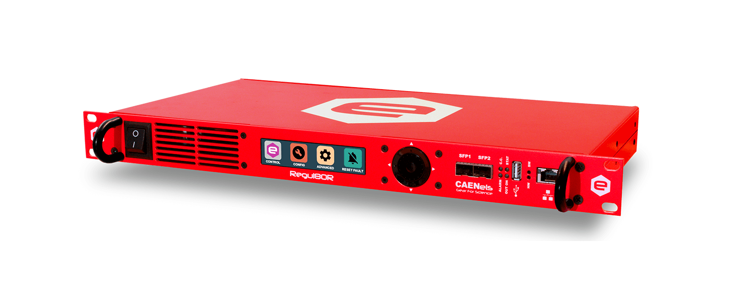
REGUL8OR User’s Manual1.2 REGUL8OR at a glanceThe REGUL8OR system is composed by a single 19-inch 1U crate. The unit and its I/O connections can be easily seen in Figure 2 (front view),Figure 3 (rear view) and Figure 4 (rear view with optical transmitters/receivers – optional).Figure 2: REGUL8OR front view On the front side of the REGUL8OR unit there are placed respectively: a power switch, a colour graphic display with navigation switch for the local control of the module, three communication sockets (2 SFPs and one Ethernet port), four status LEDs and one USB device connector.Figure 3: REGUL8OR rear view without opto-transmittersFigure 4: REGUL8OR rear view with optional opto-transmitters13
REGUL8OR User’s Manual
On the rear side of the unit are placed: AC power line input and all the connectors for the communication with other external devices. A brief description of the connector used are described in the Table 2.
Connector Name OpticalTransmitters andInterlocks [OPTIONAL]Interlocks andStatus SignalsTrigger InputSync In andSync OutExternal SPIExternal SensorsAnalog InputDCCT Current TransducerOutput Voltage DAC
Connector TypeD-SUB25 Isolated BNCSMA
DescriptionThere is the possibility to install 8 optical transmitter and 2 optical input receivers. This can be used to generate high resolution PWM signals to be fed to a power stage. Two optical input interlocks are also available e.g. interlocks from IGBT modules 6 external interlocks (four dry-contact types and two 24-V type ones) that can be used to capture external faults. Six signal status are also present on the same connector: 2 TTL signals (5 V), 2 magnetic relays with NO and NC contacts and 2 solid state relays Trigger Input connectors, can be used as a hardware start, or for the execution of a preloaded waveform Used to connect many power supplies in parallel or to synchronize their operation: SYNC IN and SYNC OUT signals is used to maintain different units in-phase.
8-pin
This connector allows to add new modules to
Right-Angle the REGUL8OR
D-SUB9 MaleIsolated BNCD-SUB9 FemaleIsolated BNC
Used to connect external sensors to the REGUL8OR, e. g. external temperature sensor or a hall probe. The control board can be controlled not only using the digital communication interface but also with an external analog signal. Input voltage range span from -10 V to +10 V (or can be selected 5 V range) Thanks to this connector an external DCCT, for the measure of the current, can be connected to the REGUL8OR BNC used to control the external power supply. The voltage output is also available on the LEMO connector together with the 4-20 mA output
14
REGUL8OR User’s Manual
Connector Name 4-20 mA DAC Voltage Input
Connector TypeLEMOIsolated Banana
DescriptionAllows using the REGUL8OR in a 4-20 mA control loopTwo isolated banana connectors are installed to sense the external voltage on the load
Table 2: short description of the connectors on the rear panel of the REGUL8OR
DCCT Direct Current TransducerTo achieve high performance in terms of stability and low noise in the current readout, and so on the current regulation, the REGUL8OR takes advantage of theDCCT transducers of the < series manufactured by CAEN ELS.The main characteristics of this technology are:· Extreme low-noise values; · Temperature Coefficient at sub-ppm level; · Monitoring of DC and AC current; · Galvanic insulation from the conductor to be measured i.e. currentcan be measured at a high voltage potential.The use of this technology greatly improves specifications respect to the most common requirements. The signal-conditioning network that converts the secondary current of the transducer to a voltage is then fed to the Analog to Digital Converter (ADC) is also a specific state-of-the-art know how.Digital Control LoopThe core of the system is PID controller which is completely digital and it uses state-of-art technology on the FPGA and the DAC to implement a controller able to adapt to and to obtain maximum performance from any external power supply and any load condition.
15
REGUL8OR User’s ManualFigure 5: schematic representation of the systemThe implementation of the digital control loop via the REGUL8OR adds flexibility to any analog existing system, allowing it to be tuned to any load condition easily and remotely.16
REGUL8OR User’s Manual1.3 Operation ModesThe REGUL8OR system has multiple features and multiple configurations that allow using the unit for a very widespread scenario of applications and with a large variety of loads.A brief summary of the basic configurations that the unit is able to handle are hereafter presented.Regulation Mode The REGUL8OR can be used as current-controlled or voltage-controlled bipolar or monopolar unit. The regulation types are:· C.C. mode: it is the Constant Current (CC) regulation mode. The device regulates the output current produced by an external power supply and set by the user;· C.V. mode: it is the Constant Voltage (CV) regulation mode. The device regulates the output voltage produced by the external power supply and set by the user.Control Mode The REGUL8OR unit can be controlled in three main different ways that are hereafter listed:· LOCAL control: the unit can be controlled directly via the front panel color display and the navigation switch. When the unit is set in LOCAL mode it is possible to perform readings and monitor from the remote interface but any setting command is denied;· REMOTE control: the unit is controlled via the TCP-IP Ethernet interface. The setting and control of the unit can be performed exclusively via this interface while monitoring is still possible from the local display;· FAST-INTERFACE control: this interface allows controlling the unit via a proprietary protocol over the SFP/SFP+ interfaces (optical or electrical) and it is meant to be used for very fast applications. Update rates of more than 10 kHz are reachable by using this communication channel.17
REGUL8OR User’s ManualUpdate Mode The current or voltage setting of the unit can also be performed in four different modes: · NORMAL: the update of the set-point (current or voltage, depending on theoperation mode i.e. CC or CV respectively) is performed as soon as a new set-point is received via the remote, local or fast interfaces · WAVEFORM: the update of the set-point is performed on a specific timing (defined as a “waveform” attribute, more information on the Waveform section) and it is done internally · TRIGGER: the set-point is updated by an external event i.e. a hardware trigger coming from the rear BNC connector · ANALOG INPUT: the unit is controlled by an external signal that is fed to the rear BNC connector. The unit acts as a C.C. or C.V. controller depending on the pre-set Regulation Mode18
REGUL8OR User’s Manual1.4 External Interlocks and Status SignalsThe system is provided with 6 (six) external interlock inputs that can be easily configured using the Web Interface (embedded in the power unit) or directly using the standard power supply commands. A description of the configuration of the external interlocks using the power supply commands is hereafter described.The REGUL8OR also presents 6 (six) output status signals that are divided into:· 2 (two) magnetic relays with the NO, NC and COMMON taps; · 2 (two) solid state relays with two contacts; · 2 (two) isolated TTL signals (0-5 V).All these signals can be connected with other internal signals or status’ (e.g. module ON, module OFF, all the interlocks and so on) to create automations.The configurability of the REGUL8OR series allows the users to decide what interlocks are enabled or not, to set the interlock “trip” level (i.e. low or high), the time of intervention (i.e. the time that an interlock signal has stay at the “trip” level before generating a fault condition) and to associate to each one an interlock name/identification.This configuration can also be set and read using the Web Interface (provided with the power module) or using the low-level device configuration commands, which allows setting the advanced configuration parameters. All interlocks are disabled by default.External Interlocks and Status Signals are available on a D-SUB 25-pin Female type on the rear panel of the REGUL8OR.Interlock Enable/Disable MaskThe REGUL8OR series external interlocks can be enabled or disabled by writing to the corresponding Interlock Enable/Disable Mask field of the advanced configuration parameters. Refer to “Remote Control Manual” for additional details.Interlock Activation Level MaskEach external interlock can be chosen to trip at HIGH or LOW logic level. The dry-contact interlocks are hardware-activated when the input pins and their corresponding return pin are shorted. The remaining two interlocks are hardwareactivated when there is no voltage between the input pins and their corresponding return pins. They are hardware-deactivated in case a 24-V voltage source is applied.19
REGUL8OR User’s ManualIt is necessary to write on the advanced configuration parameters with the Web Interface or via standard power supply commands in order to configure the interlock state mask.Interlock Intervention Time The module also allows to setting the interlock intervention time (the time that an interlock signal needs to be at its activation level before tripping and thus generating a fault condition). The parameters of the Intervention Time (expressed in milliseconds) are stored in the device memory.Interlock Isolation The interlock pins are galvanically isolated from ground and outputs terminal, nevertheless the absolute maximum voltage, referred to ground, that these pins can sustain is of 54 VDC. All the interlocks inputs have their own return connection.Output Status Signal User-Defined The solid-state relay signals (please refer to the I/O connector section for more information) can be remotely commanded by the user in order to change their states (open/shorted) for any specific customer application. Solid State Relay Terminals shall not float more than ±54 VDC above/below chassis ground and their maximum current rating should never exceed 400 mA. The Signal Status can be set by writing to the corresponding Signal Status Mask fields of the advanced configuration parameters (refer to the “Remote Control Manual”) as well.20
REGUL8OR User’s Manual
1.5 Trigger and Analog Control inputsThe standard version of the REGUL8OR includes inputs for a trigger signal and for an analog control on the rear panel.A brief description of these features and their functionalities is presented hereafter.
Trigger inputThe trigger input accepts TTL-compatible (5V) signals and should be driven by a low-impedance source or generator. The trigger input is galvanically isolated from ground and can float up to ±54 VDC respect to the chassis.The logic levels are subject to a hysteresis that allows guaranteeing correct operation of the trigger feature also in noisy installations/environment. The trigger voltage logic levels are listed in Table 3:
Logic Level
Value
Low-to-HIGH
> 3.5 V
High-to-LOW
< 1.5 V
Table 3: Trigger Logic Levels
CAUTIONThe absolute maximum rating for the Trigger Input signal is of 5.5 V (a higher voltage level applied to this input can seriously damage the device).A visual representation of the voltage levels for the trigger operation is presented in the following Figure 6
21
REGUL8OR User’s Manual
Trigger Input
6
ABSOLUTE MAXIMUM
5
4
HIGH LEVEL
Trigger Signal
3
2
LOW LEVEL
1
0
Figure 6: Trigger Thresholds
Analog Control InputAn input that allows the REGUL8OR to be controlled remotely with an analog signal is provided on the rear panel on an isolated BNC connector. This input is labelled as “AN. INPUT” and it accepts signals ranging from -10 V to +10 V.This isolated input acts as an input for a digital closed-loop amplifier and it generates a control output signal (for the external unit) which is proportional to the input signal.This means that the REGUL8OR will regulate the output at -100 % for a 10 V analog input voltage, a 0% for a 0 V analog input voltage and a +100 % for a +10 V analog input voltage.An example of the relation between the analog input signal and the output (can be either current or voltage, depending on the Regulation mode) is shown in Figure 7.In order to avoid drifts, offset and external noise pick-up it is always suggested to use the digital interface e.g. Ethernet to control the external power unit in order to get the best performance.
22
REGUL8OR User’s Manual
+100%
Analog Control
+10V
-10V
AN CTRL
OUTPUT -100%
Figure 7: ANALOG CONTRL vs OUTPUT of the general-purpose power supply controlled
Please note that the bandwidth of the analog control input is internally limited to approximately 25 kHz.
23
REGUL8OR User’s Manual1.6 External SensorsThe REGUL8OR is equipped with an input connector on the rear panel that allows users to connect different external sensors useful for sensing an external temperature or a magnetic field for example.Having two different voltage supplies (1.8 V and 3.3 V referred to chassis ground) for the external temperature sensor allows installing a variety of different temperature sensors. The analog value is then conditioned by a low-pass filtering network that has gain of ½ and a cut-off frequency of 68-Hz. Then analog signal is converted by 12-bit ADC.The REGUL8OR also includes an interface to supply and read an external Hall probe. Some Hall probes needs to be supplied by a constant-current source while others by a constant-voltage source: an internal relay selects the type of supply to be used to power-up the Hall probe with:· a constant voltage of 5 V OR· a constant current of 20 mA. This option can be configured via the Web Interface or via the correspondingdedicated configuration commands.Figure 8: schematic representation of the connection between the Regul8OR and external temperature sensor and Hall Probe24
REGUL8OR User’s Manual1.7 Synchronization of Multiple UnitsThe SYNC IN and SYNC OUT connectors on the rear panel of the device (both SMA type) allows connecting and synchronizing multiple REGUL8OR units. This feature permits users to keep two or more REGUL8OR units in-phase.The first unit will generate an internal clock signal that will be fed to the SYNC OUT connector and needs to be connected to the SYNC IN input of the following unit.The SYNC IN and SYNC OUT signals are meant only for this dedicated application and are ground-referred.Figure 9: schematic representation of a synchronization of multiple units1.8 External SPIAn isolated SPI interface is present on the rear panel of the REGUL8OR on an 8pin connector.This 4-wire SPI allows interfacing external devices to the unit in order to match specific applications.Beside the 4 wires of the SPI interface i.e. MISO, MOSI, SCLK and CS – on this connector are also present the pins for an isolated power supply rated a 2 W maximum. These voltage levels are isolated from chassis ground (they can float up to 54 VDC) and they are rated at 5 VDC respect to the SPI ground pins.As an example, it could be possible to custom-design a 32-channel temperature readout external module with a small microcontroller and this external module could directly be powered and read by connecting it to this SPI interface connector (all firmware and software would need to be developed).25
REGUL8OR User’s ManualFigure 10: schematic representation of a connection between the Regul8OR and a generic external device made with the SPI1.9 Output ConnectorsThe REGUL8OR has been designed to control an external power stage/programmable power supply with an analog output voltage or, in specific cases, an analog output current (to close a 4-20 mA loop).Two connectors, an isolated BNC (voltage output) and a 4-pin LEMO (current path and voltage output), are provided on the rear panel to feed the isolated output signals.Typically, a general-purpose programmable power supply can be controlled via an external analog voltage with typical values ranging from 0 V to 10 V or from 0 V to 5 V (unipolar operation). In some specific applications, these signals can range from 10 V to +10 V or from -5 V to +5 V (bipolar operation).The analog output voltage is generated by a state-of-the-art 20-bit 1-MSPS Digital to Analog Converter (DAC).The 4-20 mA current control loop is often used in industrial process control. Its name refers to the current range used to control or to measure in the loop, where the current spans from a minimum value of 4 mA (0 %) to a maximum value of 20 mA (100 % or full-scale). The main reason for the use of this current-based signal has to be found in the fact that current signals are less sensitive to noise than voltage signals and are so sometimes preferred in noisy environments e.g. industrial facilities. The chosen loop driver is a single-channel, 16-bit converter.26
REGUL8OR User’s Manual1.10Input Voltage and Current connectorsThe output current and the output voltage are sensed by connectors placed on the device rear panel. The current is measured with a proprietary DCCT supplied and connected from/to a DSUB9 female connector. This cable is supplied together with the REGUL8OR unit.The voltage, on the other side, is voltage is sensed using two isolated banana connectors.Both current and voltage values are conditioned with two independent analog and digital networks that can be configured to read different ranges so to optimize the regulation performance on several types and ratings of external power stage or programmable power supplies.27
REGUL8OR User’s Manual1.11Front Panel IndicatorsThe REGUL8OR has four (4) front panel LED indicators as shown in the following Figure 11.Figure 11: front panel indicators The front panel indicators and their behaviour are hereafter listed (clockwise starting from top-left): · C.C.: Constant Current mode (blue). If turned on, the REGUL8OR is working in constant-current (CC) mode. When off, it is regulating in constant-voltage (CV) mode; · STAT (green): signals the correct operation of the module diagnostics. The blinking signaling the correct operation has a 1-second period; · OUT ON (blue): it signals if the output is enabled or not. The blue LED is on if the output is enabled and it is regulating output current or voltage; · ALARM (red): if turned on signals that the power unit has experienced a fault condition. It is necessary to perform a “reset fault” command in order to turn off this LED and to turn to module output again (only if the fault condition/cause has been removed).28
REGUL8OR User’s Manual1.12 Internal ProtectionsThe REGUL8OR is equipped with internal protections that allow configuring the unit for optimal operation. These protections have the dual use of protecting the unit and the connected load/external power unit/device from unwanted damages or undesired operation conditions.A brief description of the REGUL8OR internal protections is hereafter presented with some more basic considerations on their operation and use.Regulation FaultThis fault is generated when the power supply is not able to correctly regulate the output current or the output voltage (in C.C. and C.V. mode respectively).Different thresholds for the differential current, differential voltage and the intervention time can be set by experienced users.A typical example of a regulation fault is represented by a 10- load on a general-purpose power supply rated at 300 A and 50 V where the maximum power supply output voltage is 50 V. By setting a current of 10 A to the load, the output voltage should reach a value of 100 V which obviously is not feasible: once the power unit supplies 5 A to the load it already reaches the maximum output voltage condition. The REGUL8OR digital controller recognizes this difference between the set-point i.e. 10 A and the actual output current, thus generating a “regulation fault” condition.The tripping of this fault implies an automatic turning off of the REGUL8OR unit and the general-purpose power supply (if there is the possibility to shut down the external unit with an external signal). A status reset i.e. reset faults needs to be performed in order to turn the unit back on.OVerTemperature – OVTExternal monitoring of temperature is performed by using an external temperature sensor connected to the External Sensor Connector (see Chapter 2.8). If the temperature reading is exceeding a pre-defined threshold, an OVT condition is generated.The threshold value [°C] can be set by experienced users. A reset fault operation needs to be executed on the status register of the REGUL8OR before turning the output off again.29
REGUL8OR User’s Manual1.13 WaveformThe REGUL8OR is also able to act as a waveform generator both in constantcurrent (CC) and in constant-voltage (CV) regulation modes.The waveform is stored internally in a point-by-point scheme and it gives a lot of flexibility since the maximum number of points of the waveform can be defined as well as the sampling period (of the waveform execution).The minimum time interval for the waveform execution period is rated at 0.1 ms = 100 µs, giving an equivalent output waveform update rate of 10 kHz.In order to correctly execute the output waveform, it is necessary to “tune” the PID regulator parameters of the entire system i.e. REGUL8OR + external power supply to the specific load.More information on the waveform feature can be found in the corresponding command section.30
REGUL8OR User’s Manual
2. Installation
This chapter contains the basic instructions for initial inspection and preparation for use of the REGUL8OR.
2.1 Preparation for UseIn order to be operational, the REGUL8OR must be connected to an appropriate AC source. The AC source voltage should be within the device specification. Do not apply power before reading, Section 2.2 and 2.4 Table 4 below, describes the basic setup procedure. Follow the instructions in Table 2.1 in the sequence given to prepare the power supply for use.
Step
Checklist
Description
1
Initial inspection
Physical inspection of digital controller
2
Mounting
Installing the digital controller, ensuring proper ventilation
3
AC Input Power Connection
Connect the digital controller to the AC source
5
Power Supply connection
Connect the digital controller to the external power supply
4
First switch-on
Switch-on checkout procedure
Table 4: Installation checklist
2.2 Initial InspectionPrior to shipment, this digital controller was inspected and found free of mechanical or electrical defects. Upon unpacking of the digital controller, inspect for any damage which may have occurred in transit.
31
REGUL8OR User’s ManualThe inspection should confirm that there is no exterior damage to the digital controller such as broken switch or connectors and all the panels and display are not scratched or cracked. Keep all packing material until the inspection has been completed. If damage is detected, compile the RMA form available from the CAEN ELS website.2.3 MountingThe REGUL8OR module can be used either as a desktop unit or as a rack-mount device since the unit form factor is designed to be installed in a standard 19-inch cabinet (1U space occupation).CAUTION This unit is natural air-cooled; ventilation holes are present on the front and rear panel. Allow minimum 10 cm of unrestricted air space at the front and the read of the unit.Rack Mounting The REGUL8OR units are designed to fit in a standard 19″ equipment rack.CAUTION Use mounting rails to provide adequate support for the unit.NO2.4 AC Input Power ConnectionThe AC line input connector on the rear panel is a standard IEC 60320 C20 male inlet socket. Mains fuse holders are on the bottom part of the connector; required fuses characteristics for all the models are (T2AL250V):32
REGUL8OR User’s Manual· Size: 5 x 20 mm · Current rating: 2 A · Blow characteristic: Time delay · Breaking Capacity: 35 A · AC Voltage rating: 250 VFigure 12: AC Power Line input socketAC Source Requirements The REGUL8OR controllers are designed for universal AC input range since it can operate with voltage from 90V to 240V and input frequency ranging of 50 Hz or 60 Hz. Installation Category shall be CAT II so maximum impulse voltage on the network mains must be below 2500 V.AC Input Cord All the REGUL8OR digital controllers are directly shipped with the corresponding power cord (suitable for the destination country of the purchase). Power supply side connector is a standard IEC 60320 C19 plug. Current rating for the connector is 2 A. Wire size for detachable power supply cord, not longer than 2 m, shall be at least 0.75 mm2.WARNING There is a potential shock hazard if the power supply chassis is not connected to an electrical safety ground via the safety ground in the AC input connector!33
REGUL8OR User’s Manual2.5 External Power Supply Connection
WARNING
Turn off the AC input power (of both REGUL8OR and external power supply) before making or changing any rear panel connection. Ensure that all connections are securely tightened before applying power. There is a potential shock hazard when using a power supply with a rated output voltage greater than 60 V.The REGUL8OR needs a DCCT and an external power unit to work correctly. In the device shipping box are included all the cables necessary to connect the digital controller to the DCCT. If the REGUL8OR is bought together with the external power supply also the connections to the external device are included. Table 5 describes the cables in the shipping box:
Cable DCCT Voltage DACInterlock and signal status External Voltage
DescriptionCable for the connection of the DCCT to the REGUL8OR, to read the current Connect the output analog signal to the power unit to control it [OPTIONAL] Necessary to read the external interlock and to apply the signal status to the external power unit. [OPTIONAL]External voltage reading [OPTIONAL]
Table 5: description of the cable in the shipping box
WARNINGTurn off the AC input power (of both REGUL8OR and external power supply) before setting or changing the DCCT. Set the digital controller (and the power unit) in OFF state to connect or disconnect the DAC control cable for the external power supply. Ensure that all connections are securely tightened before applying power.2.6 Cable Length
34
REGUL8OR User’s Manual
In the table below – Table 6 – are listed the recommended length for the cables that will be connected to the device.
Cable
Length
Output voltage DAC cable
< 3 m
Output current DAC cable
< 30 m
DCCT cable Analog Input Cable
< 3 m < 30 m
Input voltage cables Sync In and Sync Out cable
< 30 m < 3 m
Trigger Input cable Opto-Transmitter
< 3 m Not Applicable
Table 6: Recommended cable lengths
35
REGUL8OR User’s Manual
2.7 Interlock and Status SignalsThe REGUL8OR module has four configurable dry-contact input interlocks, two 24-V interlocks, and six output status signals that are directly available on the DSub 25 Pin Female connector on the rear panel (Figure 13).A mating connector, a standard D-SUB 25-Pin Male type, can be installed in order to use/access these available signals.
Pin #13
Pin #1
Pin #25
Pin #14
Figure 13: Interlock and Signal Status Connector
The pinout of the D-SUB 25 rear connector is summarized in the following table (Table 7):
Pin Number #1 #2 #3 #4 #5 #6 #7 #8 #9 #10 #11 #12 #13 #14 #15 #16 #17
Description TTL reference Magnetic Relay #1 Center Tap (CT) Magnetic Relay #2 Normally Closed (NC) Magnetic Relay #2 Normally Open (NO) Solid State Relay #1 – Terminal 2 Solid State Relay #2 – Terminal 2 Interlock #6 negative input Interlock #6 positive input Interlock #5 positive input Interlock #3 positive input Interlock #4 positive input Interlock #2 positive input Interlock #1 positive input Magnetic Relay #1 Normally Closed (NC) Magnetic Relay #1 Normally Open (NO) Magnetic Relay #2 Center Tap (CT) Solid State Relay #1 – Terminal 1
36
REGUL8OR User’s Manual
Pin Number #18 #19 #20 #21 #22 #23 #24 #25
Description Solid State Relay #2 – Terminal 1 TTL Signal 2 Output 5 V (Reference signal pin #1) TTL Signal 1 Output 5 V (Reference signal pin #1)Interlock #5 negative input Interlock #3 negative input Interlock #4 negative input Interlock #2 negative input Interlock #1 negative input
Table 7: D-sub 25 Pin pin-out
WARNINGMagnetic Relay Contact (C-TAP, NO-TAP & NC-TAP) and Solid-State Relay Terminals (Terminal #1 & #2) shall not float more than ±54 VDC above/below chassis ground. Interlocks input and return pins shall not float more than ±54 VDC above/below chassis ground.CAUTIONVoltage between relay C-TAP and NC-TAP or NO-TAP pins shall never exceed ± 54 V. Maximum current rating for the Magnetic Relays is 1 A; current trough pins #CT and #NC or pins #CT and #NO shall never exceed 1 A. Maximum current rating for the Solid-State Relays is 400 mA; current trough pins #Terminal1 and #Terminal2 shall never exceed 0.4 A. Do not apply voltage between any input interlock dry contact and its corresponding return.The interlock pins are galvanically isolated from the chassis ground and outputs terminal, nevertheless the absolute maximum voltage, referred to chassis ground, that pins can sustain is 54V. The two interlocks inputs have their own return connection. The interlock is hardware-activated when the input pin and its corresponding return pin are shorted.
37
REGUL8OR User’s Manual
Relay Magnetic #1
Pins #14-2-15
Maximum Current
Max Voltage (to chassis ground)
1 A
54 V
Max Voltage (betweenpins)54 V
Magnetic #2
#3-16-4
1 A
54 V
Solid State #1
# 17-5
400 mA
54 V
48 V
Solid State #2
#18-6
400 mA
54 V
TTL Signal #1
#19-1
10 mA (4 mA recommended)
54 V
TTL Signal #2
#20-1
10 mA (4 mA recommended)
54 V
5.5 V 5.5 V
Table 8: Ratings of magnetic and solid-state relays and for TTL signals
38
REGUL8OR User’s Manual2.8 External SensorsThis connector (Figure 14) allows the user to connect external sensors to the REGUL8OR. Two pins are dedicated to supply an external voltage, one rated at 1.8 V and the other one rated at 3.3 V for a temperature sensor/transducer, one pin is dedicated to supply a 5-V voltage or a 20-mA current (can be selected via the Web Interface or via the relative configure commands for example for a Hall-probe), four chassis-ground (GND) pins and two pins for the input signals of the external sensors (one for a temperature sensor and one for Hall probe). The pinout of the D-SUB 9 rear connector is listed in Table 9
Pin 1
Pin 5
Pin 6
Pin 9
Figure 14: External Sensors input connector
Pin Number #1 #2#3, #4, #7, #8 #5 #6 #9
Description Temperature voltage supply +1.8 VTemperature voltage supply +3.3 VGND (chassis ground) Supply for a Hall-probe: Voltage source (5 V) or Current source (20 mA) External Input (Temperature Sensor 0 V/ +1.8 V)External Input (Hall Probe 0 V/ +5 V)Table 9: External Sensors connector pinout
CAUTIONDo not apply voltage greater than + 1.8 V on pin 6, this can cause damages to the internal parts. (External Temperature Input pin). Do not apply a voltage greater than + 5 V on pin 9, this can cause damages to the internal parts (External Hall Probe Input pin).
39
REGUL8OR User’s ManualDo not apply any sources to pin 1, 2, 3, 4, 7, 8, 9: this can cause damages to the internal parts.
2.9 External SPITo extend the possible applications of the REGUL8OR digital controller, an external module can be supplied and connected to the unit by using the isolated 8-pin SPI connector (Figure 15) on the rear panel. The pinout is described in the table below.
Pin 7 Pin 8
Pin 1 Pin 2
Figure 15: Isolated SPI connector
Pin Number
Description
#1, #7
External Voltage +5 V
#2, #8 #3 #4 #5 #6
Ext SPI reference Chip Select SPI (CSSerial Clock SPI Data Output SPI Data Input SPI
Table 10: External SPI connector pinout
CAUTIONEvery output signal is limited in a range of 0 V to + 5 V.Do not apply a voltage input greater than + 5 V and lower than 0 V to Data Input pin (#6), this can cause damages to the internal parts.
40
REGUL8OR User’s Manual2.10 Trigger and Analog Control InputsThe isolated Analog Input connector can accept a voltage value in range of -10 V to +10 V and it can be used to control the REGUL8OR from an external voltage source in order to take advantage of the digital control loop. The isolated BNC connector is presented in the figure below (Figure 16).Figure 16: Analog Input and Trigger connectorsThe isolated Trigger Input (also on a BNC connector) can accept a voltage ranging from 0 V to +5 V and it can be used as a start/update signal for the REGUL8OR as explained in the dedicated sections.CAUTION Do not apply voltage greater than + 10 V (or lower than -10 V) on the analog input connector, this can cause damages to the internal parts. Do not apply a voltage greater than + 5 V (or lower than 0 V) on the trigger input connector, this can cause damages to the internal parts.41
REGUL8OR User’s Manual2.11 Isolated Output ConnectorsThe control output of the REGUL8OR, one from the DAC and one from the 420 mA loop driver, is fed to isolated output connectors as shown in Figure 17. These connectors are an isolated BNC for the DAC voltage output and a 4-pin LEMO that includes both the DAC (i.e. the same signal present on the BNC connector) and the 420 mA loop driver.
Pin 1
Pin 4
Pin 2 Pin 3Figure 17: 4-20 mA and voltage outputs
Pin Number #1
Description Current output (for the 4-20 mA loop)
#2
DO NOT CONNECT
#3
DACs output reference
#4
Output voltage DAC
Figure 18: Isolated LEMO connector pinout
Please note that the DAC voltage output has an output impedance of 10 .
The maximum source/sink capability of the DAC output is rated at ±25 mA.
CAUTIONDo not connect an external input supply to both OUTPUTS connectors because this can cause damages.
42
REGUL8OR User’s Manual2.12 SYNC IN and SYNC OUTMultiple REGUL8ORs can be synced and so phase-locked by means of a clock signal. This signal will be generated from a “master” REGUL8OR device on the SYNC OUT connector and will then be connected to the SYNC IN connector of another REGUL8OR unit. The synchronization can be done either connecting a single SYNC OUT signal to multiple SYNC IN signals or, better, by connecting the SYNC OUT, SYNC IN in daisy-chain mode. These signals are present on two SMA connectors on the rear panel of the unit as shown in Figure 19.Figure 19: SYNC IN and SYNC OUT connectorsThe signal generated on the SYNC OUT connector is a serial clock signal with logic levels of 0 V and +3.3 V.CAUTION Do not connect an external input supply to both SYNC IN and OUT because this can cause damages. PLEASE ONLY CONNECT THE SYNC OUT SIGNAL TO SYNC IN INPUTS ON IDENTICAL REGUL8ORs. The signal input can be only a serial clock with a voltage input that span between 0 V and +3.3 V.43
REGUL8OR User’s Manual2.13 Current and Voltage InputsThe technology used on the REGUL8OR allows selecting how the digital PID works. The internal digital controller can work basically in two different modes: in the first mode the controller only considers one value (e.g. current or voltage) to be regulated, while on the other mode takes into account both the current and the voltage values.Because of this last mode of operation, it is extremely important for the device to have both the current and the voltage readback fed to it. As said, both the voltage and the current networks can be remotely configured to have different hardware input ranges.The current readout is performed via the external DCCT transducer (to be purchased separately depending on the desired range) and its pinout is shown in Table 11. Please note that the REGUL8OR is shipped already with a cable with the correct pinout to be connected to the chosen external DCCT transducer.
Pin Number
Description
#1
DCCT Neg (Current Return)
#2, #7
N.C.
#3, #4
GND (Chassis Ground)
#5
-15 V
#6
DCCT Pos (Current Signal)
#8
DCCT Fault
#9
+15 V
Table 11: DCCT connector pinout
Pin 5
Pin 1 Pin 2
Figure 20: Voltage and Current connectors
Pin 9
44
REGUL8OR User’s Manual
WARNINGUse only CAT IV BANANA connectors. Plug and unplug Banana connectors only if the external controlled power supply is completely switched OFF.
CAUTIONThe REGUL8OR is shipped with a specific voltage and current ranges set. All the voltage ranges are calibrated while the current ranges are calibrated only for the purchased DCCT corresponding ranges (e.g. for a purchase with a 600A DCCT, only the ±600 A range is calibrated).Do not exceed the rated values of both current and voltage because this can cause damages to the internal parts.
2.14 InsulationA list of the insulation ratings of the different connectors, in accordance to the IEC Standard EVS-EN 61010-1:2010, are presented in the following table (Table 12):
Connector Voltage Input Connector Current Input ConnectorAnalog Input Trigger Input Isolated BNC Voltage Output Isolated LEMO Current Output Opto-Transmitter Interlock and Status Signal SYNC In and SYNC Out External SPI
Insulation Value 500 VNot Insulated 500 V 500 V 500 V 500 VNot Applicable 500 VNot Insulated 500 V
45
REGUL8OR User’s Manual
Connector External Sensors
Insulation Value Not Insulated
Table 12: Insulation values for the connectors
2.15 Mating ConnectorsThe mating parts for the connectors present on the rear panel of the REGUL8OR are listed in Table 13. These parts are the recommended ones but equivalent ones can be used.
ConnectorLEMOBNCs (Trigger Input, Analog Input, Output voltage DAC)Input Voltage sheated banana 4mm (72913)Sync Out to Sync In
Recommended Mating Part FGG. 0B.304.CLAD52ZCoaxial male connector Banana Plug Sheathed 4mm.CAT IV SMA
External SPI
IDC 8
D-SUB 25 (Interlock S.S.)
D-SUB 25 Male
D-SUB 9 (External Sensor)
D-SUB 9 Female
Table 13: mating parts for the rear connectors
46
REGUL8OR User’s Manual3. Local ControlThis chapter describes the local control functionalities that are provided by the REGUL8OR and some useful information on how to use them.The unit can work either in LOCAL mode or in REMOTE mode. The control mode (LOCAL or REMOTE) can be set on the configuration page of the local display. Please note that only readbacks are allowed from the remote communication interfaces when the unit is in LOCAL mode (i.e. settings are inhibited).3.1 Navigation SwitchEach REGUL8OR controller module is equipped with a Navigation Switch on the front panel of the unit as shown in the following Figure 21:Figure 21: Navigation switch There are multiple actions that can be performed via this front navigation switch: · Left, Right, Up, Down arrow push buttons; · Internal encoder rotation (CW and CCW); · Central pushbutton (it will also be referred to as “Enter”).3.2 DisplayThe colour display on the REGUL8OR digital controller unit allows users to visualize information about the power supply status and to control the unit in order to use it locally. Screens and pages of the display can be navigated from the navigation switch though user friendly menus and sub-menus.47
REGUL8OR User’s ManualBy default, the display will be automatically turned off after 30 minutes from the last local command or from the turning on of the power supply.The user can disable this feature or change the turning off time; for more information please refer to the “Remote Control Manual”.Power-up The REGUL8OR, upon power-up or power-cycling, will display an empty screen until the unit embedded OS is initialized. Please note that this procedure will take approximately 25-seconds before the Home Screen is displayed.48
REGUL8OR User’s ManualHome Screen The REGUL8OR home screen is the first loaded page upon power-up or powercycling of the module, it is shown in Figure 22, and contains information on: · the REGUL8OR model; · the module IP address; · output current readback value [A] with the light blue status bar; · output voltage readback value [V] with the green status bar; · the status of the output i.e. ON or OFF; · the status of the control i.e. Local or Remote; · the module Identification Name; · the regulation mode of the unit i.e. constant-current or constant-voltage.Regul8OR 20-40-600Figure 22: Home Screen The Home screen presents some indications on the right side as: · ON OFF: shows if the power supply output is enabled or not; · REM LOC FCI: shows if the module is in Local, Remote or Fast Control Interface control mode; · C.C. C.V.: shows if the module is working in C.C. or in C.V. regulation mode. An example of the indications on the right side of the Home screen is hereafter shown in Figure 23:Figure 23: Home Screen indicators49
REGUL8OR User’s ManualIf the module has experienced one or more faults e.g. interlock intervention, over-temperature, etc. the home page screen would display a list of the faults, turning also the module OFF.The digital controller latches on every fault recognized by the internal logic so that every type of fault is recorded: this means that the first fault happening does not ban the other ones to be recorded so that, giving users more information, permits a better investigation of the fault cause.50
REGUL8OR User’s ManualMenu Page The Menu page is reachable by performing any action on the navigation switch when in the Home Screen. The Menu Page gives access to all the local features of the REGUL8OR digital controller unit. There are five different options that can be selected as shown in Figure 24:Figure 24: Menu Page The accessible sub-pages and/or actions from this page are hereafter listed (note that the selected sub-menu is lightened in a lighter shade): · Control sub-page; · Config sub-page; · Advanced sub-page; · Reset faults – action;The access to each sub-menu (or action) is necessary to highlight the selected description by using the encoder or the arrows of the navigation switch and press the “Enter” button.The Reset faults, once pressed, resets the status register of the controller and sends back to the visualization of the Home Screen.In order to Return to the Main screen, the back button in the control menu has to be pressed. In addition, the back button can be used to return to the previous screen in every menu or sub-menu.51
REGUL8OR User’s ManualControl Page The Control Page is reachable by selecting the corresponding rectangle from the Menu Page. The Control Page gives access to the main settings of the REGUL8OR controller unit. An example of a Control Page visualization is shown in Figure 25:Figure 25: Control Page From this screen it is possible to turn the power supply unit ON and OFF and to set the output current or voltage (depending on the regulation type, C.C. or C.V.). Actual values of output current and output voltage (readbacks) can also be seen in the page.52
REGUL8OR User’s ManualConfig Page The Config Page is reachable by selecting the corresponding rectangle from the Menu Page. This page allows the user to set the control mode of the power supply e.g. LOCAL or REMOTE to select the regulation mode (C.C. or C.V.), to set the control mode (NORMAL or ANALOG INPUT) or to set the polarity of the polarity inverter (DIRECT or INVERS). An example of a Config Page visualization is shown in Figure 26:Figure 26: Config Page The firmware installed version is shown at the bottom of this page (FW Version).53
REGUL8OR User’s ManualAdvanced Page The Advanced Page is reachable by selecting the corresponding rectangle from the Menu Page. This page allows to locally set the power supply Ethernet IP address, the Network Mas and the Gateway. An example of an Advanced Page visualization is shown in Figure 27:Figure 27: Advanced Page Network settings It is very important to notice that once the “SET” button has been clicked, the user can remotely communicate and get control of the power supply again only by opening a new TCP socket to the IP that has just been set.54
REGUL8OR User’s Manual4. Mechanical DimensionsThe mechanical dimensions of the REGUL8OR unit are hereafter presented in Figure 28:Figure 28: REGUL8OR Mechanical Drawings55
FAST-PS-1K5 User’s Manual
5. Technical Specifications
The main technical specifications for the standard REGUL8OR models are hereafter presented:
Technical Specifications
REGUL8OR
Input Current Range Input Voltage Range
±100 A ±5 V
±150 ±200 ±300 ±400 ±600 ±1000
A
A
A
A
A
A
±10 V ±20 V ±50 V ±100 V ±200 V
Topology
Bipolar or Monopolar
Control Mode
Constant Current (CC) and Constant Voltage (CV)
Analog Control Input
Yes
Current Setting Resolution
24 bit
Voltage Setting Resolution
24 bit
Output Readback Resolution
24 bit
Analog Output Resolution
20 bit DAC 23 bit DAC w/ dithering
Temperature Coefficient
< 0.0002 % / K (CC mode) < 0.005 % / K (CV mode)
Long Term Stability (8 h)
< 0.001 % / K (CC mode)
< 0.001 % / K (CV mode)
Accuracy RMS
< 0.01 % (CC mode)
< 0.01 % (CV mode)
Control/Communication Interface
Ethernet TCP-IP SFP/SFP+
Local Control
Color display with multi-function navigation switch
External Signals
6x External Interlocks (4x dry contact and 2x 24 V)
6x Status signals 2x magnetic, 2x solid-state, 2x TTL
Trigger Input
Analog Control Input
External Sensors (Temperature and Hall probe)
External SPI
SYNC IN and SYNC OUT
DCCT input
Output PWM (10 optical transmitter, 8x output and 2x
interlock inputs) only “PWM” version
56
REGUL8OR User’s Manual
Extra Features
Mechanical (L×W×H)
Dimensions
Waveform Execution Remote Firmware UpdateLinux OS on-board19″ x 1U x 283.5 mm(without connectors)
Nominal Input Voltage
100-240 VAC 50-60 Hz
Input Voltage Range
90-264 VAC 47-63 Hz
Weight
< 2 kg
Operating Temperature
0 … 40 °C
Table 14: Technical Specifications
57
References
[xyz-ips snippet=”download-snippet”]