INSTALLATION AND OPERATING INSTRUCTIONS

MANUAL TRANSFER SWITCHES FROM
 Residential Wattage Requirements
| Appliance | Running Watts | Add watts for starting |
| Furnace blower, gas, or fuel | ||
| 1/8 hp | 300 | 500 |
| 1/8 hp | 500 | 750 |
| 1/6 hp | 500 | 750 |
| 1/4 hp | 600 | 1000 |
| 1/3 hp | 700 | 1400 |
| 1/2 hp | 875 | 2100 |
| Shallow well pump | ||
| 1/3 hp | 750 | 1400 |
| 1/2 hp | 1000 | 2350 |
| Sump pump | ||
| 1/3 hp | 800 | 1300 |
| 1/2 hp | 1050 | 2150 |
| Refrigerator or freezer | 800 | 2300 |
| Garage door opener | ||
| 1/4 hp | 550 | 1100 |
| 1/3 hp | 750 | 1400 |
| Lights | on bulb | 0 |
| Radio | 50-200 | 0 |
| Television | 100-300 | 0 |
| Microwave oven | 600-1500 | 0 |
| Coffee maker, typical | 1750 | 0 |
| Toaster/toaster oven | 1050-1850 | 0 |
| Portable heater | 1100-1500 | 0 |
| Dehumidifier | 650-800 | 0 |
| Electric blanket | 400 | 0 |
| Clothes washer | 1150 | 2300 |
| Clothes dryer, gas | 700 | 1800 |
| Dishwasher | ||
| cool dry | 700 | 1400 |
| hot dry | 1450 | 1400 |
| Vacuum cleaner | 800-1100 | 0 |
| Hair dryer | 300-1500 | 0 |
| Iron | 1200 | 0 |
Warnings • Cautions
![]() Warning: When using this product with a portable generator, do not operate the generator indoors or in an enclosed area. Do not operate a generator where the exhaust fumes can accumulate indoors or in an enclosed area like a garage or close to windows or doors.
Warning: When using this product with a portable generator, do not operate the generator indoors or in an enclosed area. Do not operate a generator where the exhaust fumes can accumulate indoors or in an enclosed area like a garage or close to windows or doors.
![]() Warning: Improper installation of this transfer switch could cause damage or personal injury by electrocution or fire. Installation must be performed by a qualified electrician in compliance with all applicable electrical codes
Warning: Improper installation of this transfer switch could cause damage or personal injury by electrocution or fire. Installation must be performed by a qualified electrician in compliance with all applicable electrical codes
![]() Warning: The double pole branch circuits connected to this transfer switch are to be considered live unless both switches controlling the circuit are in the off position. The position of the transfer switch circuit breakers are not to be relied upon to disconnect the circuit.
Warning: The double pole branch circuits connected to this transfer switch are to be considered live unless both switches controlling the circuit are in the off position. The position of the transfer switch circuit breakers are not to be relied upon to disconnect the circuit.
![]() Caution: Reliance transfer switches covered in this manual should not be used for electric water heaters, clothes dryers, electric ranges, central air conditioners or other appliances or systems that may exceed the capacity of the product.
Caution: Reliance transfer switches covered in this manual should not be used for electric water heaters, clothes dryers, electric ranges, central air conditioners or other appliances or systems that may exceed the capacity of the product.
![]() Caution: When the transfer switch is connected to branch circuits with AFCI or GFCI breakers, the AFCI or GFCI protection will be lost when, and only when, the toggle switch in the transfer switch is in the GEN position. To get AFCI or GFCI protection when running on generator power, it must be provided at the outlet(s).
Caution: When the transfer switch is connected to branch circuits with AFCI or GFCI breakers, the AFCI or GFCI protection will be lost when, and only when, the toggle switch in the transfer switch is in the GEN position. To get AFCI or GFCI protection when running on generator power, it must be provided at the outlet(s).
Reliance Controls Corporation is not responsible for damage or injury caused by incorrect installation of this transfer switch.
 Member, National Electrical Manufacturers Association
Reliance Installation and Operating Instructions
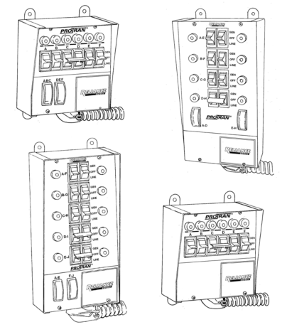
Key Components of the Reliance Transfer Switch
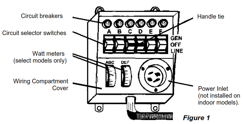
Circuit breakers. Each transfer switch circuit has a 15- or 20-amp push-to-reset circuit breaker that protects the branch circuit when the circuit selector is in the GEN position. In the LINE position, each branch circuit is protected by the breaker in the load center.
Circuit selector switches. These switches allow you to select either GEN (generator) or LINE (utility) as the power source for the branch circuits that have been wired through the transfer switch. The OFF position is generally not used, as a switch in the OFF position removes that branch circuit from both utility and generator power.
Handle ties. Handle ties are used for 240-volt circuits. They may be removed for 120-volt circuits. See page 6 for instructions on removing and adding handle ties.
Power inlet (cord-connected models only). The power cord from the generator is plugged into this inlet. This is supplied separately for indoor models to encourage the use of a remote connection outdoors reducing the likelihood of running the generator indoors which is extremely dangerous (see page 7 for installation instructions). If this indoor model is installed outdoors, make sure it is protected from the outdoor elements.
Power inlet filler plate. Models without the power inlet installed have a filler plate covering the hole in the wiring compartment cover (models shown on cover). This can be replaced with a power inlet (see Power inlet above).
Wiring Compartment Cover. All models include a wiring compartment that can be used to hard-wire the unit to a remote power inlet box.
Watt meters (select models only). These meters indicate the total load, in watts, on each side of the generator when the generator is supplying power as follows:
| The left meter measures the load on | |
| A, B and C | 6-circuit |
| A, B, C, and D | 8-circuit |
| A, B, C, D and E | 10-circuit |
| The right meter measures the load on | |
| D, E and F | 6-circuit |
| E, F, G and H | 8-circuit |
| F, G, H, I and J | 10-circuit |
Note: The wattmeters will register only if power is being used from the generator.
Installation Instructions
Preparing for Installation
You will need the following items:
Electric drillScrewdriverWire cutters/stripperHammerFour anchors and screws4, 6, 8 or 10 yellow wire connectors (depending on the model)4 red wire connectors for the 20A and 30A hard-wire models4 blue wire connectors for the 50A hard-wire models
The following five steps generally apply to all transfer switch installations. For flush-mounted units (model number begins with the letter “F”), please see the supplemental installation instructions packaged with each unit, as they will supersede some of the instructions shown here. For outdoor units (model number begins with the letter “R”), connect the wires from the unit to the main panel per these installation instructions. Please note the special conduit for the outdoor unit is included but not installed on the unit. Install the conduit supplied using acceptable practices for a raintight application.
The transfer switch may be installed on either side of the load center.
- Turn off the main circuit breaker in the load center to ensure your safety.Danger: All current-carrying parts on the LINE side of the main are still live
- Remove the cover of the load center.
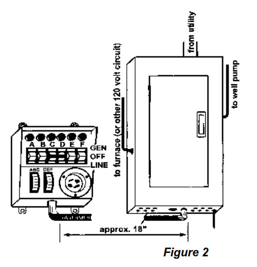
- Locate and remove a knockout (ko) in the bottom of the load center (Figure 2). Use a 1/2″ ko for 4-circuit models, a 3/4″ ko for 6-circuit models, and a l” ko for 8-to 10-circuit models.
- Insert the wires extending from the end of the flexible conduit through the ko. Attach the conduit connector securely with the locknut provided.
- Anchor the transfer switch to the wall using the external feet. Do not attempt to bend the flexible conduit beyond its structural capabilities.
Wiring the Reliance Transfer Switch to the Load Center
Determine which circuits will be used during an emergency. See the residential wattage requirement chart on the inside front cover of this manual. If a selected circuit is part of a multi-wire branch circuit, ensure the other branch circuit that shares the neutral is also connected to the transfer switch. The two circuits must be connected to opposing legs (phases) of the generator power and a handle tie must be installed on the switch handles so that both legs are transferred at the same time.
![]() Warning: Failure to properly install a multi-wire branch circuit could result in overloading the neutral wire.
Warning: Failure to properly install a multi-wire branch circuit could result in overloading the neutral wire.
The maximum number of circuits available and those that can be used for multi-wire branch circuits depends on the model of the transfer switch as follows:
|
Model |
Max |
Available for multi-wire branch circuits |
|
15114A, 30114A |
4 |
None |
|
31404A, B or C, 20504B, 30504B |
4 |
Circuits B and C. |
|
All 6-Circuit Models
|
6
|
Circuits C and D only on indoor models. Any two adjacent circuits on outdoor models (models with an “R” prefix). |
|
All 8-Circuit Models |
8 |
Any two adjacent circuits. |
|
All 10-Circuit Models |
10 |
Any two adjacent circuits. |
Balancing the Load

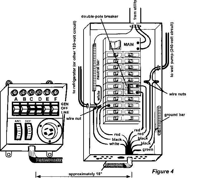
To maximize the efficiency of your generator, divide appliance circuits and others requiring higher wattage between the left and right side of the transfer switch so that a usage balance is achieved.For example, on a 6-circuit transfer switch, consider wiring the refrigerator to Switch A and the furnace to Switch D (Figure 3).
Installing 120-volt Circuits
![]() Warning: Transfer switch circuits with 20 amp breakers (the ones with the red caps) must be installed on only those branch circuits with 20 amp branch circuit breakers. Transfer switch circuits with 15 amp breakers can be installed on 15 or 20 amp branch circuits. Do not install any transfer switch circuit on branch circuits greater than 20 amps.Wire the most critical circuits first, starting with Switch A on the transfer switch. Let’s assume that Switch A will be designated to supply power to the refrigerator.
Warning: Transfer switch circuits with 20 amp breakers (the ones with the red caps) must be installed on only those branch circuits with 20 amp branch circuit breakers. Transfer switch circuits with 15 amp breakers can be installed on 15 or 20 amp branch circuits. Do not install any transfer switch circuit on branch circuits greater than 20 amps.Wire the most critical circuits first, starting with Switch A on the transfer switch. Let’s assume that Switch A will be designated to supply power to the refrigerator.
- Turn off the refrigerator circuit breaker. Loosen the screw that secures the wire to the circuit breaker. Disconnect the wire from the circuit breaker.
- On the transfer switch, find the black and red wires marked A.
- Feed the red wire to the selected breaker, in this case the refrigerator breaker.
- Cut the red wire A to a convenient length. Strip approximately 5/8″ from the end of the wire. Connect the red wire to the refrigerator circuit breaker and retighten the screw.
- Cut the black wire A to a convenient length for aligning with the wire removed from the refrigerator circuit breaker in step 1. Strip approximately 5/8″ from the end of the wire.
- Insert both wires (the wire removed from the circuit breaker in step 1 and the black wire) into a yellow wire connector. Twist the connector tightly and push the wires back into the wiring compartment of the load center.
This completes the installation of the transfer switch for your refrigerator.
Repeat steps 1-6 for each of the remaining considering the following:
- See the following section for 240-volt circuits and the removal of handle ties if 240-volt circuits are not required.
- Remember to “balance the load”—dividing the appliances requiring higher wattage between the left and right sides of the transfer switch.
- If you are installing model 15114A or 30114A, follow the same steps for B, C and D circuits, and proceed to the instructions for completing the installation on page 8.
Installing 240-volt Circuits
On certain models, two adjacent circuit selector switches may be used for 240-volt operation. A handle tie is used to connect the two circuit selector switches for the following circuits:
|
Models 15114A, 30114A |
None (these are for 120-volt use only) |
|
Models 31404A, B or C, 20504B, 30504B |
Circuits B and C. |
|
All 6-Circuit Models
|
Circuits C and D only on indoor and flush models. Any two adjacent circuits on outdoor models (Models with an “R” prefix)*. |
|
All 8-Circuit Models |
Any two adjacent circuits* |
|
All 10-Circuit Models |
Any two adjacent circuits* |
*Note: Circuits used for multi-wire branch circuits are not available for 240-volt circuits
Removing handle ties. If there are no 240-volt or multi-wire circuits in the transfer switch installation, handle-ties on the switches are not needed. To remove a handle tie, place the handle-tied switch in the GEN position. Loosen the two screws and remove the handle tie.
Adding handle ties. If additional ties are needed to accommodate additional 240-volt or multi-wire circuits, they can be added to adjacent pairs of switches according to the table above.
![]() Warning: Transfer switch circuits with 20 amp breakers (the ones with the red caps) must be installed on only those branch circuits with 20 amp branch circuit breakers. Transfer switch circuits with 15 amp breakers can be installed on 15 or 20 amp branch circuits. Do not install any transfer switch circuit on branch circuits greater than 20 amps.
Warning: Transfer switch circuits with 20 amp breakers (the ones with the red caps) must be installed on only those branch circuits with 20 amp branch circuit breakers. Transfer switch circuits with 15 amp breakers can be installed on 15 or 20 amp branch circuits. Do not install any transfer switch circuit on branch circuits greater than 20 amps.
Installing 240-volt circuit(s)
- Locate the two red and two black wires for the circuits with the handle tie.
- Turn off the double-pole breaker in the load center.
- Loosen the screws that secure each wire to each circuit breaker. Disconnect the wires from the circuit breakers.
- Feed the two red wires from the handle-tied switch(es) to the double-pole circuit breaker.
- Cut the red wires to a convenient length. Strip 5/8″ from the end of each wire. Connect the two red wires to the double-pole circuit breaker.
- Cut the black wires to a length convenient for aligning with wires removed from the circuit breaker. Strip 5/8″ from the end of each wire.
- Insert one wire removed from the circuit breaker and one black wire into a yellow wire connector. Twist to tighten and push the wires back into the wiring compartment of the load center. Do the same for the other wire removed from the circuit breaker and the other black wire from the transfer switch.
Repeat steps 1-7 for the other double-pole circuits (8- and 10-circuit models only). For Indoor Surface Mount Models (those with no power inlet) or to hard-wire cord-connected Models (those with a suffix “A” in the Model number), continue to the next section entitled “Hard-wire Installation” to complete the installation.
For all other models, skip to “Completing the installation” on page 8.
Hard-wire Installation 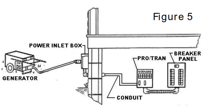
“Hard-wire” installation to a power inlet box located remotely from the transfer switch (Figure 5) requires additional steps to complete the installation. The wire connections to the wires from the power inlet box are made in the wiring compartment of the transfer switch. Access the wiring compartment by removing the wiring compartment cover (See Figure 1). This done by removing the two screws located at the bottom of the front of the transfer switch. Replace the cover when installation is complete.
Watt Meters. Some Models are supplied with watt meters to measure the generator output. When connecting the transfer switch to either a power inlet or power inlet box, run the black wire lead going to the inlet through the hole in the current transformer (the small black doughnut-shaped device) attached to the left-hand meter before connecting it to the power inlet or the wires from the power inlet box. Run the red wire lead through the hole in the current transformer attached to the right-hand meter before connecting it to the power inlet or the wires from the power inlet box. No direct connection to the meter is necessary for the meters to function as described on the bottom of page 2.
Hard-wire Models. All of these Models have leads in the transfer switch wiring compartment that needs to be connected to the incoming wires from the remote power inlet box. See Watt Meters above for Models ending with a suffix “C”. Connect the wire leads in the transfer switch to the remote power inlet box using the following color key:
- the black wire to the power inlet X or Y terminal.
- the white wire to the power inlet neutral W terminal. ③ the red wire to the power inlet X or Y terminal.
- the green wire to the power inlet ground G terminal.
The incoming power from the generator may be supplied to any of the above models through the optional power inlet. This optional inlet enables a cord connects directly to the front of the transfer switch. Simply remove the plastic cover plate with the Reliance name embossed on it, install the appropriately sized power inlet and wire according to the inlet instructions using the same color key as used for the remote power inlet box.
Inlet Installation
Suffix A models have a power inlet included. The inlet can be installed on the unit by removing the wiring compartment cover (described in the proceeding section) and the power inlet cover plate, installing the inlet with the enclosed screws onto the wiring compartment cover, and connecting the wire leads to the inlet as described in the instructions included with the inlet. See Watt Meters above before making the connections. Make sure the transfer switch is protected from the outdoor elements when installed outdoors.
Completing the Installation
When you have wired all the load circuits in the transfer switch, only the white neutral wire and the green ground wire remain.
- Insert the white neutral wire into an unused opening in the neutral bar in the load center and tighten the screw (Figure 4).
- Insert the green ground wire into an unused opening in the ground bar, if existing, and tighten the screw. If no ground bar exists, insert the green wire into an unused hole in the neutral bar and tighten the screw.
- Replace the cover to the load center.
- Fill in the chart on the transfer switch to identify your emergency circuits and corresponding circuit numbers in the load center.
- Turn on all branch circuit breakers and the main breaker that were turned off for installation in the load center.
- Turn all switches on the transfer switch to the LINE position. Installation is now complete.
Operating Instructions
Using your Reliance Transfer Switch and Your Portable Generator
![]() Warning: Do not operate a generator in an enclosed area. Do not operate a generator where the exhaust fumes can accumulate in an enclosed area.
Warning: Do not operate a generator in an enclosed area. Do not operate a generator where the exhaust fumes can accumulate in an enclosed area.
You want your generator to be ready when you need it. Therefore, it is important to perform the following steps at least once a month to keep the generator in peak running condition.
- Start and run your generator under load regularly.
- Keep the fuel tank filled with fresh fuel.
It is not necessary to turn off any circuits in the load center when supplying generator power with the transfer switch, even when the utility power is operating normally. The double-throw action of these switches prevents feeding generator power to the utility and, conversely, prevents feeding utility power to the generator.
Transferring from Utility Power to Generator Power
- Plug the female connector of the generator power cord into the power inlet box or the power inlet on the transfer switch. All circuit selector switches on the transfer switch should be in the LINE or OFF position.
- Insert the male plug of the power cord into the outlet on the generator.
- Start the generator outdoors. Follow the procedures described in the generator owner’s manual furnished by the manufacturer of the generator.
- Select the circuits to be powered by the generator by moving the corresponding switches on the transfer switch to the GEN position. Use only necessary household items when under generator power.
- Alternate use of larger loads (furnace motors, well pumps, refrigerators, etc.) to balance the load. See “Balancing the load” on page 4. Do not exceed the maximum wattage of the transfer switch.
- Some circuits are limited by the transfer switch circuit breaker to a maximum of 15 amps when switched to the GEN position. If you have switched on a circuit selector switch on such a 15-amp circuit to the GEN position that normally draws more than 15 amps, turn off some of the appliances on that circuit to avoid exceeding the 15-amp load for that circuit.
- Test your circuits by using the watt meters on the transfer switch or determine wattage from the nameplate on each appliance or motor.
- Models 15114A, 30114A, and all suffix “B” Models except the 8-circuit Models do not have watt meters. See the note below for additional information on these models.
- Make a note of any excessive loads. These loads must be turned off during generator operation.
Transferring from Generator Power to Utility Power
- Return all circuit selector switches to the LINE position.
- Follow the procedures in the generator owner’s manual to turn off the generator.
- Unplug the power cord.
Notes on Models Without Watt Meters
If there are no watt meters for checking appliance or motor load, check the nameplate on each appliance or motor and note the load for each.
The total running wattage for each of these models is as follows:
|
Model 15114A |
1875 watts |
|
Model 30114A |
3750 watts |
|
30A Models (see Maximum Input on cabinet label) |
7500 watts |
|
50A Models (see Maximum Input on cabinet label) |
12500 watts |
During an emergency, the switches should be in the OFF or LINE position when a particular load is not needed. Failure to limit the total load to the total running wattage may cause the generator to stall or burn out the appliance motor.
Specifications and Parts List
|
Specifications and Parts List |
|||||||||
|
Model # / Configuration |
15114A
|
30114A
|
20A 6-Cir |
30A 6-Cir |
50A 6-Cir |
30A 8-Cir |
50A 8-Cir |
30A 10-Cir |
50A 10-Cir |
|
Max. Watts |
1875 |
3750 |
5000 |
7500 |
12500 |
7500 |
12500 |
7500 |
12500 |
|
Max. single-pole circuits |
4 |
6 |
8 |
1 0 |
|||||
|
Max. double-pole and multi-wire circuits |
0 |
1 |
4 |
5 |
|||||
|
# of handle ties provide d |
n/a |
1 |
2 |
||||||
|
Max. combined loads Amps @ 125 VAC |
15 |
30 |
40 |
60 |
100 |
60 |
100 |
60 |
100 |
|
Max. combined loads Amps @ 250VAC |
n /a |
20 |
30 |
50 |
30 |
50 |
30 |
50 |
|
|
Max. load/circuit from generator |
15 amps |
4-15 a mps & 2-20 amps |
6-15 a mps & 220 amps |
6-15 a mps & 420 amps |
|||||
|
Max. load/circuit from load center |
20 amps |
||||||||
|
Power inlet, NEMA* |
|||||||||
|
configuration – Cord Connected Models |
5-15 |
L5-30 |
L14-20 |
L14-30 |
CS6365 |
L14-30 |
CS6365 |
L14-30 |
CS6365 |
|
Minimum cord gauge |
14 |
10 |
12 |
10 |
6 |
10 |
6 |
10 |
6 |
|
No. of conductors (wires) |
3wire |
4-wire |
|||||||
|
Conduit length |
18″ |
||||||||
|
Conduit, trade-size diameter |
1 /2″ |
3/4″ |
1 “ |
||||||
|
Optional Power Inlet Catalog # |
PB15 |
PB31 |
PB20 |
PB30 |
PB50 |
PB30 |
PB50 |
PB30 |
PB50 |
|
Shipping weight |
9 lbs. |
10 lbs. |
13 lbs. |
||||||
|
Dimensions (H x W x D |
) 7 1/2″ x 7″ x 4 1/2″ |
13 1/4″x 7″x 4″ |
*National Electrical Manufacturer’s Association
Note: If your model is not listed here, please refer to the supplemental installation instructions packaged with that unit.
Transfer Switch Parts List
|
Description |
Part# |
|
Circuit breaker, 15A |
6291 |
|
Circuit breaker, 20A |
6292 |
|
Wattmeter, 30A (3750 watts) |
6293 |
|
Current Transformer (3750 |
6294 |
|
Switch, 30A SPDT |
7801 |
|
Power inlet, 20A |
6503 |
|
Power inlet, 30A |
6702 |
|
Handle tie |
6295 |
|
Power Inlet Filler Panel |
6271 |
Optional Accessories
Power Inlet Boxes 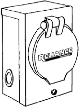
Ideal for installations where the house electrical panel is located indoors. No need to run the power cord from the generator to the transfer switch through a door or window. This weather-tight power inlet box can be mounted on the exterior of the house. Run wiring through the wall from the inlet box to the transfer switch installation inside. The generator power cord may then be plugged into the power inlet box.
|
Catalog# |
Connector configuration |
Inlet description |
For use with models |
|
PB15 |
5-15 |
3-wire weather-tight male |
15114A |
|
PB20 |
L14-20 |
4-wire weather-tight male |
20216A |
|
PB30 |
L14-30 |
4-wire weather-tight male |
All 30A Models
|
|
PB31 |
L5-30 |
3-wire weather-tight male |
30114A |
|
PB50 |
CS6364 |
4-wire weather-tight male |
All 50A Models |
Flush Kits 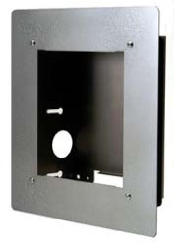
Kits for flush mounting all Pro/Tran® indoor transfer switches are available. Order KF6 for the four- and six circuit models and KF10 for the eight- and ten-circuitmodels.
Hinged Covers
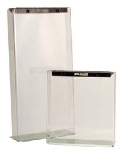
High-impact clear plastic covers protect from accidental contact with a transfer switch. Order CK6 for the four- and six-circuit models and CK10 for the eight- and tencircuit models.
Power Cords 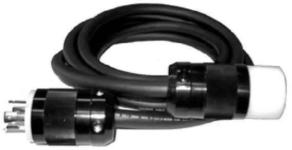
These heavy duty cord sets are the connecting link between the generator and the Reliance transfer switch or the power inlet box. The 4-wire locking plug and connector match up with the power inlet on each Reliance transfer switch and with the inlet on the power inlet box. Most portable generators suitable for 120/240 full-power operation are supplied with either a 20-amp or 30-amp, 4-wire locking receptacle that accepts the locking plug and connector on each end of the cord set.
Watt Meter Panel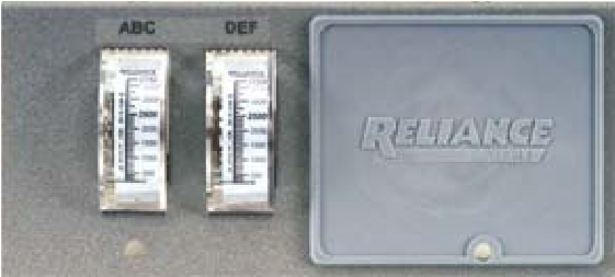
Watt Meter Panel WP7500 may replace the blank cover on any indoor suffix B Pro/Tan® model to provide important information on the output from a 20A or 30A, 125/250VAC generator. Accuracy is plus or minus 3%.
Reliance Controls Corporation is pleased that you have made the decision to purchase this product. We have been manufacturing innovative, quality electrical controls for nearly 100 years. Our products are backed by one of the best warranties in the industry.
Reliance transfer switches are
 Warranty
Each Reliance transfer switch or accessory is guaranteed against mechanical or electrical failure due to manufacturing defects for a period of 24 months following shipment from the factory. The manufacturer’s responsibility during this warranty period is limited to repair or replacement, free of charge, of products proving defective under normal use or service when returned to the factory, transportation charges prepaid. Guarantee is void on products that have been subjected to improper installation, misuse, alteration, abuse or unauthorized repair. The manufacturer makes no warranty with respect to the fitness of any goods for a user’s particular application and assumes no responsibility for proper selection and installation of its products. This warranty is in lieu of all other warranties, expressed or implied, and limits the manufacturer’s liability for damages to the cost of the product. This warranty gives you specific legal rights, and you may have other rights, which vary from state to state.
 Reliance Controls Corporation / 2001 Young Court / Racine, Wl 53404
Phone: (800) 634-6155 Fax: (262) 634-6436
© Copyright 2000 Reliance
RELIANCE ProTran Manual Transfer Switches Installation and Operating Instruction – RELIANCE ProTran Manual Transfer Switches Installation and Operating Instruction –
[xyz-ips snippet=”download-snippet”]