48V030-GC2 MANUAL
1. INTRODUCTION
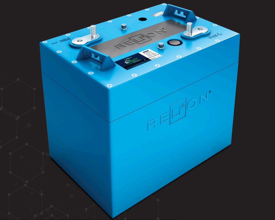
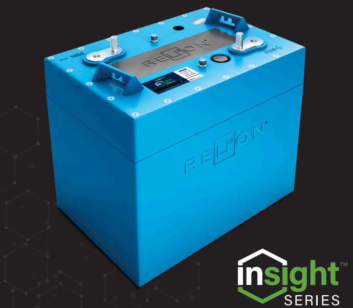
RELiON’s InSight Series batteries are the first scalable LiFePO4 drop-in replacement battery, that comes in an industry standard, GC2 size.
2. SCOPE
This document applies to model 48V030-GC2.
3. ABBREVIATIONS
- State of Charge (SOC)
- State of Health (SOH)
- Over Voltage Protection (OVP)
- Under Voltage Protection (UVP)
- Over Temperature Protection (OTP)
- Under Temperature Protection (UTP)
- Over Current Protection (OCP)
- Short Circuit Protection (SCP)
- Light Emitting Diode (LED)
- Pulse Recovery Operation (PRO)
- Controller Area Network bus (CANbus)
- Battery Display Indicator (BDI)
4. PRODUCT SPECIFICATIONS
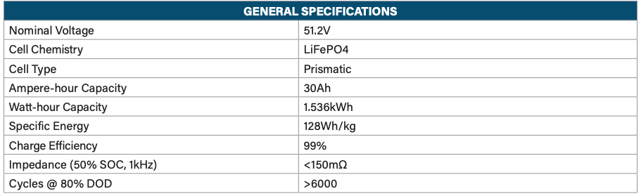
4.1. General Specifications
4.2. Electrical Specifications
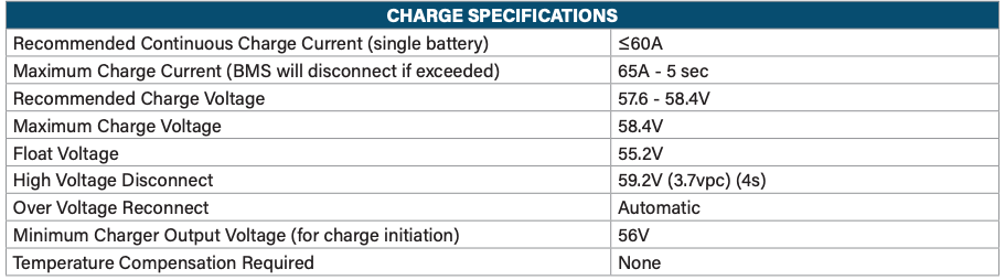
4.2.1. Charging Specifications
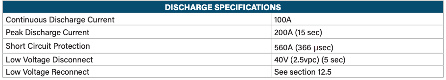
4.2.2. Discharging Specifications
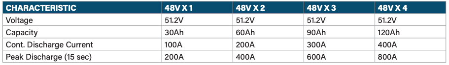
4.2.3. Parallel Specifications
All the currents are additive in Parallel operation. See table below.
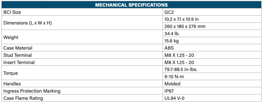
4.3. Mechanical Specifications
4.4. Drawing
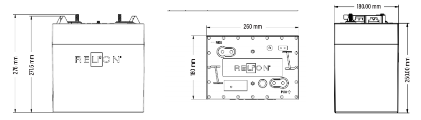
Dimensions shown in mm
5. BATTERY INSTALLATION
To ensure proper operation of the battery (for single-battery or multiple-battery installations), follow the steps below:
- InSight batteries can only be used in parallel (not series). Up to 10 batteries may be connected.
- Select proper wire gauge for your applications electrical current (A) demands (Suggested reference: NEC 2014: Table 310.15(B)(16) Allowable Ampacities of Insulated Conductors).
- On new installations it is recommended that new battery cables (free from corrosion) be used.
- Ensure that all battery cables are equal in length to avoid battery imbalances. CAUTION : Any existing 12V accessories (lights, radio, etc) must be connected to an auxiliary DC/DC converter (48V to 12V)
- All cables should terminate at bus bars with respect to their polarity.
- Torque the battery terminals appropriately as listed in Section 4.3.
- Connect the provided Controller Area Network bus (CANbus) cables as shown in Section 5.1.
- Turn batteries ON. See the table in Section 8 or Section 12.2 for written instructions.
- Charge the batteries to 100% State of Charge (SOC) prior to use.
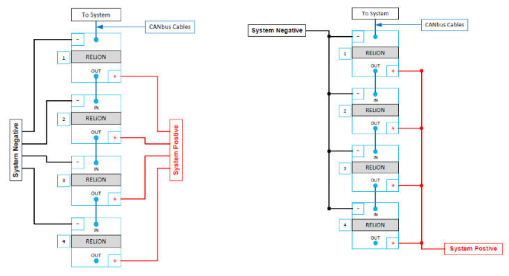
5.1. Parallel Connections – Options 1 and 2
5.2. Battery Orientation
The best way to install the battery is upright as the bottom of the case is flat. The battery can be placed in the following orientations:
- Upright
- Short sides – either side
- Long side – only with positive side up
DO NOT INSTALL the battery on the long side with the negative side up as this can put stress on the internal connections causing damage that may result in battery failure.
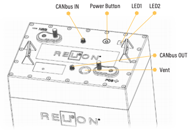
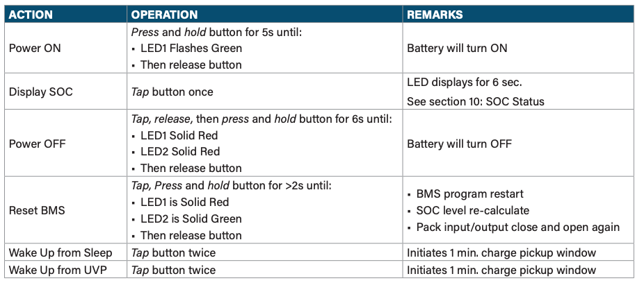
6. BATTERY INTERFACE
The battery has a button located next to the LED display that is used to:
- Turn the battery ON/OFF/RESET
- Request the battery SOC
6.2. LEDs
The battery has two tri-colored LED lights on the cover (green, yellow, and red) that are used to communicate:
- Battery Status
- Battery SOC
- Battery Protection/Error Status
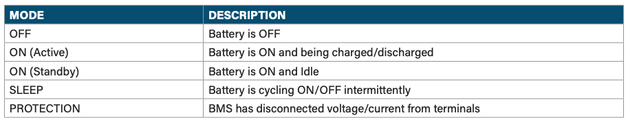
7. BATTERY MODE DESCRIPTIONS
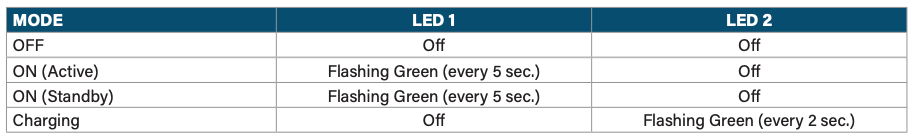
9. LED FUNCTION 1 – BATTERY STATUS
11. LED FUNCTION 3 – PROTECTION/ERROR INDICATORS

12. BATTERY MODE OPERATION DETAILS
12.1. OFF Mode
The battery ships in the OFF mode. There is no LED activity and voltage is not present at the terminals. To turn the battery OFF: Tap the button once, release, then press the button again holding for 6 seconds until you see both LEDs display solid red lights then release the button. This action will turn off both LEDs.
12.2. ON Mode
To turn the battery on press button for 5 seconds. LED1 will flash green every 5 seconds.
- ON (Active) – The battery is in ACTIVE mode only while being charged or discharged.
- ON (Standby) – STANDBY mode is any time the battery is ON and not being discharged or charged. When a battery is in STANDBY mode, voltage is present at the terminals. If it is charged or discharged during STANDBY mode it will return to into ACTIVE mode. If a battery is sitting in STANDBY mode continuously for more than 72 hours if battery voltage ≥48V or 30 hours if battery voltage <48V, it will enter SLEEP mode. The minimum charge current to re-enter active mode is 0.5A (2s) or discharge current is 0.8A (1s).
12.3. SLEEP Mode
The battery will go into SLEEP mode if it is in STANDBY mode for more than 72 hours without being discharged or charged. The LEDs will not be illuminated.
The battery will go into a Pulse Recovery Operation (PRO) while in SLEEP mode.
12.3.1. Pulse Recovery Operation (PRO) During SLEEP Mode
The purpose of Pulse Recovery Operation is to place the battery in a low power state in order to preserve its energy. The battery will cycle between the OFF and ON (Standby) modes as follows:
- The battery will turn ON (Standby) for 1 minute every 10 minutes. LED1 will flash green every 0.5 seconds when the battery is ON for 1 minute.
12.4. UNDER VOLTAGE PROTECTION (UVP) Mode
If the battery voltage reduces to less than 40.0V, or any individual cell reduces to less than 2.5V, the battery will go into UVP protection mode. LED1 will flash RED every five (5) seconds.
The battery will go into a Pulse Recovery Operation (PRO) in UVP mode.
12.4.1. Pulse Recovery Operation (PRO) During UVP
The purpose of Pulse Recovery Operation is to place the battery in a low power state in order to preserve its energy. The battery will cycle between the OFF and ON (Standby) modes as follows:
- Day 1: The battery will turn ON (Standby) for 1 minute every 10 minutes. LED1 will flash green every five (5) seconds for 1 minute then return to flashing red once every five (5) seconds until next interval. (As shown below the OFF interval increases by 10 minutes each day).
- Day 2: The battery will turn ON (Standby) for 1 minute every 20 minutes.
- Day 3 to 24: The duration of the OFF phase will increase by 10 minutes every 24hrs and the duration of the ON phase will remain at 1 minute.
- Day 25: The battery will turn itself OFF indefinitely. The battery must be turned ON as described in Section 12.2.
12.5. Turn Battery ON during PRO
- Connect a compatible battery charger to the battery during any, 1-minute ON (Standby) phase in Pulse Recovery Operation. This will return the battery to ON (Active) mode.
- The 1 minute ON phase can also be triggered manually by tapping the button twice. A compatible battery charger must then be connected before the battery turns OFF.
13. BMS PROTECTION DETAILS
13.1. Under Voltage Protection (UVP)
LED1 – Flash Red (every 5 seconds), LED2 – Of
This mode protects the battery from reaching a low voltage level that can damage the battery. If the battery voltage reduces to less than 40.0V, or any individual cell reduces to less than 2.5V, for five (5) seconds the battery will go into UVP protection mode. The battery will simultaneously be in a PULSE RECOVERY mode as explained above. The methods for recovering the battery from PULSE RECOVERY mode and returning it to ON mode are the same as above. Depending on the cause, the battery may self-recover from UVP if allowed to rest. In the event the battery does not recover, manually initiate recovery as written above. The battery will automatically reconnect when the voltage is ≥46.4V
13.2. Over Voltage Protection (OVP)
LED1 – Flash Green (every 5 seconds), LED2 – Of
This mode protects the battery from reaching a high voltage level that can damage the battery. If the battery voltage increases to greater than 59.2V for four (4) seconds, or any individual cell increases to greater than 3.7V, the battery will go into OVP protection mode. The battery will automatically reconnect if discharged or when the highest cell voltage is <3.4V and the SOC <96%.
13.3. Under Temperature Protection (UTP)
LED1 – Flash Green (1 second), LED2 – Flash Red (1 second)
This mode protects the battery from being charged in temperatures below freezing, which can damage the battery. The BMS will not allow charge current when the battery temperature is below freezing (0°C/-32°F). However, the BMS will allow discharge below freezing down to -30°C/-22°F. The battery will automatically reconnect when the temperature increases again.
13.4. Over Temperature Protection (OTP)
LED1 – Flash Green (every 1 second), LED2 – Flash Red (every 1 second)
This mode protects the battery from reaching high temperatures, which can damage the battery.
- Charge OTP – The BMS will disconnect while charging when the battery temperature exceeds 55°C/131°F.
- Discharge OTP – The BMS will disconnect while discharging when the battery temperature exceeds 65°C/149°F.
13.5. Over Current Protection (OCP)
LED 1 – Solid Green, LED 2 – Solid Yellow
This mode protects the battery from discharging at excessive levels of current. The maximum current level values for banks of up to four (4) batteries are listed in the Discharge Specification in Section 4.2.2. The maximum current levels are additive and must be calculated for banks of more than 4 batteries.
13.6. Short Circuit Protection (SCP)
LED1 – Solid Green, LED2 – Solid Yellow
This mode protects the battery from discharging at extremely high levels of current. The short circuit current level for a single battery is listed in the Discharge Specification in Section 4.2.2.
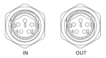
14. CANBUS COMMUNICATION
This section provides the basics for CANbus operation and/or integration. For additional details on how to interface to the CANbus and interpret the messages consult the RELiON CANbus Specification Document. Parallel connected InSight batteries communicate internally via CANbus. External communication is available through the CANbus OUT port of the battery.
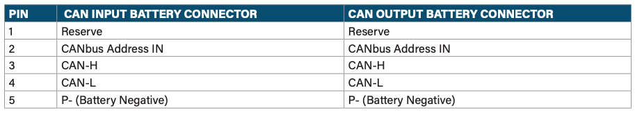
14.1. CAN Battery Connectors: M8-5P
14.2. Communication Hardware
The batteries do not have 120Ω termination resistors. Up to ten batteries may be read in a single CANbus network.
14.3. CANbus Details
- CAN2.0A
- Identifier: 11-bit
- Broadcast ID: 0x5FF
- Bit Rate: 250kbps
- Multi-Byte value form: Little-Endian
14.4. Broadcast Data
The BMS broadcasts alarms, system status, and SOC every 3 seconds via ID 0x5FF. If an alarm is triggered it will be broadcasted immediately.
14.5. Broadcast Data Frame

15. CHARGING GUIDELINES
Follow these charging guidelines to achieve optimal performance and maximum life from your RELiON Lithium Iron Phosphate (LiFePO4) InSight battery.
Conventional 48V lead acid chargers can be connected to the InSight battery without concern/harm as the battery BMS will protect the battery against improper charge conditions (this will not void the warranty). Please read and exercise the charging practices below to achieve the best results.
15.1. Charger Inspection
Check that your charger’s cables are insulated and free of breakage. Charger terminal connectors should be clean and properly mate with the battery terminals to ensure a good connection and optimum conductivity.
15.2. Charge Temperature
LiFePO4 batteries can be safely charged between 0°C to 55°C (-4°F to 131°F).
LiFePO4 batteries do not require temperature compensation for voltage when charging at hot or cold temperatures.
The InSight Series batteries come with a BMS that protects the battery from over-temperature. If the BMS disconnects due to high temperature, wait until the temperature reduces before using or charging the battery. Please refer to your specific battery’s Data Sheet for the BMS high temperature cut-off and reconnect values.
15.3. Prior to Charge
- It is best to use/select a Lithium, GEL or AGM charge profile in that order of availability. Consult your manual or charger manufacturer for directions on this capability. Some charger models only have the stock charge profile available.
- Please wait 2 minutes after using the battery to plug in the charger. This allows the battery to properly accept charge current and disengage the regen circuit.
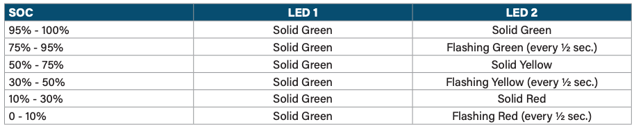
- Spot check the battery SOC LED indicators with a quick press and release of the battery Power Button. See the table in Section 10 to determine the SOC.
15.4. During Charge
- Check if charge current is being supplied in one of the following ways:
- Battery LED indicators: The proper LED sequence be displayed: LED1 – Off, LED2 – flashing green (every 2 seconds).
- RELiON Battery Display Indicator (BDI): Spot check the accessory gauge to see if charge current is flowing and battery SOC percentage increasing
- Digital Voltmeter w/amp clamp (DVM): Spot check the accessory gauge to see if charge current is properly flowing.
15.5. Charge Completion
- The Charger’s behavior at the end of a Lithium battery recharge may vary from the standard operation consistent with charging lead-acid batteries.
- Chargers typically display a solid Green Light when the charge is completed, and a flashing green light when the battery is near the end of charge (will vary by charger). Both conditions may or may not occur depending on your charger design. Neither condition is necessarily required to properly achieve a full recharge.
- Lithium batteries may temporarily disconnect their voltage as they reach a full charge, before the charger is complete. This may cause the charger to repeat its charge initiation sequence when this occurs (various lights and noises may occur during this sequence). This is acceptable and will not harm the battery. Simply unplug or disconnect the charger, if this occurs, and the battery voltage will return.
- Check to see if a full charge was completed in one of the following ways:
- Battery LED indicators: Spot check the battery LED’s with a quick press and release of the battery Power Button. See the table in Section 10 to determine the SOC.
- RELiON Battery Display Indicator (BDI): Spot check the accessory gauge to see if battery SOC percentage reached 100%.
15.6. Charge Parameters
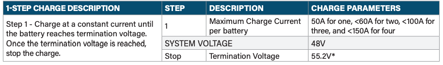
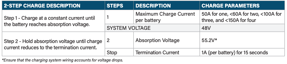
LiFePO4 batteries can be charged with either a 1-stage profile (constant current (CC) aka Bulk Stage) or a 2-stage profile (constant current, constant voltage (CC-CV) profile aka Bulk and Absorption Stages). The 1-stage profile will charge the battery ~97% and the 2-stage profile will charge the battery 100%. The 1-stage profile is sufficient, since LiFePO4 batteries do not need to be fully charged; this will not reduce life as it does with lead-acid batteries.
15.6.1. CC Charge Profile – 1 Stage
16. BATTERY INDICATOR:
If you are using a voltage-based fuel gauge that is designed for lead-acid batteries it will not accurately provide state of charge (SOC). Please replace your fuel gauge with one that measures current rather than voltage. The BMS in the battery provides the SOC of the battery via CAN. Refer to the RELiON Battery CANbus Specification Document for details.
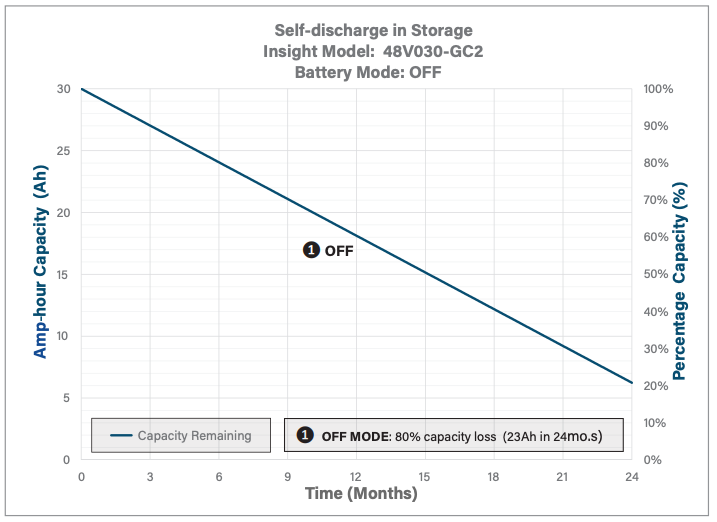
17. BATTERY STORAGE:
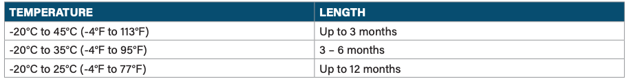
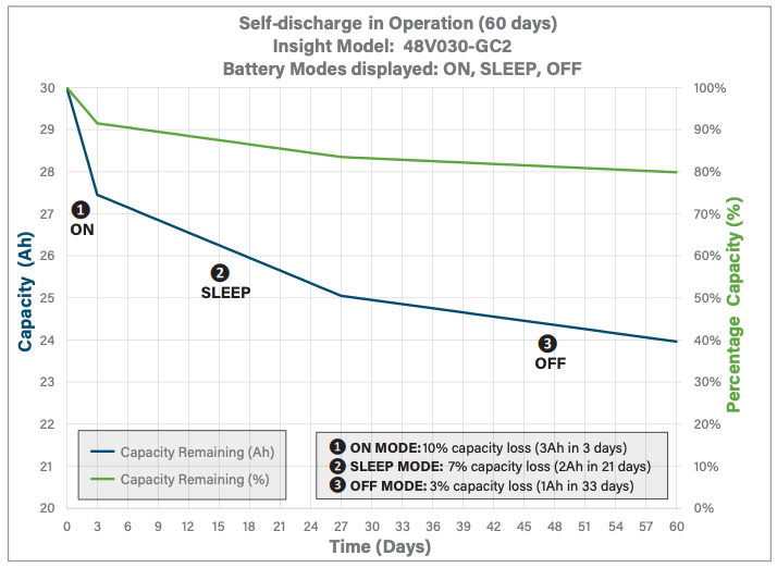
18. ENERGY CONSUMPTION DURING STORAGE:
Important notes about battery self-discharge:
- Golf cars consume power when idle (even in tow mode)
- The battery BMS uses battery power when idle
- Charge the batteries whenever used to maintain full vehicle range.
- The batteries will turn off after 3 days when idle to prevent substantial discharge
- Pressing the Power button for 5sec will wake them up
19. RECYCLING:
Terminals must be covered with a protective cap or non-conductive tape prior to battery disposal to lithium recycler. Dispose of LiFePO4 batteries at an authorized lithium recycling facility.
20. PRECAUTIONS:
Lithium Iron Phosphate (LiFePO4) batteries are an inherently safe chemistry. Please reference RELiON’s Lithium Iron Phosphate Safety Document (available on our website at relionbattery.com) for more details. However, as with any electronics, safety measures should always be taken. Please adhere to the instructions within this manual for safe handling and operation.
- Always wear protective gear when handling batteries
- Use a wrench with a rubber coated handle
- Do not place any objects on top of batteries
- Do not place batteries on a metallic surface
- Check that all cables are in good condition
- Make sure all cable connections are properly tightened
- Install and remove batteries using lifting strap brackets
- Do not smoke near batteries
- Keep sparks, flames and metal objects away from batteries
- Have RELiON’s LiFePO4 Safety Data Sheet (SDS) on premises
- Have a Class ABC fire extinguisher on the premises
If you have any technical questions, please contact RELiON Technical Support at 803-547-7288.
RELiON’s InSight Series Batteries 48V030-GC2 User Manual – RELiON’s InSight Series Batteries 48V030-GC2 User Manual –
[xyz-ips snippet=”download-snippet”]