
REMCO Workhorse Sprayers User Manual
a Division of Green Leaf, Inc®

*These sprayers are designed to be attached to a stable surface.
Assembly / Operation Instructions / Parts
40/60 GALLON UTV SPRAYER
MODELS # UTV425HM, UTV45BLHM, UTV627HM, UTV65BLHM
40/60 GALLON UTV SPRAYER
- Polyethylene Tank
- 12 Volt Diaphragm Pump
- 2.2 or 5.0 G.P.M.
- Lever Handgun
- 25 Ft. of 3/8″ Hose
- Pressure Gauge
- Adjustable Pressure Range
GENERAL INFORMATION
The purpose of this manual is to assist you in assembling, operating and maintaining your lawn and garden sprayer. Please read it carefully as it furnishes information which will help you achieve years of dependable trouble-free operation.
WARRANTY / PARTS / SERVICE
Workhorse products are warranted for one year from the date of purchase against manufacture or workmanship defects for personal or homeowner usage with proof of purchase. Workhorse products are warranted for 90 days for commercial users. Any unauthorized modification of a Workhorse brand sprayer will void warranty.
Your authorized dealer is the best source of replacement parts & service. To obtain prompt, efficient service, always remember to give the following information:
- Correct part description and part number.
- Model number of your sprayer.
Part description and part numbers can be obtained from the illustrated parts list section of this manual.
Whenever you need parts or repair service, contact your distributor/ dealer first. For warranty work always take your original sales slip, or other evidence of purchase date, to your distributor / dealer.
ASSEMBLY INSTRUCTIONS
Tools required:
- 1 — 1/2” Socket Wrench
- 1 — Thread Sealant
OPERATION
The pumping system draws solution from the tank, through the strainer and to the pump. The pump forces the solution under pressure to the spray wand.
The pump has a pressure switch which will shut the pump off when it reaches 60 PSI/2.2 GPM or 45PSI/5.0 GPM
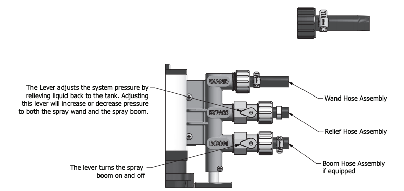
Pressure may be regulated by opening or closing the bypass valve located on the top of the tank. The more it is opened, the lower the pressure will be.
Regularly inspect the suction supply screen on the inside of the tank. Flush with water to clear any accumulated debris.
AFTER SPRAYING
After use fill the sprayer part way with water. Start the sprayer and allow clear water to be pumped through the plumbing system and out through the spray wand.
Refill the tank about half full with plain water and use a chemical neutralizer such as Nutra-Sol® or equivalent and repeat cleaning instructions. Flush the entire sprayer with the neutralizing agent. Follow the chemical manufacturer’s disposal instructions of all wash or rinsing water.
WINTER STORAGE
Drain all water and chemical out of sprayer, paying special attention to pump and valves. These items are especially prone to damage from chemicals and freezing weather.
The sprayer should be winterized before storage by pumping a solution of RV antifreeze through the entire plumbing. Proper care and maintenance will prolong the life of the sprayer.
![]()
WARNING: This product can expose you to chemicals including lead, which is known to the State of California to cause cancer. www.P65Warnings.ca.gov
WARNING: Some chemicals will damage the pump valves if allowed to soak untreated for a long period of time. Always flush the pump with water after use. Do not allow chemicals to sit in pump for extended times of idleness. Follow chemical manufacturers instructions on disposal of all waste water from the sprayer.
Tank Parts List

| ITEM | QTY | PART NUMBER | DESCRIPTION |
| 1 | 1 | 600240 | 40 Gallon Tank* |
| 2 | 1 | 640000 | 60 Gallon Tank* |
| 3 | 1 | 600133 | Tank Lid |
| 4 | 1 | 600134 | Tank Lid Tether |
| 5 | 2 | 600298 | Drain Cap Assembly |
| 6 | 2 | 640105 | Hose Wrap |
| 7 | 2 | 630014 | 10-24 UNC x 1/2″ Screw |
| 8 | 2 | 640463 | Bottom Bar – Bent |
| 9 | 2 | 640485 | 1×2 Rectangular Cap |
| 10 | 2 | 640464 | Adjusting Clip Slide |
| 11 | 2 | 640465 | Adjusting Clip |
| 12 | 2 | 640482 | Adjusting Knob 5/16-18 Thd. |
| 13 | 4 | 640423 | 5/16-18 UNC x 2 3/4″ Hex Bolt |
| 14 | 4 | 640422 | 5/16″ Wide Washer |
| 15 | 4 | 600172 | 5/16-18 UNC Hex Flange Nut |
| 16 | 1 | 600259 | Deluxe Wand with 25ft Hose |
| 17 | 1 | 600153 | 2.2 gpm Pump Wire Kit* |
| 18 | 1 | 600270 | 5.0 gpm Pump Wire Kit* |
*Dependant On Model Purchased
Pump & Valve Assembly
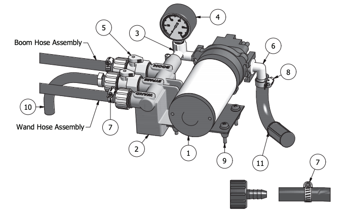
Install Wand Hose Assembly onto Swivel Barb Assembly, by placing a Hose Clamp over the open end of the hose on the Wand Hose Assembly. Then pressing the open end of the hose onto the Swivel Barb Assembly like shown. Secure in place by tightening the Hose Clamp as shown.
| PARTS LIST | |||
| ITEM | QTY | PART NUMBER | DESCRIPTION |
| 1 | 1 | 640451 | 2.2 GPM Pump* |
| 1 | 1 | 630031 | 5.0 GPM Pump* |
| 2 | 1 | 600289 | Manifold Body |
| 3 | 1 | 600291 | Elbow (2.2 pumps) |
| 3 | 1 | 600292 | Elbow ( 5.0 pumps) |
| 4 | 1 | 600129 | Gauge 0-100 PSI |
| 5 | 2 | 600216 | Inline Valve |
| 6 | 1 | 600287 | QD EL 12 |
| 7 | 2 | 600120 | 5/8″ Hose Clamp |
| 8 | 1 | 600288 | 1/2″ Hose Clamp |
| 9 | 4 | 600130 | 10-24 x 1.25 Screw |
| 10 | 1 | 600213 | Relief Hose Assembly |
| 11 | 1 | 600315 | Suction Hose Assembly |
*Pump included depends upon model purchased.
REMCO PROFLO PROFESSIONAL GRADE PUMPS
12 Volt DC Motor-Driven Diaphragm Pumps
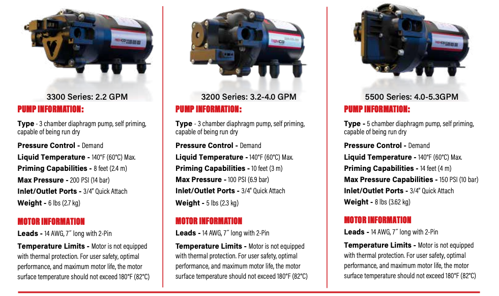
Installation and Operation Precautions
- The pump is equipped with a pressure sensing demand switch that controls the maximum operating pressure.
- In addition, never subject the pump to pressures above factory set/max pressure rating.
- As long as there is inlet water pressure, the pump will not stop forward flow of water even if the motor is turned off. Be sure the system has positive means of shutting off water supply.
- Do not operate pump in an explosive environment. Arcing from the motor brushes, switch or excessive heat from an improperly cycled motor may cause an explosion.
- Do not locate the pump motor near low temperature plastics or combustible material. The surface temperature of the motor may exceed 180°F (82°C).
- Do not pump gasoline or other flammable liquids. Pump head materials are designed for use with water only. Do not use with petroleum products.
- Do not assume fluid compatibility. If the fluid is improperly matched to the pumps’ elastomers, a leak may occur.
- To prevent electrical shock, disconnect power before initiating any work. In the case of pump failure, the motor housing and/or pump fluid may carry high voltage to components normally considered safe. Therefore, always consider electrical shock hazard when working with and handling electrical equipment. If uncertain, consult an electrician. Electrical wiring should only be done by a qualified electrician per local and state electrical codes.
Servicing
- Every Year: Check system against operating standards. Flush with clean water and store in warm dry place.
- Every 2-3 Years: We recommend replacing the valves and checking against operating standards.
Recommendations
Electrical:
- The ProFlo™ series pumps are designed for intermittent duty. Make sure that “OFF” periods are sufficient. Consult the factory for particular data and design criteria.
- Be sure power supply used is adequate for the application.
- Pump and motor specifictions are based on an alternator charged battery (13.6 VDC)
- Use sufficient battery supply power. UTV and lawn tractor batteries may affect pump performance due to low voltage and amp ratings
- Rapid On/Off Cycling must be limited to no more than 6 times per minute, even if the pump is operating in the Continuous Duty zone. Cycling could cause the motor to heat beyond the recommended maximum temperature, and reduce the operational life of the pump and pressure-sensing switch.
Important return safety instructions
When returning your pump for warranty or repair, you must always do the following:
- Contact factory for RMA number.
- Flush chemical residue from the pump (best done in the field).
- Tag pump with type of chemicals having been sprayed.
- Include complete description of operation problem, such as how pump was used, symptoms of malfunction, etc. Since pumps can contain residues of toxic chemicals these steps are necessary to protect all the people who handle return shipments, and to help pinpoint the reason for the breakdown.
References
[xyz-ips snippet=”download-snippet”]