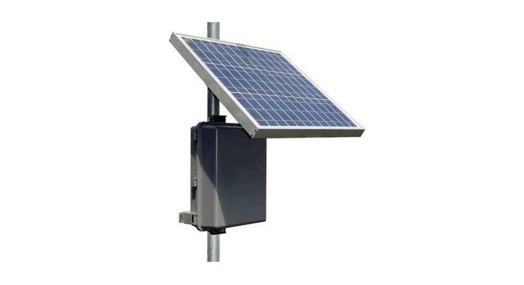
![]() RPPLRemotePro® Remote Power System
RPPLRemotePro® Remote Power System
- Wireless Base Stations and Client Devices
- Surveillance Cameras
- Remote Sensors
- Remote Lighting
- Off-Grid Electronics
 Congratulations! on your purchase of the RemotePro® off-grid remote power system. Please take a moment to review this Qwik Install Guide before assembly or battery installation.
 DANGER! Avoid Powerlines!You Can Be Killed!When following the instructions in this guide take extreme care to avoid contact with overhead power lines, lights, and power circuits. Contact with power lines, lights, or power circuits may be fatal. We recommend installing no closer than 20 feet to any power lines.Safety: For your own protection, follow these safety rules.
- Perform as many functions as possible on the ground
- Do not attempt to install on a rainy, windy, or snowy day or if there is ice or snow accumulation at the install site or if the site is wet.
- Make sure there are no people, pets, etc. below when you are working on a roof or ladder.
 Recommended Tools: Phillips Screwdriver, 1/2″ Open End Wrench, 5/16″ nut driver, Flat Blade Screwdriver
 Recommended Tools: Phillips Screwdriver, 1/2″ Open End Wrench, 5/16″ nut driver, Flat Blade Screwdriver
![]() Please help preserve the environment and return used batteries to an authorized depot
Please help preserve the environment and return used batteries to an authorized depot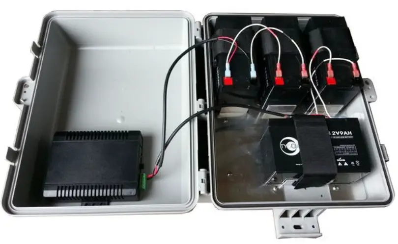
Qwik Install
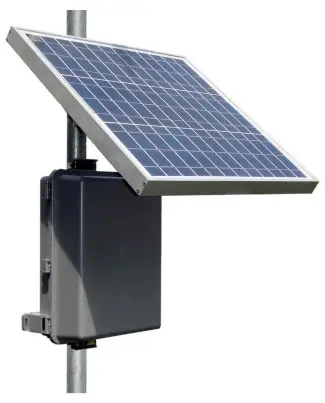
STEP 1: Connect included solar panel cable to the solar panel inside the wire junction box or to the solar panel MC-4 connectors (if applicable). Install solar panel to the mount so that junction box is at the top or side. Install mount to 2″ to 4″ pole. Solar panels should be facing South if in Northern Hemisphere. If you are planning to keep the solar panel angle fixed all year then set the angle to Your_Latitude * 0.9 +30STEP 2: Mount any electronics inside the enclosure then mount the enclosure to the pole. We recommend mounting the enclosure directly under the solar panel and just low enough that the enclosure cover can be opened without interfering with solar panel tilted at its winter angle.Note: The enclosure and solar panel can also be mounted to a wall if desired.STEP 3: Connect a CAT5 cable between the controller POE OUT and the electronics. There is a secondary voltage output on the back of the controller which can be used in addition to the POE OUT. The secondary output is equal to the battery voltage.Note: If grid power is available the batteries can also be charged over POE using an appropriate power supply/POE Inserter and CAT5 cable connected to the controller POE Input. We offer a POE inserter model number POE-INJ-1000-S and a 24V 3.75A power supply model number PS24V-3.75 that are designed for this use.
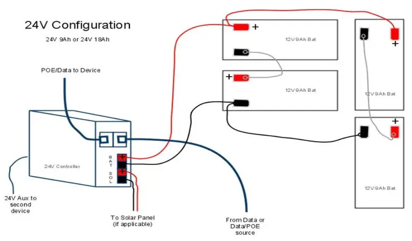
STEP 4: Route wire from the solar panel into the enclosure and connect to the controller solar panel input. Make sure to maintain correct polarity.STEP 5: Install batteries to enclosure using Velcro straps.If the Solar Controller is model TP-SC12xx you must wire batteries and solar for 12V configuration. If the Solar controller is model TP-SCPOE-24xx you must wire solar panels and batteries for 24V configuration.STEP 6: Connect the Battery cables to Controller BAT terminals and then to the batteries. Be sure to observe polarity. The black wire connects to the battery negative terminal and BAT(-) terminal on the controller. When a fully charged battery is connected, the Green LOA LED should light on the controller, and power should be present on POE output (pins 4,5,7,8) and also back green wire terminal connector.STEP 7: Make sure the lid gasket is clean and free from any particles, then carefully close the cover, making sure that wires are clear of the seam and hinge area. The cover snaps into place. There is one center security bolt that can be used to secure the cover.NOTE: If you have any unconnected battery connectors on the battery cable after installation, make sure they are wrapped with electrical tape so that there is no chance of shorting the connector to any metal. You can also remove the extra cable/connector permanently by cutting the cable at the existing battery connection.
Controller Wire Terminal Output Wiring

SPECIFICATIONS
| RPPL12 | RPPL24 | |
| Continuous Power Rating | 8W | |
| Maximum Power Rating | 30W | |
| Reserve Power @ 8W Load | 27 hours | |
| Battery Voltage (DC) | 12V | 24V |
| POE Output Voltage (DC) | 24V or 48V | 24V or 48V |
| POE Input Voltage (DC) | 18-57V © 2.5A | 36-57V © 2.5A |
| Battery Capacity (max) | 36Ah | 18Ah |
| Battery Type | Valve Regulated Sealed Lead Add / Absor-bent Glass Mat (AGM) | |
| Battery Life | 5 Years | |
| Controller Type | Dual Input Solar/POE.PWM.12V 10ASuggested Max SolarPanel Size 135W | Dual Input Solar/POE. PWM.24V 10ASuggested Max SolarPanel Size 270W |
| Overcharge Protection | 14.4V | 27.3V |
| Over-discharge protection | 11V | 20V |
| Over-discharge recovery | 12V | 24.3V |
| Self Consumption | <0.5W | |
| Enclosure Type | Polycarbonate | |
| Enclosure External Size | 6″
17.5 x 12.5 x (445 x 318x 152mm) |
|
| Enclosure Internal Size | 14 x 10 x 5″(356 x 254 x 127mm) | |
| Space for Customer Equip | 3 x 5 x 3″(76 x 127 x 76mm) | |
| Operating Temperature | -30°C to +60°C | |
| System Weight (no batts) | 4Ib (1.8kg) | |
| Battery Weight (each) | 2.5kg (5.51b) |
TECH CORNER
Additional Information you may find useful
- CONTROLLER: The 12V controller turns off power to the load at 11V and reconnects when the battery reaches 12V. The 24V controller turns off at 20V and on at 24V. This protects battery from over-discharge and increases battery life and performance.
- CAPACITY: The RemotePro® RPPL with a 30W panel is rated at 8W continuous power output with 6 hours of peak sun per day. Reserve battery capacity at 8W load is 27 hours with 36Ah of battery.
| Place | Optimum Winter Tilt |
| Houston / Cairo | 56 deg |
| Albuquerque / Tokyo | 60.5 deg |
| Denver / Madrid | 65 deg |
| Minneapolis / Milano | 69.5 deg |
| Winnipeg / Prague | 74 deg |

3. VENTING: The enclosure is vented thru the wire feedthrus in the bottom of the enclosure. Don’t make these airtight with silicon.4. BATTERY MAINTENANCE: The batteries used in the RemotePro® systems don’t require any maintenance. They should last up to 5 years in normal use. Note: Never store batteries for any length of time in a discharged state or it will damage the battery.5. SOLAR PANEL TILT: There is a solar panel tilt calculator at the Ty- con Systems® website. We recommend using a fixed tilt and setting to optimize for winter sun. The panel should face South if you are in the Northern Hemisphere and face North if you are in the Southern Hemisphere. You can also calculate proper winter tilt using: Your_Latitude * 0.9 +307. BATTERY OVERDISCHARGE: We highly recommend hooking all equipment loads to the control voltage output. This output will disconnect the load if the battery voltage drops below 11V/20V and this will protect the battery from over-discharge. If batteries get completely discharged because the equipment was connected directly to the battery, you will reduce the battery life and you will most likely need to supercharge them with a good quality 10A automotive battery charger. Don’t charge for more than 8hrs on an automotive charger. Once they are back to a normal operating range, the integrated charge controller will maintain the charge.8. TROUBLESHOOTING:A. I only get the SOL light on my charger controller?–The battery voltage and solar panel voltage must match the controller. If a controller is TP-SCPOE-12xx it needs 12V solar and battery voltage. If the model is TP-SCPOE-24xx it needs a 24V battery and solar voltage.B. There is no LOA light and no voltage output?–If battery voltage is too low, the charge controller will turn off the load outputs. On a 12V battery system, the load will turn off if the battery is <11V. On a 24V battery system, the load will turn off at <20V.C. Why is my solar panel voltage so high?– Open circuit voltage on a 12V panel is around 23V, and about 40V on a 24V panel. Once you connect to the charge controller the panel voltage will be reduced to a little higher than the battery voltage.D. My system turns off at night and comes back on in the morning?– This is a sure sign that the solar panels and/or battery capacity can’t support the load. You should measure your actual load and recalculate to make sure you have adequate capacity.
 report this ad
9. WIND TURBINE: A wind turbine can be added to this system at any time. Wind Turbines are good sources of power, often in times when the sun isn’t shining, like on stormy days. We like to think of a wind turbine as uptime insurance. Tycon SolarTM offers small wind turbines perfectly suited to augment the RemotePro® systems. The Tycon® BreezePro® (TPW-400DT-12/24) are compatible wind turbines. To add a wind turbine, it mounts to the top of a 41mm inside diameter pole.
 10. POE SWITCH: Tycon Power® offers a universal voltage 5port and 8port POE switch if more than one device needs to be powered from the battery system. The TP-SSW5-NC, TP-SW5G-NC, and TPSW8-NC offer the unique feature that the voltage supplied to the switch is the POE voltage sent to the devices. So 24VDC in and you get 24VDC POE to the devices. The operating voltage is 12V to 56VDC.11. OTHER ACCESSORIES: Tycon® also offers a variety of voltage conversion products to meet almost any need.
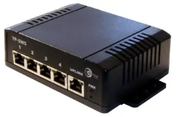
Limited Warranty
The RemotePro® products are supplied with a limited 36-month warranty which covers material and workmanship defects. This warranty does not cover the following:
- Parts requiring replacement due to improper installation, misuse, poor site conditions, faulty power, etc.
- Lightning or weather damage.
- Physical damage to the external & internal parts. Products that have been opened, altered, or defaced.
- Water damage for units that were not mounted according to user manual.
- Usage is other than in accordance with instructions and the normal intended use.
NOTES8000014 Rev 7 RPPL RemotePro® Qwik Install Guide
[xyz-ips snippet=”download-snippet”]