
Renogy DC-On Board Battery Charger
Important Safety Instructions
This manual contains important safety, installation , and operating instructions for the charge controller. The following symbols are used throughout the manual to indicate potentially dangerous conditions or important safety information.
Safety instruction: Failure to observe this instruction will result in fatal or serious injury.Safety instruction: Failure to observe this instruction can result in fatal or serious injury.Safety instruction: Failure to observe this instruction can lead to injury.Note: Failure to observe this instruction can cause material damage and impair the function of the product.Note: Supplementary information for operating the product.
The manufacturer accepts no liability for damage in the following cases:
- Faulty assembly or connection
- Damage to the product resulting from mechanical influences and excess voltage
- Modification of the unit without expressed permission from the manufacture
- Use for purposes other than those described in the operating manual
For protection, pay close attention to the following basic safety information when using electrical devices:
- Electric shock
- Fire hazards
- Injury
General safety
- In the event of fire, use a fire extinguisher that is suitable for electrical devices.
- Only use the product as intended.
- Ensure that the red and black terminals never come into contact with each other.
- Disconnect the product from the battery
- each time before cleaning and maintenance
- before a fuse change (only by specialists)
- The product may not be used if the product itself or the connection cable is visibly damaged.
- If the power cable for this product is damaged, it must be replaced by the manufacturer, customer service, or a similarly qualified person in order to prevent safety hazards.
- This product may only be repaired by qualified personnel. Inadequate repairs may cause serious hazards.
- Electrical devices are not toys
- Always keep and use the product out of the reach of children.
- Children must be supervised to ensure that they do not play with the product.
- Before start-up, check that the voltage specification on the type plate is the same as that of the power supply.
- Ensure that other objects cannot cause a short circuit to the contacts of the product
- Store the product in a dry and cool place
Safety when installing the product
- Never mount the product in areas where there is a risk of gas or dust explosion.
- Ensure a secure stand!The product must be set up and fastened in such a way that it cannot tip over or fall down.
- Do not expose the product to any heat source (such as direct sunlight or heating). Avoid additional heating of the product.
- Set up the product in a dry location protected from splashing water.
Safety when connecting the product electronically
Danger of fatal electric shock!
- For installation on boats: If electrical devices are incorrectly installed on boats, this can lead to corrosion damage on the boat. Have the product installed by a qualified (boat) electrician.
- If you are working on electrical systems, ensure that there is somebody close at hand who can help you in emergencies.
- Make sure that the lead has a sufficient cross-section.
- Lay the cables so that they cannot be damaged by the doors or the bonnet. Crushed cables can lead to serious injury.
- Lay the cables so that they cannot be tripped over or damaged.
- Use ductwork or cable ducts if it is necessary to lay cables through metal panels or other panels with sharp edges.
- Do not lay the AC cable and DC cable in the same conduit (empty pipe).
- Do not lay the cables so that they are loose or heavily kinked.
- Firmly secure the cables. contact with each other.
- Do not pull on the cables.
Safety when operating the product
- If the product is used in facilities with open lead acid batteries, the room must be well-ventilated. These batteries give off explosive hydrogen gas that can be ignited by sparks on electrical connections.
- Do not operate the product
- In salty, wet, or damp environments
- In the vicinity of corrosive fumes
- In the vicinity of combustible materials
- In areas where there is a danger of explosions
- Before activating, ensure that the power supply line and plug are dry.
- Always disconnect the power supply when working on the product.
- Please be aware that parts of the product may still produce voltage even after ac livalion of the safety guard (fuse).
- Do not disconnect any cables while the product is still in use.
- Make sure the air inlets and outlets of the product are not covered.
- Ensure good ventilation.
- Batteries may contain aggressive and corrosive acids. Avoid battery fluid coming into contact with your body. If your skin does come into contact with battery fluid, thoroughly wash that part of your body with water.If you sustain any injuries from the acids, contact a doctor immediately.
CAUTION:
- When working on batteries, do not wear any metal objects such as watches or rings. Lead acid batteries can cause short circuits which can cause serious injuries.
- Danger of explosions!Never attempt to charge a frozen or defective battery.In this situation, place the battery in a frost-free area and wait until the battery has adjusted to the ambient temperature. Then start the charging process.
- Wear goggles and protective clothing when you work on batteries. Do not touch your eyes when working with batteries.
- Do not smoke and ensure that no sparks can arise in the vicinity of the engine or battery.
NOTICE:
- Only use rechargeable batteries
- Use sufficient cable cross sections.
- Protect the positive conduit with a fuse.
- Prevent any metal parts from falling on the battery. This can cause sparks or short circuit the battery and other electrical parts.
- Make sure the polarity is correct when connecting.
- Follow the instructions of the battery manufacturer and those of the manufacturer of the system or vehicle in which the battery is used.
- If you need to remove the battery, disconnect it first from the ground connection. Disconnect all connections from the battery before removing it.
General Information
The DC-DC Series battery chargers are the most effective way to charge your auxiliary or house batteries from the alternator/starter battery. Compatible with a multitude of alternator types, the DC-DC offers correct charging for AGM, Flooded, Gel, and even Lithium deep cycle batteries! Featuring a 3-stage battery charger and multiple electronic protections, owners can feel confident that their batteries are being charged optimally and automatically. Easily install the compact yet sturdy DC-DC on RV’s, commercial vehicles, boats, yachts and many more applications.
Key Features
- Compatible with multiple 12V batteries: AGM, Flooded, Gel, and Lithium*
- Smart protections features including Over-voltage, Over-Temperature, and reverse polarity!
- Battery Isolation and Battery Charger in one
- Compact yet built tough for all conditions
- 3-Stage Battery Charger get your batteries to 100%
Check the charging requirements from the battery manufacturer before charging your battery with this unit.
Product Overview
Identification of Parts
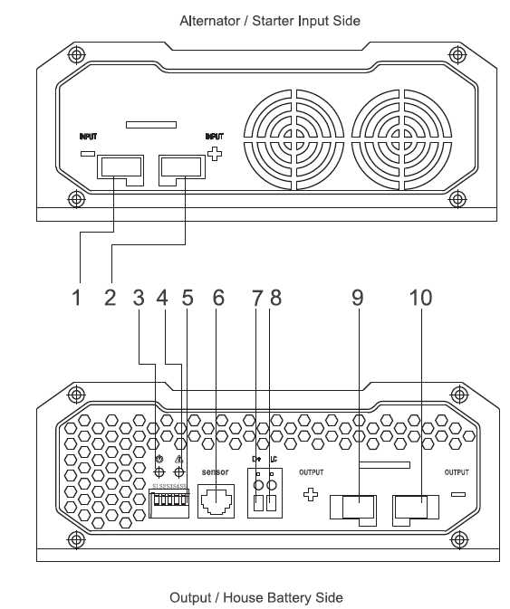
Key Parts
| Key Part# | Labeling | NOTES |
| 1 | Input(-) | Negative (-) Input Terminal of the Starter Input |
| 2 | Input(+) | Positive (+) Input Terminal of the Starting Source |
| 3 | DC-DC Power Indicator | |
| 4 | DC-DC Fault Indicator | |
| 5 | S1 S2 S3 S4 S5 | DIP Switches (1-5) Set Charging Voltage and Float Voltage for Battery |
| 6 | RJ11 | Battery Temperature Sensor (SKU: RTSDCC-G1) Port; uses this data for accurate temperature compensation and charge voltage adjustment |
| 7 | D+ | Alternator Control terminal for turning on the vehicle with on-board battery or Ignition
*Note requires wired to turn on DC-DC; 18-16AWG recommended . |
| 8 | LC | Current Limit: Limits the charging amperage to 12.5% of the rated input for the 20A and 40A models and limits the charging amperage to 50% for 60A models. |
| 9 | Output (+) | Positive (+) Output Terminal for House Battery |
| 10 | Output (-) | Negative (-) Output Terminal for House Battery |
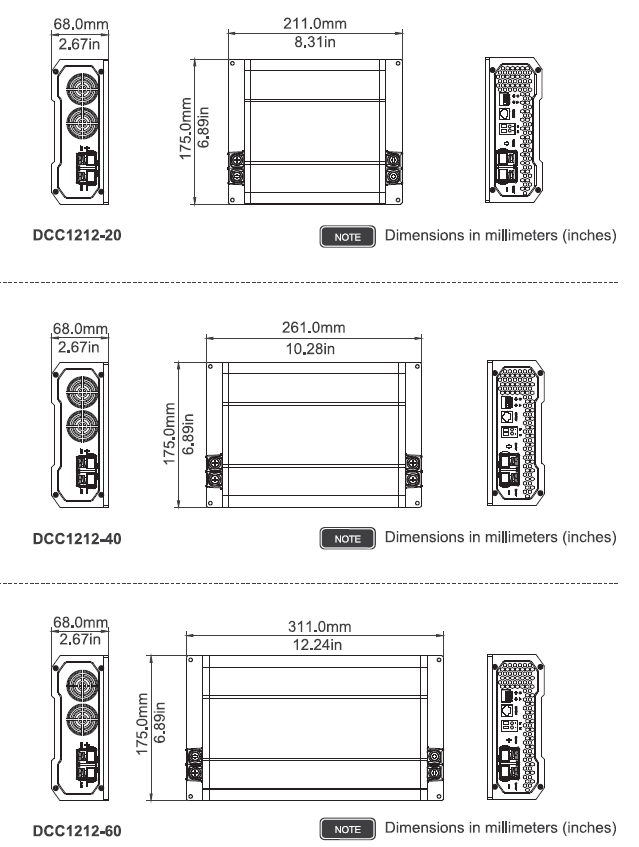
Dimensions
Package Includes
| 1 | DC-DC Battery Charger |
| 2 | Manual
Please Note: You will find the most up to date manual at www.renogy.com under the download section. |
Accessories
The following accessories are not included in the packaging, but available for purchase. Battery Temperature Sensor (SKU: RTSDCC-G1)
Installation
Note:
- Never mount the product in areas where there is a risk of gas or dust explosion.
- Ensure a secure stand! The product must be set up and fastened in such a way that it cannot tip over or fall down.
- Do not expose the product to any heat source (such as direct sunlight or heating). Avoid additional heating of the product.
- Set up the product in a dry location protected from splashing water.
Location Considerations
- The battery charger can be installed horizontally as well as vertically.
- The battery charger must be installed in a place that is protected from moisture.
- The battery charger may not be installed in the presence of flammable materials.
- The battery charger may not be installed in a dusty environment.
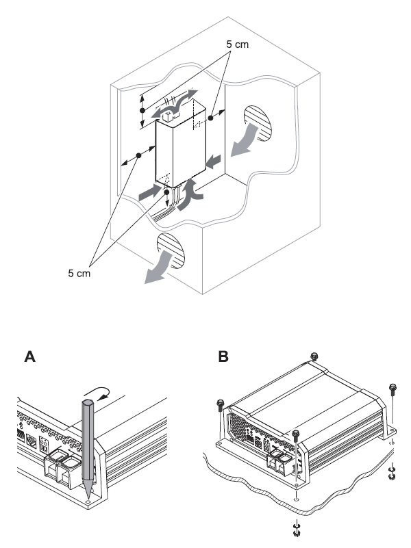
- The place of installation must be well ventilated. A ventilation system must be available for installations in small, enclosed spaces. The minimum clearance around the battery charger must be at least 5cm.
- The device must be installed on a level and sufficiently sturdy surface.
When selecting a location for the DC-DC, make sure that the unit is as close as possible to the battery you will be charging (auxiliary battery). The charger may be mounted on the cabin of the vehicle, along a chassis rail, the inner guard of a vehicle, behind the grille or headlight or even on the side of the radiator. However, you want to make sure that the area is not susceptible to moisture or other substances as well as potentially high temperatures. The DC-DC would operate best if there is some air flow.
Mounting Battery Charger
Cable Cross Section
*The following is a reference and may not cover all the unique applications that may exist. Consult your installer for further questions.Important Note: When the battery charger is sending full amps, the input side will experience a higher draw.
| Cable | Cable Length/ Min AWG | Recommended Fuse | ||||
|
DCC-1212-20 |
To starter Battery (input) | 2FT /
10AWG |
8FT /
10AWG |
16FT /
8AWG |
32FT /
4AWG |
30A |
| To house Battery (output) | 2FT / 14-
12AWG |
8FT / 14-
12AWG |
16FT /
10AWG |
32FT /
6AWG |
25A |
|
|
DCC-1212-40 |
To starter Battery (input) | 2FT /
6AWG |
8FT /
6AWG |
16FT / 6-
4AWG |
32FT / 4-
2AWG |
60A |
| To house Battery (output) | 2FT /
8AWG |
8FT /
8AWG |
16FT /
6AWG |
32FT /
4AWG |
50A |
|
|
DCC-1212-60 |
To starter Battery (input) | 2FT /
4AWG |
8FT /
4AWG |
90A |
||
| To house Battery (output) | 2FT /
6AWG |
8FT /
6AWG |
16FT /
4AWG |
75A |
- When charging converter is sending full charge, the amperage consumption will be 50% greater on the input side.
- The charging converter must not be connected directly to the alternator.
Connecting the Battery Charger
The DC-DC will not turn on without a D+ ignition cable. When connected, the DC-DC will turn on when the ignition is on. This means that even if your engine is not on, the starter battery will immediately be used to power the DC-DC and start charging the house battery. It is recommended to have the vehicle completely on.
Note: battery charger has isolated input and output voltages, which means that the output voltage can be kept stable without interference from the input circuit. When connecting the signal wires, the battery charger will be on a stable 12VDC voltage.
- Identify the correct side of the DC-DC corresponds to the correct battery. The Input side will be the Starting Source while the output side will be the Auxiliary/ House Battery side ..IMPORTANT: A D+ ignition cable is required to turn the unit on. Although the D+ terminal is in the output side, this will be connected to the positive line of the input ignition circuit.

Note: The D+ Terminal will connect to the positive line of the input ignition circuit
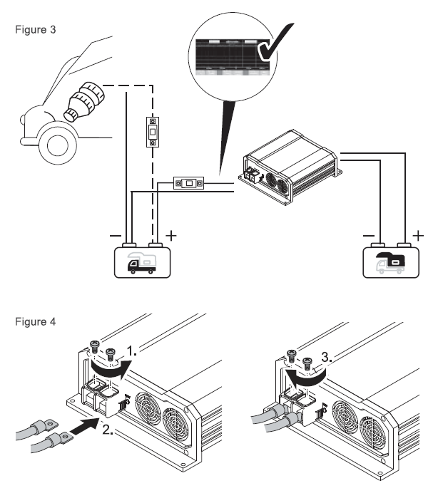
- 2. Unscrew the terminals, connect the common negative and common positive wires from the starter battery to the input of the DC-DC in the appropriate negative and positive terminals. Then screw the terminals for a tight fit. Refer to Figure 3 and Figure 4.Important Note: The Alternator will not be connected directly to the input of the DC- DC. The alternator must be integrated with the starter battery and this circuit is connected to the input starter source terminals on the DC-DC.
- Connect a copper signal cable (not provided), 18-16AWG, to the D+ slot on the DC-DC output side and run the cable to the positive terminal of your starter input ignition circuiUstarter battery common positive. Refer to figure 5. The unit should then turn on.Note: The DC-DC will turn on when the ignition is on. This means that even if your engine is not on, the starter battery will immediately be used to power the DC-DC and start charging the house battery. It is recommended to have the vehicle completely on.
IMPORTANT: AD+ ignition cable is required to turn the unit on. Although the D+ terminal is in the output side, this will be connected to the positive line of the input ignition circuit.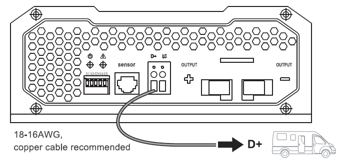
Operation
When the input and output batteries as well as the signal wire is connected, the DC-DC will power on with green LED.IMPORTANT: The DC-DC will not turn on without a D+ ignition cable, Connected to the positive line of the input ignition circuit.
LED Indicator
| Color, Behavior | Status | Description |
| Off | No Load | Unit is off; If abnormal, see troubleshooting for more detail. |
| Green | Operation Normal | |
|
Red |
Fault | There is an error in your system, see troubleshooting for more detail |
Setting Battery Charger
The battery charger is for AGM, Sealed Lead Acid, Flooded, and Gel batteries. If using Lithium, the charger is for lithium-iron phosphate battery types with a built-in BMS system. Do not use the device under any circumstances to charge other types of batteries (ex. NiCd, NiMH, etc.)
Warning: Danger of Explosion! *Note: Check the charging requirements from the battery manufacturer before charging your battery with this unit.
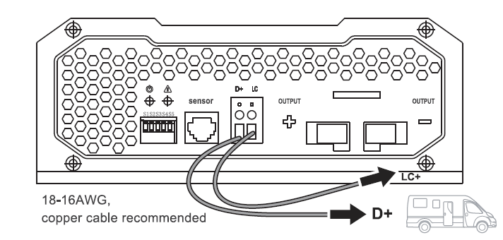
Note: make sure to abide by the safety instructions in the beginning of the manualThe DC-DC is equipped with 5 DIP switches which determine the boost charge and float charge profiles, depending on your battery specifications. Refer to the diagram for ON/OFF position respectively.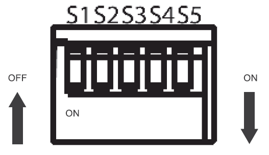
| DIP Switch | Description | |
| S5 | Determines whether the charging batteries or for others battery types | |
| S1, S2 | Determines the Constant Voltage for your battery charging profile | |
| S3, S4 | Determines the Float Voltage for your battery charging profile
*This will not be used for lithium batteries |
Start with SW5 to determine whether you are charging a lead-acid battery or lithium
Set charging mode
You can set the charger mode using the S5 and switches.
| ON Charging mode of lead-acid battery |
| OFF Charging mode of Lithium-ion battery |
*Please note that the charging profile will automatically bulk before approaching the user-defined absorption and float stage.
IMPORTANT: The DC-DC will not turn on without a D+ ignition cable so you will still need to have this connected when and if utilizing the LC terminal. Although the LC terminal is in the output side, this will be connected to the positive line of the Input Starter Side.
Battery Charging Logic
The charging characteristics are referred to as IUOU characteristics. 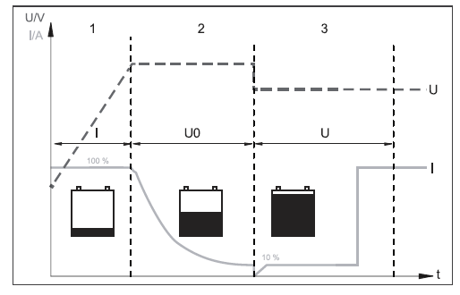
1: I phase (bulk)At the beginning of the charging process, the flat battery is charged with a constant current (100 % charge current) until the battery voltage reaches the charging end voltage. The charging current decreases when the battery has reached this charging level.
2: UO phase (absorption)Now the absorption charging process (UO phase) begins, where the duration depends on the battery. The voltage remains constant (UO).This phase is limited to a maximum of 3 hours to prevent overcharging the battery while driving.
3: U phase (float)After the UO phase, the battery charger switches to the conservation charging function (U phase).
Troubleshooting
The manufacturer accepts no liability for damage in the following cases:
- Faulty assembly or connection
- Damage to the product resulting from mechanical influences and excess voltage
- Alterations to the product without expressed permission from the manufacturer
- Use for purposes other than those described in the operating manual
Note:
Do not open the device. You risk exposing yourself to an electric shock by doing this.If you have detailed questions about the battery charger, please contact our customer support (addresses on the back of the instruction manual).
| Behavior | Troubleshoot Steps |
| Green LED not turning on, but the batteries are connected | 1.Check the D+ signal wire and make sure it is connected to the input alternator/battery positive and the D+ port on the DC-DC |
| 2.Make sure the Input starter source is connected to the input terminals of the DC-DC and the house battery is connected to the output terminals on the DC-DC. | |
| 3.Check to make sure your connections are tight and secured and that it is connected to the correct terminals. | |
| 4.There may be a break in your connection so Inspect all wires for tears or breaks and if all is well on the surface, then conduct a continuity test using a multi-meter to check for adequate now. This will depend on your model. | |
| 5.Use a multi-meter to check that the both the starter and house batteries are within the DC-DC voltage specification. It should not be under 8V or over 16V. | |
| 6.Use a multi-meter to also verify whether your poles are reversed. Setting your multi-meter to DC Volts, probe the positive line onto the positive battery terminal and probe the negative line to the negative battery terminal. If the DC reading is negative, your poles are reversed. | |
| 7.You may need to conduct a battery test at your local auto shop | |
| Unit was working, but then shutdown. | If the DC-DC is not functioning properly, it may be undergoing an automatic protection function. This does not mean the DC-DC is defective, but it requires some adjustments to commence normal system operation. The red indicator may or may not be on, depending on the circumstance. |
Protection Function / Fixes
LED is Red, what do I do?
| Functions | Fixes |
| Over-Voltage Protection; Under-Voltage Protection | 1.Use a multi-meter to check the voltage of the battery bank to confirm whether the starter battery or house battery is above specification (16V) or below the specification (8V) |
| 2.lf above the voltage specification, disconnect all loads and chargers from the battery and allow the battery to stabilize. This may take a few hours. | |
| 3.lf below the voltage specification, you will need an external charger to bring the battery voltage to the minimum set point on the DC-DC. The under-voltage protection may not be showing an indicator light. | |
| Reverse-Polarity Protection | 1.Use a multi-meter to also verify whether your poles are reversed. Setting your multi-meter to DC Volts, probe the positive line onto the positive battery terminal and probe the negative line to the negative battery terminal. If the DC reading is negative, your poles are reversed. |
| 2.Switch the poles to resume normal operation | |
| High-Temperature Protection | 1.lf voltage checks out fine, then the installation area may be too hot for the DC-DC to operate. |
| 2.Turn off any loads from the DC-DC and if you have a temperature sensor, measure the temperature to make sure it is not outside of working specification 50(degree) C. | |
| 3.Ventilate the installation area, or let the unit sit until it has cooled down via temperature sensor or your touch. | |
| 4.The high-temperature protection is automatic and will resume normal operation upon detecting lower temperatures/operational temperatures. | |
| Short Circuit Error | If the troubleshooting steps or protection function steps are ineffective at fixing the DC-DC, then it may be experiencing an internal short circuit error. The LED will be permanently on and cease to function, by which it will need to be replaced. |
Technical Specifications
| RNG-DCC1212-20 | RNG-DCC1212-40 | RNG-DCC1212-60 | |
| Transformation | 12v-12v | ||
| Nominal input voltage | 12 voe | ||
| Input voltage range | 8V ~ 16VDC | ||
| Rated Charging Current | 20A | 40A | 60A |
| Charging Voltage Range | 13.2V – 14.7V, depending on DIP Switch | ||
| Max Rated Output Power | 250W | 500W | 750W |
| Residual ripple of output voltage at rated current |
< 50 mV @20A / 40A / 60A |
||
| Efficiency | up to 90 % | ||
| Idle power consumption | < 0.4 A | ||
| Operational temperature | -20 °C – +50 °C -4°F ~122°F | ||
| Temperature
Compensation (with sensor) |
-3Mv/C®/2V (See Chart) |
||
| Humidity | $95 % Non-condensing | ||
| Dimensions (W x D x H): | 211x175x68mm 8.31 x 6.89 x 2.68in | 261x175x68mm 10.28 x 6.89 x 2.68in | 311x175x68mm 12.24 x 6.89 x 2.68 |
| Terminal Size | MS x 10mm, 1mm thread pitch | ||
| Weight | 1.33 kg.
2.93 lbs. |
1.88 kg
4.14 lbs. |
2.40 kg
5.29 lbs. |
| Inspection / certification | CE |
Temperature Compensation
Please Note: The temperature compensation is not to be used with lithium batteries.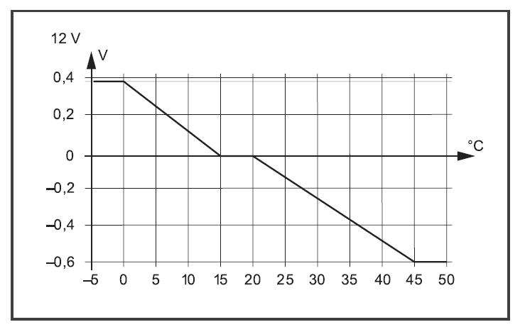
Protective Function Specifications
| @Input | High-Voltage, low-voltage, reverse polarity, high-temperature, short-circuit |
| Low-voltage cut-out | 8V |
| Low-voltage restart | 10V |
| High-voltage shutdown | 16V |
| High-voltage restart | 15.5V |

2775 E Philadelphia St, Ontario, CA 91761, USA 909-287-7111 www.renogy.com[email protected]
[xyz-ips snippet=”download-snippet”]