RENOGY Dual Input DC-DC On Board Battery
Charger w/ MPPT User Manual


Important Safety Instructions
Please save these instructions.
This manual contains important safety, installation, and operating instructions for the DCDC Battery Charger. Do not operate the Battery Charger unless you have read and understood this manual and the charger is installed as per these installation instructions. Renogy recommends that the charger be installed by a qualified professional. Store it in a safe place. The following symbols are used throughout the manual to indicate potentially dangerous conditions or important safety information.

The manufacturer accepts no liability for damage in the following cases:
- Faulty assembly or connection.
- Damage to the product resulting from mechanical influences and excess voltage.
- Alterations to the product without expressed permission from the manufacturer.
- Use for purposes other than those described in the operating manual.
For protection, pay close attention to the following basic safety information when using electrical services:
- Electric shock
- Fire hazards
- Injury
General Safety
DANGERIn the event of fire use a fire extinguisher that is suitable for electrical devices.
WARNING
- Only use the product as intended.
- Make sure all connections going into and from the product are tight
- Disconnect the product from the battery—-each time before cleaning and maintenance—-before a fuse change (only by specialists)
- Do NOT allow water to enter the product—-Detach all connections.—-Make sure that no voltage is present on any of the inputs and outputs.
- The product may not be used if the product itself or the connection cable is visibly damaged.
- This product may only be repaired by qualified personnel. DO NOT disassemble or attempt to repair the unit. Inadequate repairs may cause serious hazards.
- Electrical devices are not toys.Always keep and use the product out of the reach of children.
- Children must be supervised to ensure that they do not play with the product.
NOTE
- Before start-up check that the voltage specification on the plate is the same as that of the power supply.
- Ensure that other objects cannot cause a short circuit to the contacts of the product.
- Store the product in a dry and cool place.
Safety when connecting the product electronically
DANGERDanger of fatal electric shock!
- For installation on boats:If electrical devices are incorrectly installed on boats this can lead to corrosion damage on the boat. Have the product installed by a qualified (boat) electrician.
- If you are working on electrical systems, ensure that there is somebody close at hand who can help you in emergencies.
WARNING
- Make sure that the cables has a sufficient cross-section.
- Lay the cables so that they cannot be damaged by the doors or the bonnet. Crushed cables can lead to serious injury.
CAUTIONLay the cables so that they cannot be tripped over or damaged.
NOTICE
- Use ductwork or cable ducts if it is necessary to lay cables through metal panels or other panels with sharp edges.
- Do not lay the AC cable and DC cable in the same conduit (empty pipe).
- Do not lay the cables so that they are loose or heavily kinked.
- Firmly secure the cables, contact with each other.
- Do not pull on the cables
Charger Safety
NOTICE
- NEVER connect the solar panel to the charger without a service battery connection. The Battery must be connected first.
- Ensure the PV input voltage does not exceed 25 Vdc to prevent permanent damage. Use the Open Circuit Voltage (Voc) at the lowest temperature to make sure the voltage does not exceed this value when connecting panels together.
Battery Safety
WARNINGBatteries may contain aggressive and corrosive acids. Avoid battery fluid coming into contact with your body. If your skin does come into contact with battery fluid, thoroughly wash that part of your body with water. If you sustain any injuries from the acids contact a doctor immediately.
CAUTION
- When working on batteries, do not wear any metal objects such as watches or rings. Lead acid batteries can cause short circuits which can cause serious injuries.
- Danger of explosions!Never attempt to charge a frozen or defective battery. In this situation place the battery in a frost-free area and wait until the battery has adjusted to the ambient temperature. Then start the charging process.
- Wear goggles and protective clothing when you work on batteries. Do not touch your eyes when working with batteries.
- Do not smoke and ensure that no sparks can arise in the vicinity of the engine or battery.
NOTICE
- Only use rechargeable batteries.
- Use sufficient cable cross sections.
- Protect the positive conduit with a fuse.
- Prevent any metal parts from falling on the battery. This can cause sparks or short circuit the battery and other electrical parts.
- Make sure the polarity is correct when connecting.
- Follow the instructions of the battery manufacturer and those of the manufacturer of the system or vehicle in which the battery is used.
- If you need to remove the battery, disconnect it first from the ground connection. Disconnect all connections from the battery before removing it.
General Information
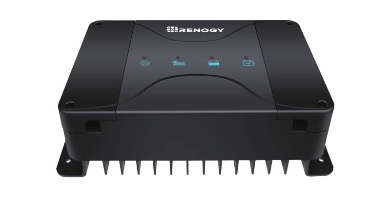
The Renogy Dual Input DC-DC On Board Battery Charger w/ MPPT is designed to charge your service battery to 100% from two inputs: solar and alternator. Featuring multi-battery compatibility including Lithium, this DCDC utilizes alternator power, solar power with MPPT technology, or both to make sure that you’re always charged and can enjoy being off the grid longer!
Key Features
Designed to charge service batteries from two DC inputs–solar panels and alternator Built-in Maximum Power Point Tracking (MPPT) to maximize the solar power 3-phase charging profile (Bulk, Boost, and Float) ensures your service battery will be accurately charged at the correct voltage levels to 100% Compatible with smart alternators (with variable output voltage) Trickle charges the starting battery via solar panels if the service battery is fully charged Isolation of the starting battery and the service battery Temperature and voltage compensation features prolong battery life and improve system performance Smart Protection Features: battery isolation, over-voltage protection, battery temperature protection, over-current protection, overheat protection, reverse current protection, solar panel and alternator reverse polarity protection Compatible with multiple battery types: Sealed, AGM, GEL, Flooded, and Lithium Compact with a sturdy design, it was built tough for all conditions
Product Overview
Identification of Parts

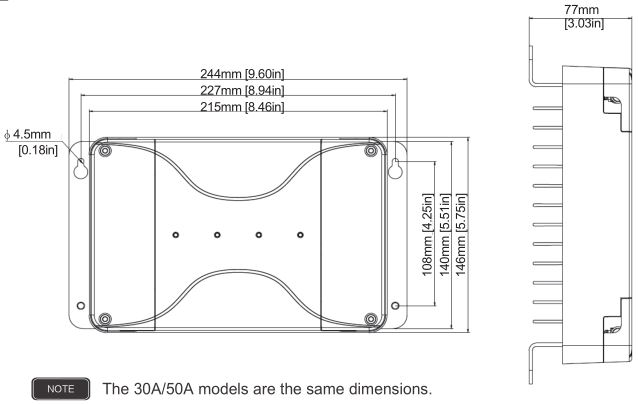
Dimensions
Additional Components
Additional components included in the package:
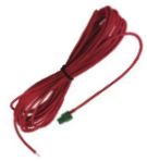
Battery Temperature SensorThe proper battery charging voltage is important for optimum battery performance and longevity. This Remote Temperature Sensor measures temperature at the battery, allowing the DC-DC charger to use this data for accurate temperature compensation and charge voltage adjustment.NOTE No temperature compensation when charging lithium battery.
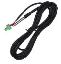
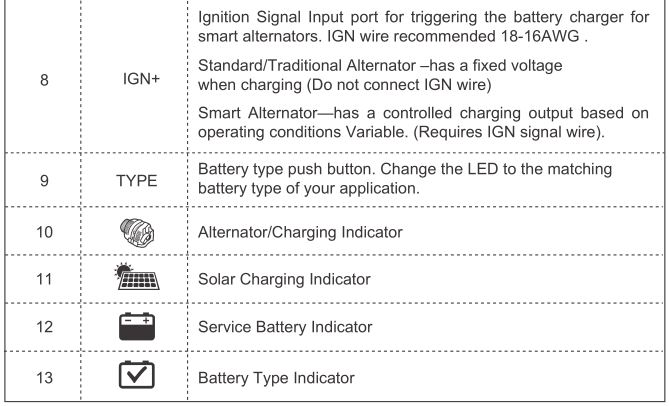
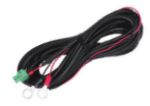
IGN Signal Wire for Smart AlternatorSmart alternators allows the vehicle to control the output voltage depending on the operating conditions whereas traditional alternators output a fixed higher voltage. If your readings are around 14.4V DC then then you most likely have the traditional, non-smart alternator. If your reading is closer to 12.5-13.5V then it’s likely that you have a smart alternator. Check with your vehicle manufacturer to determine alternator status.NOTE Not connected if using traditional alternator. IGN wire recommended 18-16AWG .
RS485 Communication CableCommunication cable for RS485 port for App and Monitoring Screen; future development.

Optional Components
Optional components require a separate purchase.
Battery Voltage Sensor (RVSCC)The Battery Voltage Sensor provides users with more accurate battery charging giving you peace of mind that the charge controller is operating as effectively as it should. On certain applications with long line runs, there can be a difference between the voltage measured at an MPPT/PWM solar charger’s terminals and that measured at the battery terminals. The BVS is the perfect solution by providing a more accurate battery voltage to the controller and allowing it to adjust the charging stage more precisely resulting in overall extension of your battery life.
Installation
Mount the Battery Charger
DANGERNever mount the product in areas where there is a risk of gas or dust explosion.
CAUTIONEnsure a secure stand! The product must be set up and fastened in such a way that it cannot tip over or fall down.
NOTICE
- Do not expose the product to any heat source (such as direct sunlight or heating). Avoid additional heating of the product.
- Set up the product in a dry location protected from splashing water.
Location Considerations
- The battery charger can be installed horizontally as well as vertically.
- The battery charger must be installed in a place that is protected from moisture.
- The battery charger may not be installed in the presence of flammable materials.
- The battery charger may not be installed in a dusty environment.
- The place of installation must be well ventilated. A ventilation system must be available for installations in small, enclosed spaces. The minimum clearance around the battery charger must be at least 5cm.
- The device must be installed on a level and sufficiently sturdy surface.
When selecting a location for the DCDC, make sure that the unit is as close as possible to the battery you will be charging (auxiliary battery). The charger may be mounted on the cabin of tthe vehicle, along a chassis rail, the inner guard of a vehicle, behind the grille or headlight or even on the side of the radiator. However, you want to make sure that the area is not susceptible to moisture or other substances as well as potentially high temperatures. The DCDC would operate best if there is some air flow.
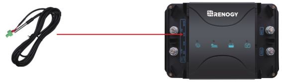
Connecting Temperature Sensor
The temperature sensor will have a green housing connector on one end and a metal probe on the other. Simply align and connect the green housing to the BTS terminal on the DCDC. Place the probe end of the sensor near or on top of the battery to monitor temperature in the area.
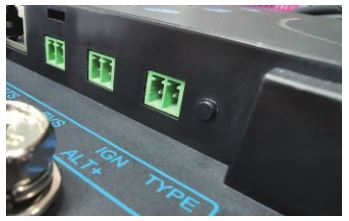
Connecting IGN Signal Wire
Connect the positive line to one of green housing ports on the IGN port. You will need to open the wire terminal utilizing the screws on top of the green housing. You will then connect the positive line of the IGN to the ignition circuit.
Standard/Traditional Alternator has a fixed voltage when charging (Do not connect IGN wire)
Smart Alternator–has a controlled charging output based on operating conditions. Variable. (Requires IGN signal wire)
NOTEThere are two ports on the green IGN connector housing. Both ports have a positive polarity, so only one connection is required from either port.

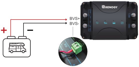
Connecting Battery Voltage Sensor
Connect the Battery Voltage Sensor connector to the BVS port. Connect the positive line to the left side of the green housing and then connect the negative line to the right side of the green housing. You will need to open the wire terminal utilizing the screws on top of the green housing. You will then need to place the bare wire end onto the respective battery terminal for accurate voltage sensing.BVS+ BVS-
Selecting the Battery Type
To change the battery type you will need to press the push button that is located on the PV+ and ALT+ side of the DCDC. The following chart indicates the Battery Type LED .
NOTEUser mode is an extra feature accessed via App or Monitoring Screen; Future Development
Connect the Battery Charger
WARNINGDo not reverse the polarity. Reverse polarity of the battery connections can cause injury and damage the device.
CAUTION
- Avoid coming into contact with the battery fluid under any circumstances.
- Batteries with a cell short circuit should not be charged as explosive gases may form due to the battery overheating.
- Be careful not to over-torque the terminals on the DCDC. Over-torquing may cause irreparable damage. Do not exceed 16 N-m / 3.3 ft-lb
NOTE
- Make sure the battery poles are clean when connecting the terminals.
- Select a sufficient cross-section for the connection cable.
- Use the following cable colors:—-Red: positive connection—-Black: negative connection
- Tighten the nuts and bolts with proper torque. Loose connections may cause overheating.
For safety, please always connect ground (NEG.-) first and then connect the service battery positive, starting battery positive and PV positive respectively.
- Connect a negative power cable to (NEG. -) terminal on the DCDC, and connect the other end to the negative pole of service battery or directly to the chassis.
- Connect a positive power cable between (OUT+) terminal on the DCDC, and the positive pole of service battery.
- Connect a positive power cable between (ALT+) terminal on the DCDC, and the positive pole of starting battery. Optional: Only for system setup with Smart Alternator Connect the IGN Signal Wire between Ignition Signal Input port on the DCDC, and the vehicle ignition
- Connect a cable between terminals marked PV+ on the DCDC to the PV positive.
Typical Setup
 NOTE
NOTE
Be careful not to over-torque the terminals on the DCDC. Over-torquing may cause irreparable damage. Do not exceed 16 N-m / 3.3 ft-lb
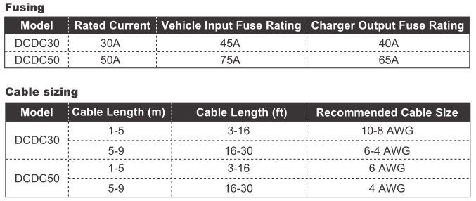
Cable and Fuse Sizing
 Operation
 Operation
LED Indicators
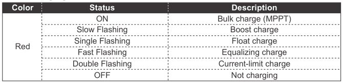
Solar Charging Indicator
Service Battery Indicator
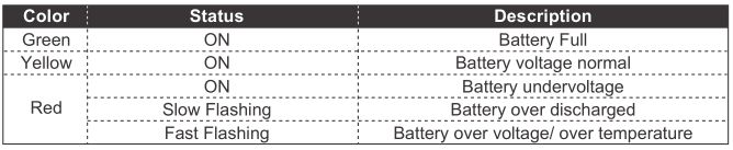
NOTEThe Charging Indicator may change under the following conditions:
- Red to Yellow: When the voltage reaches 12.2V under voltage recovery
- Yellow to Red: When the voltage drops to 12.0V under voltage warning
- Yellow to Green: A. When it reaches constant voltage charging state, the charging current is smaller than 3A, lasts for 30 seconds; B. When the charging current is higher than 3A, it keeps charging until it reaches constant voltage state and the current drops below 3A, lasts 30 seconds.
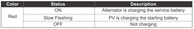
Alternator/Charging Indicator
Battery Type Indicator

NOTEUser mode is an extra feature accessed via App or Monitoring Screen; Future Development
Charging Logic
Alternator Input
1. Connect alternator with starting battery and service battery (No solar panel, or night time)
1.1 The DCDC battery charger will connect or disconnect the service battery according to the starting battery voltage.
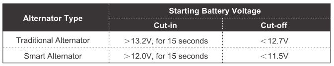
1.2 The DCDC will stop charging if the alternator input voltage is higher than 16.5V, and recover to charge when the voltage is lower than 15.5V
1.3 The maximum alternator charging for the DCDC30 is 30A and the DCDC50 is 50A.
Solar Panel Input
2. Connect solar panel, starting battery and service battery (Engine not running)
2.1 The solar input charges the service battery as priority. If the service battery voltage is lower than the boost voltage setting, solar panel will only charge the service battery.
2.2 If the service battery is in float charge stage, the starting battery will be charged at the same time. The charging voltage is limited at 13.8V. The charging amperage is limited at 25A.
2.3 After charging the starting battery for 1 minute, it will disconnect for 30 seconds and check the starting battery voltage. It will continue to charge starting battery if the voltage is lower than 12.7V and will stop charging if the voltage is higher than 13.2V.
2.4 Solar charging will be triggered if the PV input voltage is higher than 15V for 10 seconds.
2.5 The DCDC will stop charging if the PV input voltage is higher than 25.5V, and recover to charge when the voltage is lower than 24.5V.
2.6 The maximum solar charging for the DCDC30 is 30A and the DCDC50 is 50A.
Dual Input (Alternator/Solar)
3. Connect solar panel, alternator with starting battery and service battery.
3.1 The DCDC will always take as much power from the solar panel as it can before supplementing that power from alternator input, up to the rated charging current.
3.2 If the solar input power is able to keep the service battery at constant voltage charge stage, alternator wouldn’t charge the service battery.
3.3 If the MPPT charging current from solar input is not able to keep the service battery at constant voltage charge stage, alternator will cut in to charge the service battery. In this case, the maximum dual input charging will be limited to 50% from each source.
a. DCDC30: 15A from alternator, up to 15A from solar for a total of up to 30A.b. DCDC50: 25A from alternator, up to 25A from solar for a total of up to 50A.
4. Operating Temperature
4.1 The DCDC will lower the output power when its internal temperature is in the range from 65¥ to 80¥. It will stop charging when the temperature is higher than 80¥, and recover to charge when the temperature is lower than 60¥.
4.2 If the service battery type is set to lead-acid, the DCDC will stop charging the service battery when its temperature is lower than -36¥, and recover to charge when it’s higher than -34¥
4.3 If the service battery type is set to lithium, the DCDC will stop charging the service battery when its temperature is lower than 1¥, and recover to charge when it’s higher than 3¥.
Solar Charge Algorithm
MPPT TechnologyThe DCDC utilizes Maximum Power Point Tracking technology to extract maximum power from the solar module(s). The tracking algorithm is fully automatic and does not require user adjustment. MPPT technology will track the array’s maximum power point voltage (Vmp) as it varies with weather conditions, ensuring that the maximum power is harvested from the array throughout the course of the day.
Current BoostIn many cases, the MPPT charger will “boost” up the current in the solar system. The current does not come out of thin air. Instead, the power generated in the solar panels is the same power that is transmitted into the battery bank. Power is the product of Voltage (V) x Amperage (A). Therefore, assuming 100% efficiency:
Power In = Power OutVolts In · Amps In = Volts out· Amps out
Although MPPT chargers are not 100% efficient, they are very close at about 92-95% efficient. Therefore, when the user has a solar system whose Vmp is greater than the battery bank voltage, then that potential difference is proportional to the current boost. The voltage generated at the solar module needs to be stepped down to a rate that could charge the battery in a stable fashion by which the amperage is boosted accordingly to the drop. It is entirely possible to have a solar module generate 8 amps going into the charger and likewise have the charger send 10 amps to the battery bank. This is the essence of the MPPT chargers and their advantage over traditional chargers. In traditional chargers, that stepped down voltage amount is wasted because the charger algorithm can only dissipate it as heat. The following demonstrates a graphical point regarding the output of MPPT technology.
Limiting EffectivenessTemperature is a huge enemy of solar modules. As the environmental temperature increases, the operating voltage (Vmp) is reduced and limits the power generation of the solar module. Despite the effectiveness of MPPT technology, the charging algorithm will possibly not have much to work with and therefore there is an inevitable decrease in performance. In this scenario, it would be preferred to have modules with higher nominal voltage, so that despite the drop in performance of the panel, the battery is still receiving a current boost because of the proportional drop in module voltage.
Four Charging StagesThe DCDC MPPT charge controller has a 4-stage battery charging algorithm for a rapid, efficient, and safe battery charging. They include: Bulk Charge, Boost Charge, Float Charge, and Equalization.

Bulk Charge: This algorithm is used for day to day charging. It uses 100% of available solar power to recharge the battery and is equivalent to constant current. In this stage the battery voltage has not yet reached constant voltage (Equalize or Boost), the charger operates in constant current mode, delivering its maximum current to the batteries (MPPT Charging).
Constant Charging: When the battery reaches the constant voltage set point, the charger will start to operate in constant charging mode, where it is no longer MPPT charging. The current will drop gradually. This has two stages, equalize and boost, and they are not carried out constantly in a full charge process to avoid too much gas precipitation or overheating of the battery.
- Boost Charge: Boost stage maintains a charge for 2 hours by default.
Float Charge: After the constant voltage stage, the charger will reduce the battery voltage to a float voltage set point. Once the battery is fully charged, there will be no more chemical reactions and all the charge current would turn into heat or gas. Because of this, the charger will reduce the voltage charge to smaller quantity, while lightly charging the battery. The purpose for this is to offset the power consumption while maintaining a full battery storage capacity. In the event that a load drawn from the battery exceeds the charge current, the charger will no longer be able to maintain the battery to a Float set point and the charger will end the float charge stage and refer back to bulk charging.
Equalization: Is carried out every 28 days of the month. It is intentional overcharging of the battery for a controlled period of time. Certain types of batteries benefit from periodic equalizing charge, which can stir the electrolyte, balance battery voltage and complete chemical reaction. Equalizing charge increases the battery voltage, higher than the standard complement voltage, which gasifies the battery electrolyte.
WARNINGOver-charging and excessive gas precipitation may damage the battery plates and activate material shedding on them. Too high of equalizing charge or for too long may cause damage. Please carefully review the specific requirements of the battery used in the system.
Four Charging StagesThe charger has a reactivation feature to awaken a sleeping lithium battery. The protection circuit of lithium battery will typically turn the battery off and make it unusable if over-discharged. This can happen when storing a lithium battery pack in a discharged state for any length of time as self-discharge would gradually deplete the remaining charge. Without the wake-up feature to reactivate and recharge batteries, these batteries would become unserviceable and the packs would be discarded. The charger will apply a small charge current to activate the protection circuit and if a correct cell voltage can be reached, it starts a normal charge.
Lithium Battery ActivationThe charge controller has a reactivation feature to awaken a sleeping lithium battery. The protection circuit of lithium battery will typically turn the battery off and make it unusable if over-discharged. This can happen when storing a lithium battery pack in a discharged state for any length of time as self-discharge would gradually deplete the remaining charge. Without the wake-up feature to reactivate and recharge batteries, these batteries would become unserviceable and the packs would be discarded. The charge controller will apply a small charge current to activate the protection circuit and if a correct cell voltage can be reached, it starts a normal charge.
Troubleshooting
CAUTIONDo not open the device. You risk exposing yourself to an electric shock by doing this.
NOTEIf you have detailed questions about the battery charger, please contact our customer support (addresses on the back of the instruction manual).

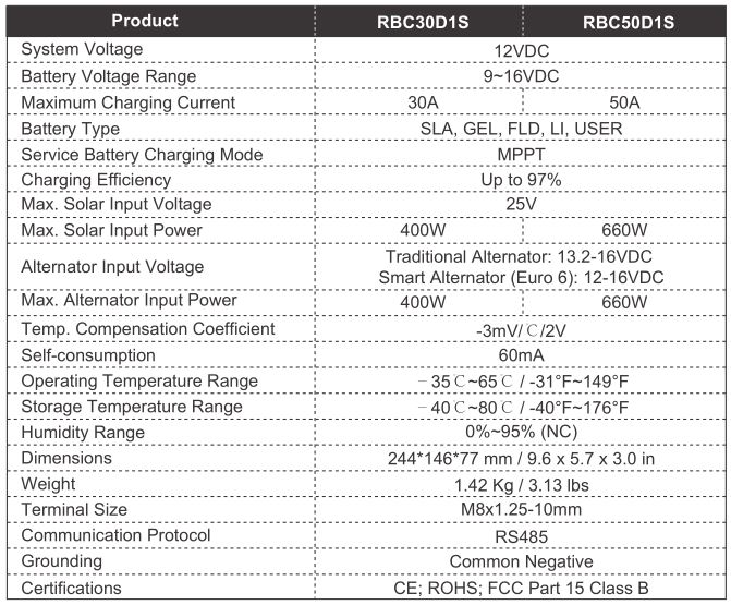
Technical Specification
Battery Charging Parameters
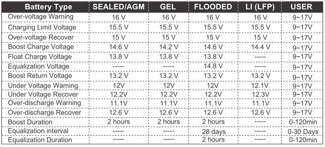
NOTEUser mode is an extra feature accessed via App or Monitoring Screen; Future Development
This equipment has been tested and found to comply with the limits for a class B digital device, pursuant to part 15 of the FCC Rules. These limits are designed to provide reasonable protection against harmful interference in a residential installation. This equipment generates, uses and can radiate radio frequency energy and if not installed and used in accordance with the instructions, may cause harmful interference to radio communications. However, there is no guarantee that interference will not occur in a particular installation. If this equipment does cause harmful interference to radio or television reception, which can be determined by turning the equipment off and on, the user is encouraged to try to correct the interference by one or more of the following measures:
- Reorient or relocate the receiving antenna.
- Increase the separation between the equipment and receiver.
- Connect the equipment into an outlet on a circuit different from that to which the receiver is connected.
- Consult the dealer or an experienced radio/TV technician for help.
This device complies with Part 15 of the FCC Rules. Operation is subject to the following two conditions: (1) this device may not cause harmful interference, and (2) this device must accept any interference received, including interference that may cause undesired operation.
![]()
RENOGY.COMRenogy reserves the right to change the contents of this manual without notice.
US
2775 E Philadelphia St, Ontario, CA 91761, USA909-287-7111www.renogy.com[email protected]
CN
15-4 400-6636-695https://www.renogy.cn[email protected]
JP
https://www.renogy.jp[email protected]
CA
https://ca.renogy.com[email protected]
AU
https://au.renogy.com[email protected]
UK
https://uk.renogy.com[email protected]
DE
https://de.renogy.com[email protected]
References
High Quality Solar Products | Renogy UK
ç¬ç«å太é½å çºé»ã·ã¹ãã å°é | RENOGY JAPANãªã³ã©ã¤ã³ã·ã§ãã
Renogy® Official- offer all off grid solar system products
Renogy black friday Bis Zu 30% Sparen| Renogy DE
RENOGY如果新能源 | 让每个人拥有独立清洁的能源
Renogy® Canada-Solar Off-grid Products
Solar Power Kits & Equipment for Sale | Renogy Australia
Renogy® Official- offer all off grid solar system products
[xyz-ips snippet=”download-snippet”]