resideo 5800PIR-OD2 Wireless Outdoor Motion Detector Installation Guide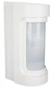
General Information
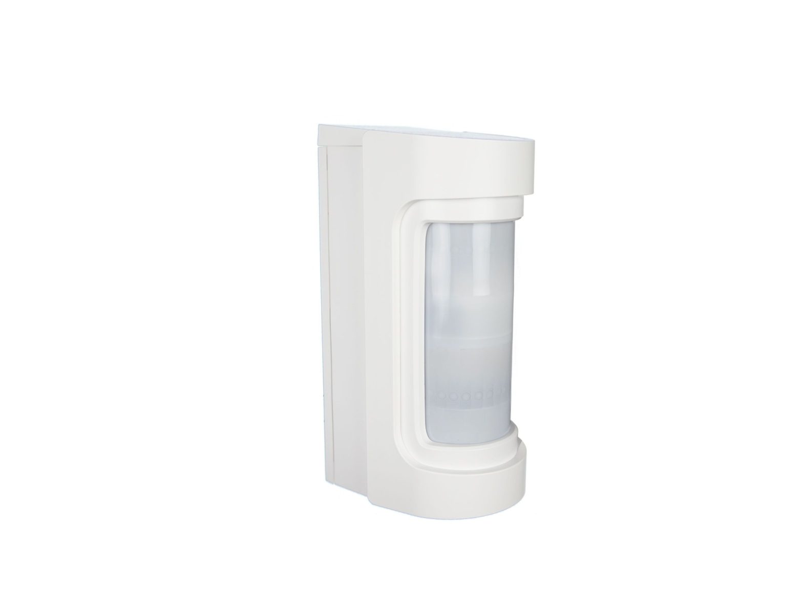
The 5800PIR-OD2 Wireless Outdoor Motion Sensor combines the convenience of wireless technology with a full featured outdoor PIR motion sensor. It has an adjustable range of up to 40ft with 7 selectable horizontal settings to cover a desired area within 180 degrees of its mounting location. It features white light immunity from low sunlight, headlights and other bright light sources. This detector can discriminate between people and small animals. It also features a Transmission Lockout that uses either a 5 or 120 second period of inactivity between activations to help save battery life.
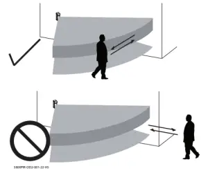
Select the Mounting Position
- Position the detector so that the intruder passes across the detection field, not into the sensor.

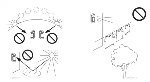
- Avoid strong sunlight into the sensor’s field.
- Avoid moving or swaying objects, trees, and bushes.
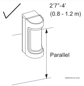
- Ensure the sensor can be mounted on a perpendicular wall or pole that would make its detection pattern parallel to the ground.
Prepare for Mounting
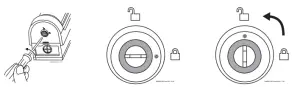
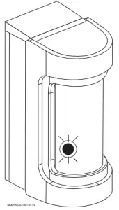
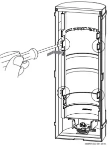
- Locate the lock on the bottom side of the motion detector.
- Use a small screwdriver to unlock the cover by turning the lock counter-clockwise until it clicks. DO NOT USE EXCESSIVE FORCE.
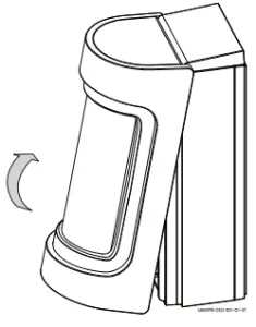
- Allow a minimum of 4.4″ (110mm) clearance above the sensor to enable opening the cover.
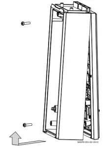
- Remove the Cover by pulling from the bottom
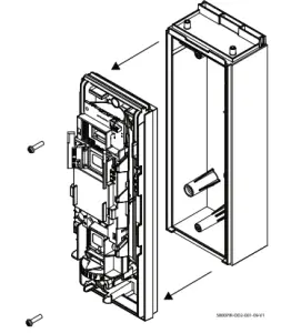
- Remove both screws from the Main PCB and pull it from the Back Box.NOTE: Use CAUTION when handling the Main PCB so components are not damaged
- Remove both screws from the Back Box and pull it from the Back Plate.
Mount the Back Plate
Wall Mount
Install the Back Plate on the wall, 2.7 – 4ft from the ground, using two 4 x 20mm screws provided.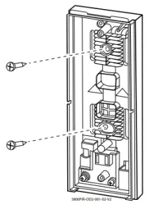
OR
Pole Mount
Using metal banding 1 inch in width, fasten the Back Plate to the pole 2.7 – 4ft from the ground.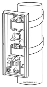
Install / Replace Batteries
Observe the proper polarity when installing and replacing the batteries. Insert the negative end of the battery first to the springs. Ensure positive side of battery is at the top, opposite side from the springs.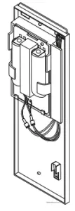
IMPORTANT:
- Use only Lithium batteries.
- Use two (2) Lithium 1.5VDC AA cells. (Energizer L91 or equivalent.)
- Change both batteries at the same time. Do not mix weak batteries with new batteries.
- Observe polarity.
Caution: 5800™ Series transmitters draw quick bursts of current during transmission, then sit idle with very nominal current draw. Most batteries are not designed for this type of use, therefore, only batteries listed as compatible should be used if the expected battery life is to be attained. Each transmitter’s Installation Instructions has listed compatible battery manufacturers and their part numbers. When other non-approved batteries are used, the quick bursts of current draw kill the battery cells prematurely causing them to go low in a matter of months and can also cause unpredictable results. Other low quality batteries have not been UL tested and pose a safety hazard if used.
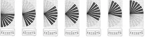
Coverage Area Angle
The coverage area will always be 90° with 13 zones, and can be adjusted to 7different angles from A to G. It comes defaulted at the D setting. Turn the PyroElectrics firmly until it clicks into the desired angle indicated by the arrows at the bottom with the respect to the letters.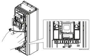
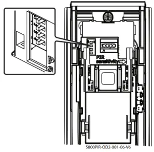
PIR Sensitivity
The sensitivity of the PIR can be adjusted from Low to Medium to High, represented as L, M, and H. The setting is on the right-hand side, behind the flange, next to the top pyro-electric.To adjust the PIR sensitivity, push the sensitivity selector up or down until it indicates L, M, or H.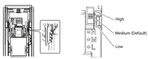
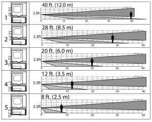
Detection Range
The detection range is determined by the bottom PyroElectric. The top Pyro Electric remains stationary and is aimed parallel to the ground. To change the detection range, simply grasp the bottom Pyro-electric and firmly move it up or down to the desired setting indicated by the embossed arrow on the bottom-left corner of the Pyro Electric. These settings are based on a mounting height of 3.3ft (1 meter). The height of the motion detector will affect the detection range. Additionally, the detection range may vary due to environment.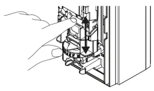
DIP Switches
There are four DIP switches that control the LED, transmitter contact input, Transmission Lockout, and Anti-Masking.
 Default values shown
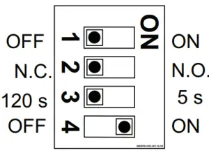
DIP 1 – LEDDIP 2 – Normally Closed or OpenDIP 3 – Transmission LockoutDIP 4 – Anti-Masking
- DIP 1 – When enabled, the red LED will always reflect the detector’s status for alarm and trouble and will illuminate through the lens. When disabled, it will only illuminate for its Warm-up period and Walk Test Mode.
- Warm-Up Period – Blinks for 60 seconds or less.
- Alarm – Lights for 2 seconds
- Mask Detection – Blinks 3 times and repeats until condition is restored.
- Blinks for 5 seconds when Walk Test expires.
- DIP 2 – Selects whether the alarm/trouble output to the transmitter will be normally open or normally closed. This needs to stay in the N.C. position (default). If it is set to N.O., the fault/restore signals for alarms/troubles may operate backwards.
- DIP 3 – Selects 120 seconds (2 minutes) or 5 seconds Transmission Lockout. This is how much time must pass from the time it was activated to when it can be activated again. This timeout option helps save battery life.
- DIP 4 – Enables or disables Anti-Masking. When enabled and it detects a masking condition it will generate a trouble.
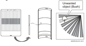
Detection Masking
Detection masking allows you to block certain parts of the lens to prevent nuisance alarms from objects such as bushes. When any part of the lens is masked, the detector will not be able to detect any movement within the masked segments.
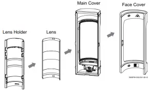
- Use a screwdriver, carefully pry on all four locking tabs to remove the lens holder.
- Identify the segments on the lens to be masked.
- Then, apply the adhesive masking strip(s) on the inside of the lens to mask the desired segments.
- Last, reassemble the lens to the lends holder and to the covers.
Program the Control Panel
The transmitter’s 7-digit serial number and loop number (Loop 1) must be programmed in the zone along with Input Type 3 (RF Supervised), and the appropriate response type for the application. Refer to the control panel’s instructions for further details on zone programming.
NOTE: The serial number and loop number can be programmed by either manually entering them in the zone program or by learning it in via wireless transmission by walking across the coverage area, activating the detector. Make sure it is not in the 5 second or 2-minute transmission lockout, else it will not activate until after the lockout time expires.
Mask Learn Mode and Walk Test
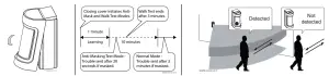
When the cover is closed, two things happen:
- The detector starts Mask Learn Mode for 1 minute with a 10 minute Anti Mask Test Mode afterwards. Learn Mode means it learns what normal objects will be within 3.3 ft (1 m) of it inside its Coverage Area so it will know the difference between a normal object and a masking object. Do NOT leave any object within 3.3ft (1 m) from the detector. During test mode, it will send a trouble after 20 seconds of being masked, whereas after test mode, it takes 3 minutes to go into trouble. It uses Active Infrared technology and constantly monitors the signal strength of the IR beam’s reflection. When the lens surface is covered by an object such as a piece of paper, the strength of the IR beam reflection increases, then, the detector initiates a trouble condition.
- Walk Test Mode is automatically enabled for 3 minutes. Walk test the detector to ensure that it will detect movement where desired and that it is operating correctly with the alarm system.
Specifications
- Detection Method: Passive Infrared
- Initial Warm Up: < 60 seconds
- Dimensions: Height: 8 in. (203mm), Width: 3.2 in. (82mm), Depth: 4.3 in. (109mm)
- Mounting Height: 2.7 – 4ft (0.8 – 1.2m) To the center of lens.
- Range: Adjustable up to 40ft (12m)
- Pattern: 90° pattern consisting of 13 zones. This pattern can be adjusted in 15° increments from center up to 45°.
- Sensitivity: 3.6° F at 2.0ft/s (2.0° C at 0.6m/s)
- Detection Speed: 1ft – 6ft 7in /s (0.3 – 2m/s)
- Operating Voltage: 3VDC (uses 2 Lithium Battery 1.5VDC AA cells) Energizer L91 or equivalent
- Transmission Lockout: Adjustable 120sec or 5sec
- Alarm Period: ~ 2 seconds
- LED Indicator: Red – Warm-up, Alarm, Masking Detection.
- Weatherproof: IP54 compliance
- Operating Temperature: – 40°F to +140°F (– 40°C to + 60°C)
- Humidity: 95% Max
- Accessories (included): Screw kit, detection masking strips.
FEDERAL COMMUNICATIONS COMMISSION (FCC) & INDUSTRY CANADA (IC) STATEMENTS
The user shall not make any changes or modifications to the equipment unless authorized by the Installation Instructions or User’s Manual.Unauthorized changes or modifications could void the user’s authority to operate the equipment.CLASS B DIGITAL DEVICE STATEMENTThis equipment has been tested and found to comply with the limits for a Class B digital device, as defined by FCC Rules Part 15.105. The Class B Digital Device statement can be viewed at:https://customer.resideo.com/en-US/support/residential/codes-and-standards/FCC15105/Pages/default.aspx
FCC / IC STATEMENTThis device complies with Part 15 of the FCC Rules, and Industry Canada’s license-exempt RSSs. Operation is subject to the following two conditions: (1) This device may not cause harmful interference, and (2) This device must accept any interference received, including interference that may cause undesired operation.
REFER TO THE INSTALLATION INSTRUCTIONS FOR THE CONTROL WITH WHICH THIS DEVICE IS USED, FOR DETAILS REGARDING LIMITATIONS OF THE ENTIRE ALARM SYSTEM.
Responsible Party / Issuer of Supplier’s Declaration of Conformity: Ademco Inc., a subsidiary of Resideo Technologies, Inc., 2 Corporate Center Drive., Melville, NY 11747, Ph: 516-577-2000
The product should not be disposed of with other household waste. Check for the nearest authorized collection centers or authorized recyclers. The correct disposal of end-of-life equipment will help prevent potential negative consequences for the environment and human health.
Any attempt to reverse-engineer this device by decoding proprietary protocols, de-compiling firmware, or any similar actions is strictly prohibited.
SUPPORT & WARRANTY INFORMATION
 report this ad
For the latest documentation and support, please go to: www.resideo.comFor the latest warranty information, please go to: www.resideo.com
References
[xyz-ips snippet=”download-snippet”]