BraukmannTKA295 Pressure-Test KitInstallation instructions
Keep instructions for later use!
Safety Guidelines
- Follow the installation instructions.
- Use the appliance• according to its intended use• in good condition• with due regard to safety and risk of danger.
- Note that the appliance is exclusively for use in the applications detailed in these installation instructions. Any other use will not be considered to comply with requirements and would invalidate the warranty.
- Please take note that any assembly, commissioning, servicing and adjustment work may only be carried out by authorized persons.
- Immediately rectify any malfunctions which may influence safety.
Description of function
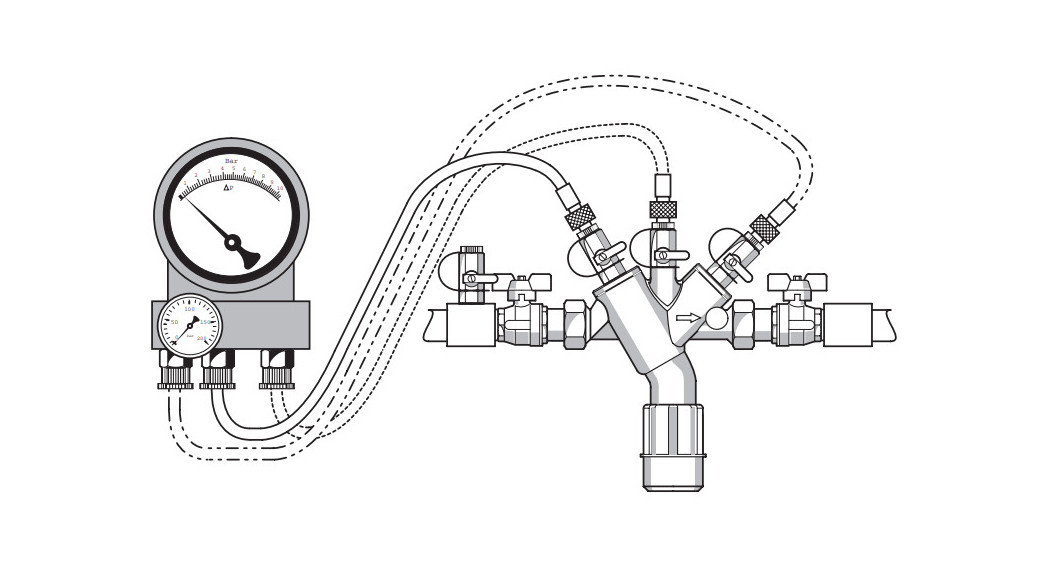
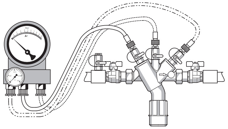
The pressure-test kit is used for inspection and maintenance by backflow preventer type BA.The pressure-test kit consists of a differential pressure gauge, needle valves, bleed valves, and different hoses. The differential pressure gauge compares the differential pressure between two chambers in the backflow preventer. The transfused pressures between the pressure chambers are adjusted and controlled by the needle valves. During the measurement procedure, the needle valves keep the pressure between the two chambers constant.The integrated filters protect the differential pressure gauge against ingress dirt particles.
Application
In combination with the following backflow preventers: BA195, BA295S, BA295I, BA295STN, BA295STN-C, BA298F, BA298IFThe pressure-test kit can only be used for the inspection and maintenance of the backflow preventer specified above. The pressure-test kit may only be used in the entire one.It is not permitted to use individual components (e.g. only differential pressure gauge) for inspection and maintenance.
Technical data
| Ambient temperature | 0-40°C |
| Operating temperature | max. 65°C |
| Operating pressure | max. 14,0 bar |
| Display range differential pressure (Δp) | 0-1,0 bar |
| Differential pressure accuracy | +/- 0,014 bar |
| Weight complete | 1,6 kg |
Scope of delivery
The pressure-test kit consists of:
| Differential pressure gauge | 1 pc. |
| Manometer, sidewise | 1 pc. |
| Hoses with a quick-release fastener, colored | 3 pc. |
| Bleed tube, clear | 1 pc. |
| Needle valves, colored | 3 pc. |
| Bleed valves, colored | 2 pc. |
| Adapter fittings | 3 pc. each |
| Carrying case | 1 pc. |
Assembly
Installations GuidelinesIt is necessary during operation to follow the operation instructions, to comply with local requirements, and to follow the codes of good practice.The note flow direction of the backflow preventer (indicated by arrow).All needle valves and bleed valves on the pressure-test kit must be closed.
- Connect a clear ventilation hose to the bleed valve (red and blue) on the top of the housing.
Inspection backflow preventer
 In accordance with DIN EN 1717, regular maintenance must be taken.
 Maintenance of the backflow preventer must be carried out by authorized personnel!Frequency: at least every six months (depending on local operating conditions Consider the operating instructions of the backflow preventer!Testing discharge valveThe backflow preventer change to shutoff position if the differential pressure between the middle- and inlet chamber falls under 0.14 bar.
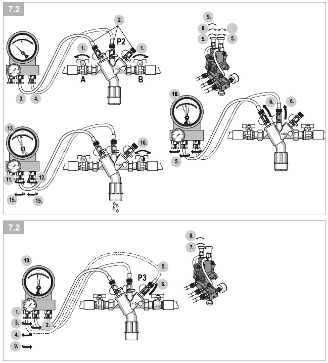
- Close shutoff valve B.
- Open shutoff valve A.• Backflow preventer is pressurized.• Water flows through the check valve.
- Install appropriate adapters in all ball valves.
- Connect hose (red) between ball valve P1 and needle valve (red) on the back of the housing.
- Connect hose (blue) between ball valve P2 and needle valve (blue) on the back of the housing.
- Close all needle and bleed valves.
- Open ball valves P1 and P2.• If possible sewage the bleed tube to a discharge or use a vent surge tank.
- Bleed the high side.• Slowly open the bleed valve (red) on top of the housing and close again when air discharge has stopped.
- Bleed the low side.• Slowly open the bleed valve (blue) on the top of the housing.
- After the differential pressure gauge reaches the upper part of the scale, close the bleed valve (blue).
- Observe the pressure drop on the differential pressure gauge.
 If the discharge valve opens the inlet check valve is faulty and has to be replaced before further testing Maintenance backflow preventer!
 - Slowly open needle valve (red) on the backside of housing for a quarter turn maximum.
- Slowly open needle valve (blue) on the backside of housing for a quarter turn maximum.
- Observe the gauge on the differential pressure gauge.• Differential pressure drops slowly to the discharge valve opening point.
- The discharge valve opens and drips.Respective opening pressure must be consulted from the operating instructions of the installed backflow preventer!The discharge valve doesn’t open close both needle valves (red and blue) on the backside of the housing continue with chapter 7.1.1!
- Close needle valves (red and blue) on the backside of housing continue with chapter 7.2.
Shutoff valve B could be faulty.
- Slowly open and close shutoff valve B again.
- Repeat steps 11 to 15 chapter 7.1.If the discharge valve still doesn’t open shutoff valve B is faulty has to be replaced before further checks!
Testing outlet check valve
- Connect hose (yellow) to the connection of needle valve (yellow) on the back of the housing and sewage the open end of the hose to a discharge.
- Slowly open the needle valve (red) on the back of the housing.
- Slowly open the needle valve (yellow) on the back of the housing.• Hose (yellow) is deaerated.
- Close the needle valve (yellow) on the back of the housing.
- Connect hose (yellow) to ball valve P3.
- Slowly open ball valve P3.
- Slowly open the bleed valve (blue) on the top of the housing.
- After the differential pressure gauge reaches the upper part of the scale, close the bleed valve (blue).
- Slowly open the needle valve (yellow) on the back of the housing.
- Observe the gauge on the differential pressure gauge.• Differential pressure doesn’t drop to discharge valve opening point. If the discharge valve doesn’t open testing is (successfully) finished.If the discharge valve opens the check valve has to be replaced before further testing Maintenance backflow preventer!
Testing inlet check valve
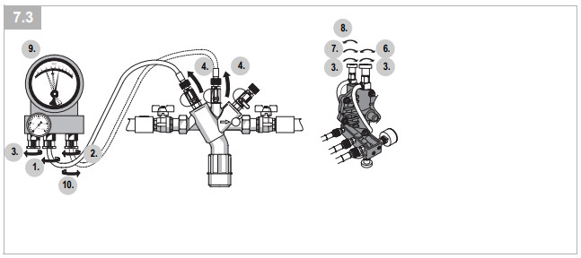
- Connect hose (red) between ball valve P1 and needle valve (red) on the back of the housing.
- Connect hose (blue) between ball valve P2 and needle valve (blue) on the back of the housing.
- Close all needle and bleed valves.
- Open ball valves P1 and P2.• If possible sewage the bleed tube to a discharge or use a vent surge tank.
- Bleed the high side.• Slowly open the bleed valve (red) on top of the housing and close again when air discharge has stopped.
- Bleed the low side.• Slowly open the bleed valve (blue) on the top of the housing.
- After the differential pressure gauge reaches the upper part of the scale, close the bleed valve (blue).
- Observe the pressure drop on the differential pressure gauge.
- Slowly open needle valve (blue). Differential pressure rises until the inlet check valve begins to open.
- Close needle valve (blue).The discharge valve mustn’t drain otherwise it is leaky and has to be replaced.The differential pressure has to stay constant otherwise the inlet check valve is leaky and has to be replaced.
- Open shutoff valves on inlet and outlet. Close ball valves.Clean and dry thoroughly pressure-test kit! Let open all needle valves and bleed valves during storage!Do not put pressure-test kit damp inside carrying case!
Maintenance
Differential pressure gaugeIf the accuracy of the differential pressure gauge is out of range( siehe chapter 4.) the differential pressure gauge must be calibrated new.Send in complete pressure-test kit on:Ademco 1 GmbHHardhofweg 4074821 Mosbach
Disposal
The pressure-test kit consists of:Red-bronze, brass, steel, plastic![]() Observe the local requirements regarding correct waste recycling/disposal!
Observe the local requirements regarding correct waste recycling/disposal!
Troubleshooting
| Disturbance | Cause | Remedy |
| No or insufficient gauge in the differential pressure gauge | Differential pressure gauge faulty | Call Technical Customer Service |
| Hoses connected incorrectly | Connect hoses correctly (consider figures) | |
| Wrong adapter fittings are installed | Install correct adapter fittings | |
| Hoses faulty | Check hoses for bends and if necessary replace | |
| Needle valves or bleed valves faulty | Check or replace needle valves or bleed valves | |
| Filters in the hoses are contaminated Or worn | Replace filter |
![]() Manufactured forand on behalf ofPittway Sàrl, Z.A., La Pièce 4,1180 Rolle, Switzerland
Manufactured forand on behalf ofPittway Sàrl, Z.A., La Pièce 4,1180 Rolle, Switzerland
For more informationhomecomfort.resideo.com/europeAdemco 1 GmbH, Hardhofweg 40,74821 MOSBACH, GERMANYPhone: +49 6261 810Fax: +49 6261 81309Subject to change. MU1H-1227GE23 R0321
© 2021 Resideo Technologies, Inc. All rights reserved.
MU1H-1227GE23 R0321
References
[xyz-ips snippet=”download-snippet”]