resideo Compact Booster Unit
Installation instructions
Compact Booster Unit – single pump
Safety Guidelines
- Follow the installation instructions.
- Use the appliance
- according to its intended use
- in good condition
- with due regard to safety and risk of danger.
- Note that the appliance is exclusively for use in the applications detailed in these installation instructions (see 4.2 Technical Data). Any other use will not be considered to comply with requirements and would invalidate the warranty.
- Please take note that any assembly, commissioning, servicing and adjustment work may only be carried out by authorized persons.
- Immediately rectify any malfunctions which may influence safety.
General comments
- The operating manual includes basic instructions for assembly, operation and maintenance. They ensure safe handling and avoids personal injuries or property damage
- Observe all safety instructions.
- Before assembly and start-up, the manual has to be read by the operator as well as by the responsible technical/operating personnel and has to be stored at the site of the compact booster unit at all times.
- This operating manual must always remain accessible at the plant.
- Instructions and markings that are directly attached to the product have to be observed and must be kept completely legible. This applies for example to:
- Arrow for flow direction
- Connection labels
- Identification plate
Intended use
The compact booster unit may only be operated in such areas as described in the other applicable documents.
- Operate the compact booster unit only if it is in perfect working condition.
- Do not operate the compact booster unit if it is only partially assembled.
- The compact booster unit may only be used to pump the medium as described in the documentation of the respective version.
- Never operate the compact booster unit without pump medium.
- Observe the values for minimum pumping rates (avoiding damage because of overheating, storage damage, …).
- Observe the values for maximum pumping rates (to avoid damage due to overheating, floating ring seal damage, cavitation damage, storage damage, …).
- Do not throttle the input of the compact booster unit (to avoid cavitation damage).
- Other modes of operations, if not mentioned in the documentation, have to be coordinated with the manufacturer.
Personnel qualification and training
- Only let specially qualified personnel perform repair and maintenance work.
- The area of responsibility and supervision of the personnel must be precisely regulated by the operator during transport, installation, operation, maintenance and inspection.
- This compact booster system may only be assembled, started, maintained, and shut down by persons who have been trained, instructed and authorized to do so.
- In some cases, training can be arranged by the manufacturer if asked by the operator.
- Training or personnel to operate system may only be conducted under the supervision of specialized technicians.
Consequences and dangers that result from not observing the manual
- Not observing this manual will lead to loss of the warranty and make damage claims invalid.
- Failure to observe the manual can lead, for example, to the following dangers:
- Hazard to persons caused by electrical, thermal, mechanical, and chemical influences
- Loss of important product functions
- Failure to perform required maintenance and service measures
- Environmental hazard caused by leakage of hazardous substances
Safety-conscious working
Besides the safety instructions presented in this manual and its intended use, the following safety regulations are valid:
- Accident prevention regulations, safety and operating regulations
- Explosion prevention and protection regulations
- Safety regulations for handling hazardous substances
- Applicable standards, regulations and laws
Safety instructions for the operator/ operating personnel
- Provide on-site protection against contact for hot, cold, and moving parts and check if they function properly.
- Do not remove the protection against contact during operation of the pump.
- Eliminate hazards caused by electrical energy (for details refer to the country specific regulations and/or local power supply companies).
- If there is no risk of the hazard potential being increased by switching off the pump, provide an emergency stop command device in the immediate vicinity of the pump / pump unit when installing the pump set.
Safety instructions for maintenance, inspections and assembly
- Alterations or modifications of the system are only permitted with the consent of the manufacturer.
- Use only original parts or parts authorized by the manufacturer.
- Use of parts other than those authorized may lead to loss of liability for any damage they may cause.
- The compact booster unit is assembled, commissioned, maintained, and shut down solely by sufficiently qualified and authorised personnel.
- The operator must ensure that the compact booster unit is maintained and assembled by sufficiently qualified and authorized personnel.
- Perform service on the system only when the machine is off.
- The pump housing has to be at ambient temperature.
- The pump housing has to be depressurized and empty.
- The procedures described in the manual for shutting down the system have to be observed under all circumstances.
- Reinstall safety equipment and protective devices and activate them again immediately after work on the system has been completed. Before starting up again, observe the start-up checklist.
- Keep unauthorized persons (e.g. children) away from the system.
- Wait at least 10 minutes before opening the compact booster unit or before removing the power voltage
The limits that are stated in the documentation have to always be complied with. The delivered system is only guaranteed to operate reliably when it is used as intended.
General information
Basic Principles
The manual is a part of the series and the versions as mentioned on the title page. The manual describes the safe and proper use in all modes of operation.The manual describes the safe and proper use in all modes of operation.The type label indicates the series and size, the most important operating data and the order number. The factory number/serial number describes the identifies the system uniquely and serves this purpose for all further business transactions.
Installation of the incomplete machine
For installation of incomplete machines, refer to the respective chapter Maintenance.
Target group
Target group for the operating instructions is technical trained personnel.
Other applicable documents
| Documents | Contents |
| Supplier documentation | Operating manuals and further documentation of auxiliary equipment and integrated machine parts |
Safety instructions in this manual
DANGER!Places with this sign signify that death, severe bodily injury or significant property damage will occur if the appropriate precautionary measures are not followed!
WARNING!Places with this sign signify that death, severe bodily injury or significant property damage may occur if the appropriate precautionary measures are not followed!
CAUTION!Places with this sign signify that small bodily injury or slight property damage may occur if the appropriate precautionary measures are not followed!
DANGER!General danger zoneIn combination with a signal, this symbol indicates danger of death or injury.
HAZARDOUS VOLTAGE!Hazardous voltageIn combination with a signal, this symbol indicates danger of injury from electrical voltage and information for protection of electrical voltage.
CAUTION!Machinery defectIn combination with the signal CAUTION, this symbol indicates danger of the machine and its functions.
Transportation and Storage
Check condition upon delivery
- Check the contents of each package for damage upon delivery.
- In the case of transport damage estimate the extent, document the damage and notify Reside immediately in writing.
Transportation
DANGER!Overturning of the compact booster unit Danger of being crushed by compact booster unit!
- Never get the system tangled in electrical lines.
- Follow the local safety regulations.
- Consider weight, balance point and suspension point
- Use only appropriate and authorized means of transportation, as crane, fork lift or hand lift.
- By using a crane, attach and transport the safety separation station as illustrated otherwise move the pallet with a forklift or pallet truck.


Fig. 1 Attaching the lifting means and transportationSelecting the adequate transportation device for the weight class.
- Remove packaging and caps in the connection openings
- Check the damage in transit.
- Transport the compact booster unit to the assembly site
- Lift the compact booster unit with a suitable lifting device from the pallet
- Sling the compact booster unit as shown.
- Lift the compact booster unit with a suitable lifting device from the pallet and dispose the pallet
- Put the compact booster unit carefully down at the installation site.
Storage/Preservation
CAUTION!Damage during storage caused by frost, humidity, dirt, UV radiation or pests Corrosion/Contamination of the compact booster unit! Protect the compact booster unit against frost, do not store outside.
CAUTION!Damp, dirty or damaged openings and junctions Leakage or damage of the compact booster unit!
- Uncover openings in the compact booster unit only during installation.
Return delivery
- Remove the power plug from the plug socket
- Rinse and clean the compact booster unit, especially for harmful, explosive, hot or other high-risk fluids.
- If pumped liquids have been transported whose residues with the humidity lead to corrosion damage or ignite in the event of oxygen contact, the compact booster unit must be additionally neutralized and blown through with anhydrous gas to dry.
- The compact booster unit must always be accompanied by a fully completed declaration of non-objection. It is imperative that you indicate any applied safety measures and decontamination measures.
Disposal
WARNING!Hazardous or hot pump medium Hazardous for humans and environment!
- Collect and dispose drilling fluid
- Wear protective clothing and mask if necessary.
- Observe the legislature concerning disposal of hazardous media.
- Remove compact booster unit.Collect grease and lubricants during disassembly
- Separate the pump materials for example according to:
- Metal
- Synthetic material
- Electronic junk
- Grease and lubricants
- Dispose according to local regulations or have them disposed of according to regulations.
Electrical appliances or electronic equipment marked with the adjacent symbol may not be disposed of with household waste at the end of its service life.To return, contact the local disposal partner.If the old electrical appliance or electronic device contains personal data, the user himself is responsible for their deletion before the devices are returned.
Description
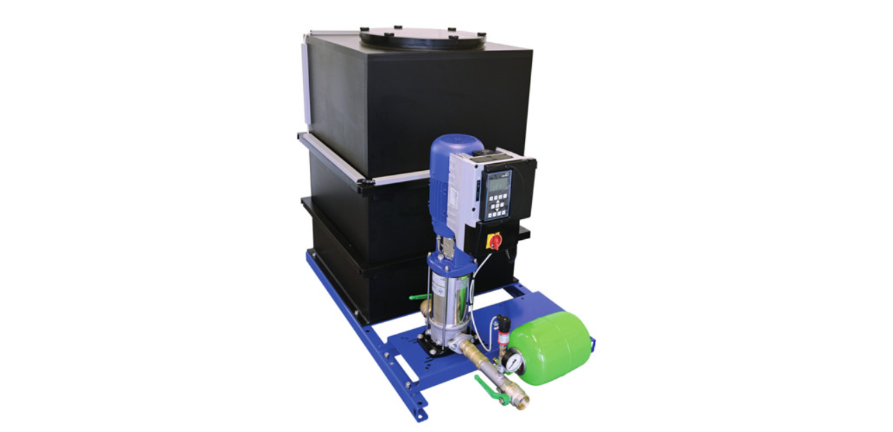
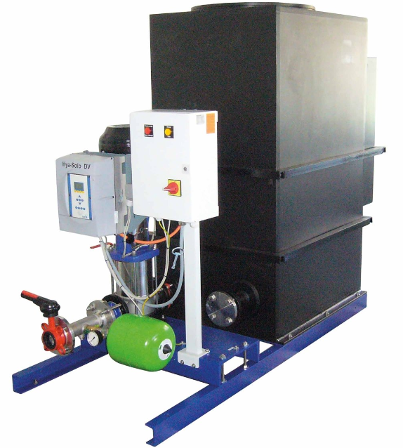
General description
Fully automatic, ready-for-connection compact booster unit consisting of a single pump unit and a buffer tank provides hygienic separation of drinking water and protects against non-drinking water of liquid category 5 according to EN 1717. Version without speed control:A fully automatic control system switches the pump unit on and off depending on pressure and switches it off depending on the flow. If the pressure falls below the preset pressure setting, the pump unit switches on and generates a constant pressure, the pump unit switches on and generates a constant pressure. With consumption decreases and the flow falls below the minimum flow rate, the pump unit switches off. The connection for dry-running protection is designed as a digital input. If the connection is open, the control unit switches off the compact booster unit after approx. 10 seconds (factory setting).Version with speed control:A fully automatic control system switches the pump unit on and off depending on the pressure. If the pressure falls below the preset pressure setting, the pump unit switches on and generates a constant pressure. As consumption decreases and the pressure falls below the set pressure, the pump unit switches off.The connection for dry-running protection is designed as a digital input. If the connection is open, the control unit switches off the compact booster unit after approx. 10 seconds (factory setting).
Technical Data
| Media | |
| Medium: | Industrial water Cooling waterLiquids which do not attack the materials chemically and mechanically.max. +30 °C |
| Flow rate: | |
| CBU142 (ON/OFF) | up to 8 m3/h, 2,22 l/s |
| CBU142FU | |
| Max. pumping head: | |
| CBU142 (ON/OFF) | 76 m |
| CBU142FU | 70 m |
| Connections/Sizes | |
| Connection sizes: | G 11/4” – R 1 1/4“ |
| Pressure values | |
| Max. operating pressure: | |
| CBU142 (ON/OFF) | 8 bar |
| CBU142FU | 6,5 bar |
| Specifications | |
| Actuator: | 1-Phase-alternating current(AC) motor |
| Supply voltage: | 230 V, 50 Hz |
| Protection class: | |
| CBU142 (ON/OFF) | IP55 |
| CBU142FU | |
| Thermal class: | F |
| Power: | 1.5 kW (PN) |
| Current consumption: | 9.0 A |
| Empty weight: | 81 kg |
| Tank volume: | 100 liter |
| Automation: | |
| CBU142 (ON/OFF) | Switching device, Pressure-dependent switching on and flow-dependent switching off |
| CBU142FU | Single-phase frequency inverter, motor-mounted, Pressure-dependent switch- on and switch-off |
Options
For Options visit homecomfort.resideo.com/Europe
Identification plate
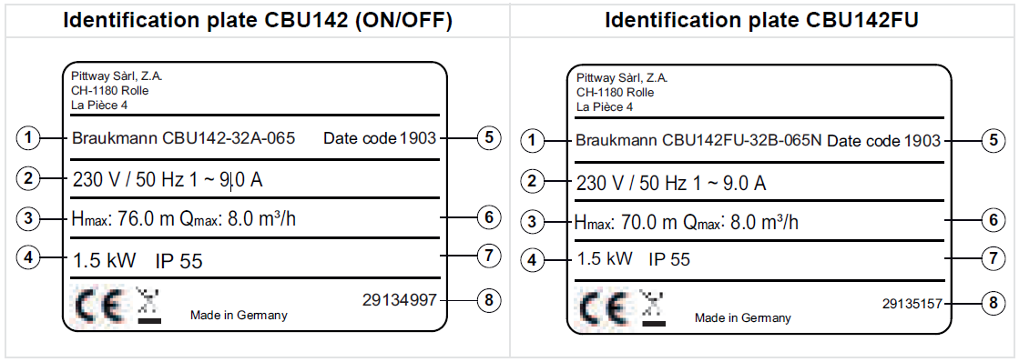
- Series, Size
- Mains voltage, current consumption
- max. pumping head
- Power consumption
- Data code
- Max. permissible flow rate
- Ingress protection rating
- Product code
Key for production number
| Item | Meaning |
| 19 | Year of production |
| 03 | Week of production |
Note:For example: 1903
Dimensions
OverviewCBU142 (ON/OFF)
Note: All dimensions in mm unless stated otherwise.
Installation Guidelines
Testing before set-up
WARNING!Installation on non-level and non-structural installation sitesPersonal and property damage!
- Ensure sufficient compressive strength according to class C12/15 for concrete in the exposition class X0 according to EN 206-1.
- Installation location has to be horizontal
- Observe the weight
NOTICESufficient noise insulation for the building is ensured due the compact booster unit`s safety store.
NOTICEDo not operate the compact booster unit near living rooms and bedrooms.
Check the following points prior to installation:
- Inspect the building architecture and prepare it according to the dimension sheet.
- According to specifications on the type label, the system is suitable for the electric supply network.
- Frost-free installation location
- Lockable installation location
- Well ventilated installation location
- A sufficiently dimensioned dewatering connection (drain connection or similar) is required (observe EN 12056).
- If available, observe the creep resistance of the compensator.
- Compensators have to be able to be easily replaced.
Installation compact buster unit
WARNING!The compact booster unit is top heavy.Danger of injury of overturning of the compact booster unit
- Secure the system so that it cannot tip over before it has been permanently anchored.
- Anchor the system securely to the foundation.
To avoid the transfer of pipeline forces and structure-borne sound to the compact booster unit, it is recommended to install compensators with a tie bar.
Packaging is removedSuitable location is selected according to specifications For service work there is sufficient space in all directions.
- Mark the installation holes on the floor as described in the data sheet.
- Drill holes (maximum Ø12 mm).
- Insert suitable, proper sized dowels.
- Position the system for installation.
- Anchor the system solidly to the foundation with adequate bolts.
Connecting pipeline
CAUTION!Airbag formation in the suction lineCompact booster unit can not suck in any medium!
- Install the pipeline rising

Fig. 2 Correct connection of the pipelineThe use of compensators with tie bars is recommended.
- Always install pipelines so that they are free of tension.
- Pipeline with discharge pressure lines with the distribution lines on the backed and discharge side.
Installation of pipeline compensator
DANGER!Sparks and radiant heat Fire hazard!
- Take appropriate measures to protect the compensator during welding work in the vicinity.
CAUTION!Leaky compensator Flooding the installation room.
- Check regularly for rips and blisters, exposed material or other defects.
The compensator is provided with a structure-borne sound insulation to intercept the length limitation to absorb any reaction forces.
- Install the compensator in the pipeline without tension.
- Fasten bolts equally cross-wise.
- Do not paint the compensator and always protect it against oil.
- The compensator has to be accessible on the compact booster unit at any time for inspection purposes and for this reason should not be included in the pipe insulation.
- The compensator is subject to wear.
HAZARDOUS VOLTAGE!Unqualified persons working on the compact booster unit
Danger to life from electric shock!
- Work on electrical equipment may only be performed by specialist electric technicians.
- Observe IEC 60364 regulations.HAZARDOUS VOLTAGE!Faulty mains connectionDamage to the electricity network, short circuit!
- Observe the conditions for technical connections of the local power supply companies.
The diameter of the electrical supply line has to be determined according to the total connection value.
Commissioning/Decommissioning
Commissioning
Start-up requirements
CAUTION!Dry running pumpDamage of the pump / Compact booster unit
- If the dry running protection is deactivated, then the operator takes responsibility in the case of dry running.
Before start-up of the compact booster unit, the following points have to be ensured:
- The compact booster unit is electrically connected to all protective devices in accordance with the regulations.
- The relevant VDE and country-specific regulations have to be adhered to and fulfilled.
Fill up and vent the compact buster unit
CAUTION!The pipeline is not free of residue Damage of the pump / Compact booster unit
- Before start-up (and testing) make sure that pipelines and compact booster unit are free of residues.The compact booster unit is hydraulically tested with water and then emptied before delivery. The whereabouts of residual water is technically unavoidable.Remove the caps of the connection openings shortly before installationBefore start-up of the compact booster unit, observe EN 806.After long service life, a rinse or professional disinfection is recommended.
For larger or widely branched piping systems, the rinsing of the compact booster unit can be done locally.
Floating ring seals may briefly show signs of leakage during start-up, but no longer after a short period of operation.
- Pipe fittings between pump and pipeline have to be tightened.
- The original operating manual of the pump is available.
- Flange connections have to be checked if they are fastened tightly.
- In and output openings for air-cooling of the motor are free.
- All shut-off valves in the system are open.
- The recharge pressure of the membrane pressure vessel is checked.
- Open the vent screws on the pump according to the original operating instructions of the pump set.
- Slowly open the shut-off valves on the input side and fill the system until pump medium runs out of every ventilation borehole.
- Close the ventilation screws, tighten pump ventilation lightly.
- Switching on the compact booster unit.
- Loosen the vent screws and allow any remaining air to escape.
- Open shut-off valve.
- Loosen the vent screws and allow any remaining air to escape.
- Tighten the vent screw.
- Check if the pump runs smoothly.
- Close the pressure-side shut-off valve and check whether the pump reaches the zero point.
- Close shut-off valvePump switches off
Switch onVersion without speed control:The compact booster unit is filled and ventilated
- Insert mains plug in the electrical socket.
Version with speed control:The compact booster unit is filled and ventilated
- Insert mains plug in the electrical socket.
- When the power supply is active, the red standby LED of the frequency inverter lights up
- When the system is ready for operation, the green SET LED of the frequency inverter flashes
- Press the Start/Stop button of the frequency inverter
- Pump unit starts, the frequency of the flashing operation LED increases
- When the operating LED is lit continuously, the setpoint is reached
Start-up checklist
| Work steps | Action | finished |
| 1 | Read operating manual. | |
| 2 | Check the voltage supply and compare with the values on the type label. | |
| 3 | Check the grounding system (by measurment). | |
| 4 | Check the mechanical connection to the water supply system. Tighten the flanges and the screws. | |
| 5 | Fill and ventilate the compact booster unit from the input side. | |
| 6 | Check the refilling. | |
| 7 | Check the switching device to see if all electrical lines are still securely plugged into the clamps. | |
| 8 | Check the preset value, correct if necessary. | |
| 9 | Check if the dry running protection is functioning. If not available, note in start-up protocol. | |
| 10 | Venting the pump a second time, after it has been running for a few minutes (5 to 10). | |
| 11 | Check the precharge pressure | |
| 12 | Fill out the start-up protocol with the operator and show the operator how the machine functions. |
Limits of operating range
DANGERSExceeding the limits Damage to the pump unit!
- Observe the operating data specified in the data sheet.
- Avoid operation against closed shut-off valve.
- Never operate the pump set outside the limits specified below.
DANGER!Risk of explosion!Exceeding the limit of use regarding to the pumped medium.
- Never pump different fluids that can chemically react with each other.
- Never pump a flammable medium with a medium temperature above the ignition temperature.
CAUTION!Excessive temperature difference between medium and pumpDamage of the machine!
- The temperature difference between medium and pump must never exceed 60 ° C.
- In cases where the temperature difference between the pump and the medium is higher than 30 ° C, slowly fill / warm the pump to avoid the risk of a temperature shock.
The operating range depends on the application and a combination of pressure and temperature.
Environmental conditionsKeep parts in their original packaging and unpack them shortly before use.The following parameters apply during transportation and storage:
| Parameter | Value |
| Environment: | clean, dry and dust free |
| Min. ambient temperature: | 0 °C |
| Max. ambient temperature: | |
| CBU142 (ON/OFF) | +40 °C |
| CBU142FU | +30 °C |
| Max. ambient relativehumidity: | 85 % * |
*non condensing
Max. operating pressure
CAUTION!Exceeding the permissible operating pressure. Damage to seals and connections!
- Do not exceed the operating pressure in the data sheet.
Pumped medium
- Industrial water
- Cooling water
- Liquids which do not attack the materials chemically and mechanically.
Decommissioning
Switch offVersion without speed control:
- Pull out the electrical mains plug
Version with speed control:
- Press the Start/Stop button of the frequency inverter
- The pump unit stops, the green operation LED disappears
- Pull out the electrical mains plug
Procedures for shutting-downThe compact booster unit is disconnected from the power supply.
- Close ball valve
- If available, connect the inlet to the tank.
- Open drain plug 1 and empty the tank.
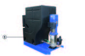
Fig. 3 Open drain plugExample CBU142
- Drain plug
Operation
CAUTION!Improper operation Damage to the pump system!
- Ensure that all local requirements are achieved, in particular the Machinery Directive and the Low-Voltage Directive.
- Check electrical wiring before start-up.
Pump control unit Version without speed control
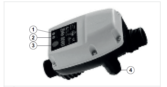
- The green light goes on to signal standby mode.
- The red light comes on in case of water shortage or malfunction.
- Reset-function
- Mains cable(Diameter 11.5 mm)
Fig. 4 Pump control unit (outside)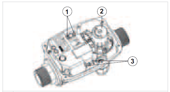
- Clamps on the motor
- Adjustment screw for recharge pressure
- Clamps on the mains cable
Fig. 5 Pump control unit (inside)
Version with speed control:An app is available for specially trained service personnel to connect to the drive is available. This app can be purchased in the Google Plays tore or iOS Pasture.
The frequency inverter is motor-mounted and self-cooling. It is equipped with the following indicators:

Fig. 6 Display
- Red standby LED Lights up when the drive is supplied with power.
- Green operation LED Flashes with varying frequency. The closer the measured pressure is to the set pressure, the higher the frequency.
- Yellow alarm LED
- Start/Stop button Starts the pump unit.
- +/- knob to adjust the pressure+/- knob in manual mode to adjust the speed of the motor.
- Green SET LEDThe drive is pre-configured at the factory.Flashes when the pump unit is ready for constant pressure mode.
Functions and features
Version without speed control Change switch-on pressureThe switch-on pressure is adjustable within a range of 2 to 3.5 bar
- Unscrew the screws of the cover with a suitable tool and remove the cover.
- Rotate adjustment screw and set the switch-on pressure to the desired value.
- Replace cover and tighten the screw hand-tight.
Reset error messagesThe red light comes on in case of water shortage or malfunction.The cause of the fault is detected and eliminated.
- Press reset button for approx. 3 seconds.
Version with speed controlThe drive is pre-configured at the factory.
| Model | VOn | max. VOff | max. IOn | max. IOff | Engine power P2 |
| V AC | V | A | A | kW | |
| MIDA 205 | 1~230 +/-15 % | 3~230 | 8 | 5 | 1,1 |
Pump unit is properly switched on
- Open the valve in the pressure line easily
- If the SET LED of the frequency inverter flashes, press the +/- button until the SET LED lights up continuously
- Press (+) to increase the switch-on pressure, press (-) to decrease the switch-on pressure
- The setting is automatically accepted after 3 seconds
Maintenance
General information/Safety regulations
HAZARDOUS VOLTAGE!Unintentionally switching on the compact booster unit
Danger to life !
- The compact booster unit has to be voltage free for all repairs and maintenance work. (Pull out the electrical mains plug)
- Secure against restart.WARNING!Inappropriate lifting/moving of heavy modules or componentsRisk of injury or property damage!
- When moving heavy modules or components, use suitable transport devices, lifting devices and lifting accessories.CAUTION!Unqualified persons working on the compact booster unitRisk of injury!
- Only let specially qualified personnel perform repair and maintenance work.CAUTION!Inappropriately maintained compact booster unit The proper function of the compact booster unit can no longer be ensured!
- Maintain the compact booster unit regularly.
- Set up a maintenance schedule for the compact booster unit that focuses especially on the pump lubrication, shaft seal and clutch.
The compact booster unit is assembled, commissioned, maintained, and shut down solely by sufficiently qualified and authorized personnel.
- Always observe the safety regulations and instructions.
- Observe the instructions for working on the pumps.
- In case of damage, please contact our service department.
- By setting up a maintenance schedule, the required maintenance to avoid expensive repairs and achieve fault-free and reliable functioning of the compact buster unit is held to a minimum.
- Avoid any use of force in connection with disassembly and assembly.
- During normal operation, no biological danger results from the compact booster unit.
- Hazards might result microbiological contamination.
- Please clean the buffer tank regularly with clean drinking water!
Monitoring Operation
CAUTION!Dry running causes increased wear Damage to the pump unit!
- Never operate the pump unit when it is empty.
- Never close the shut-off valve in the suction line and/or supply line during operation.CAUTION!Exceeding the permissible temperature for the pumped mediumDamage to the pumps!
- Operation is not permitted with closed shut-off valves over longer periods of time (overheating of pump medium).
- Observe the temperature values as stated in the data sheet and under technical data.
During operation observe and check the following points:
- Compare the recharge pressure of the membrane pressure vessel to the recommended values.
- Check the running noise of the roller bearings. Vibrations, noise, and increase in power consumption for consistent operating conditions are a sign of wear.
- If available, observe the functions of the additional connections.
Maintenance schedule
| Interval | Measure |
| Min. once a year | The pump and drive motor should run smoothly, the floating ring seals should not leak |
| Check if the shut-off, drain and check valves function properly and don`t leak. | |
| Strainer in the pressure reducing valve, if applicable | |
| Check the compensators for wear (if applicable). | |
| Check the precharge pressure and, if necessary, check if the membrane pressure vessel leaks. | |
| Check automatic switching. | |
| Check the switch-on/off points of the system. | |
| Check the water supply, recharge pressure, water shortage monitoring, and pressure reducing valve. | |
| Check if the overflow is sealed and clean. |
Set the recharge pressure
DANGER!Filling wrong gas in expansion vessel Danger of poisoning!
- Only fill the pressure pad with nitrogen.CAUTION!Recharge pressure too high Danger of damaging the tank!
- Observe the values as stated by the manufacturer of the tank (refer to type label or the tank manual).
The precharge pressure for the pressure vessel should be set to a value that is lower than the programmed switch-on pressure.Example: Precharge pressure 10% below the switch-on pressurePrecharge pressure of the membrane pressure vessel p = 0.9 x pEpE = switch-on pressure of the compact booster unit
RecommendationThese are average values. Experiments conducted on tanks have shown that the best storage volumes were achieved for pressures >3bar with a factor of 0.9 and pressures of <3bar with a factor of 0.8.
Example:pE = 5 bar: Recharge pressure 5 x 0.9 = 4.5 barpE = 2 bar: Recharge pressure 2 x 0.8 = 1.6 bar
Check the recharge pressure :
- Close shut-off valves under the membrane pressure vessel.
- Empty the membrane pressure vessel via the drain valve.
- Unscrew the protective cap of the valve on the membrane pressure vessel and store it
- Use a suitable checking device (eg tire-pressure gauge) to check the recharge pressure.
- Mount the protective cap of the valve on the membrane pressure vessel.
Fill the membrane pressure vessel
- Unscrew the protective cap of the valve on the membrane pressure vessel and store it
- Refill nitrogen via the valve.
- Mount the protective cap of the valve on the membrane pressure vessel.
Replace switching device
- Remove the power plug from the plug socket
- Pipework needs to be drained
- Close ball valve
- Loosen union not of the switching device
- Replace switching device
- Fill up pipelines
- Put power plug into the plug socket
- press reset-button on the switching device
Troubleshooting
WARNING!Improper work for troubleshooting Risk of injury!
- Observe the relevant instructions in this operating manual and / or the manufacturer’s documentation Our customer service department is at your service. Failure to comply will lead to loss of any liability claims.
| A | Compact booster unit shuts off |
| B | Pressure fluctuation on pressure side |
| C | The compact booster unit does not start. |
| D | The pump is running but doesn´t pump water. |
| E | Compact booster unit is pumping too little |
| F | Pressure on pressure side too little |
| G | Pressure on pressure side too high |
| H | Leckage of the mechanical seal |
| I | Overheating of the motor/pump. |
| J | The motor protection switch is activated. |
| K | Compact booster unit does not turn off |
| L | Compact booster unit is turning on and off too often |
| M | Overheating of the motor/pump. |
| A | B | C | D | E | F | G | H | I | J | K | L | M | Cause | Remedy |
| û | – | û | – | – | – | – | – | – | – | – | – | – | Protection against dry running is not connected | Connect or bypass |
| û | – | û | – | – | – | – | – | – | – | – | – | – | The main power supply is interrupted | Check or eliminate the defect |
| û | – | û | – | – | – | – | – | – | – | – | – | – | Control fuse has triggered | Check and replace if necessary |
| – | û | û | û | û | û | – | – | û | – | – | û | û | Shut-off valves are only opened partially or not at all | Check and open if necessary |
| – | – | – | û | û | – | – | – | û | – | û | – | û | Pump or pipeline is not completely ventilated or filled up | Venting or filling up |
| – | – | – | – | – | û | – | – | û | û | – | – | û | Pump is sluggish | Pump has to be repaired by a professional |
| – | – | – | – | – | – | – | û | – | – | – | – | – | Mechanical seal is defect | Replace mechanical seal |
| – | – | û | – | – | – | – | – | û | – | – | – | û | inlet pressure in pressure vessel is not correct | Set inlet pressure, replace
pressure bubble |
| – | – | – | – | – | – | – | – | – | – | – | û | – | System is leaky | Seal the system |
| – | – | – | û | – | – | – | – | – | û | û | – | û | check valve in compact booster unit is defect | Check and replace if necessary |
| – | – | – | û | – | û | – | – | – | – | û | û | – | Form is lower than indicated in the order data | Connect the tank |
| – | û | – | – | – | û | – | – | – | û | û | – | – | Water withdrawal is bigger than specified in the order data. | Query is necessary |
Spare Parts
For Spare Parts visit homecomfort.resideo.com/europe
Declaration of no objection
- Type
- Order number/Order item number3)
- Delivery date
- Range of Application
- Pumped medium3)
Make a check mark if applicable3):
Reasons for the return3)Notes:
The system/the accessories has to be carefully emptied and cleaned on the exterior as well as the interior.
- No special safety precautions are required for further handling.
- The following safety precautions regarding rinsing medium, residual fluids and their disposal are required:
We ensure that the above information is correct and complete and delivery will be made according to statutory requirements.
- City, date and signature
- Address
- Company stamp
Start-up protocol
The following so-called Reside Compact Booster Unit was commissioned today by the signatories, authorised Resideo customer service staff, and this protocol was written
Compact booster unit
- Series
- Size
- Serial number
- Order number
Customer/Operating site
- Customer
- Operating site
- Name
- Address
References
[xyz-ips snippet=”download-snippet”]