
![]() L6006A Aquastat® ControllerINSTALL ATION INSTRUCTIONS
L6006A Aquastat® ControllerINSTALL ATION INSTRUCTIONS
APPLICATION
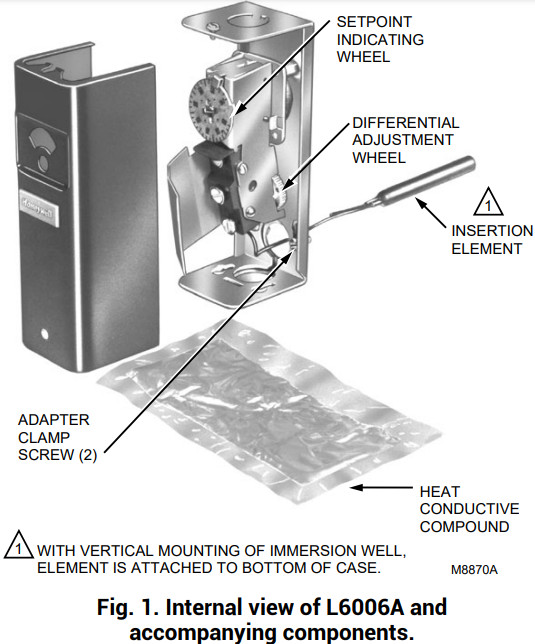
The L6006A Controller operates in response to temperature changes in hydronic heating systems. It provides spdt switching for high limit, low limit, or circulator control.The L6006A is designed for horizontal or vertical insertion/mounting using an immersion well (not included). Refer to Wells and Fittings for Temperature Controllers, form 68-0040, for part numbers and ordering information.A package of the heat-conductive compounds is included for use when the sensing bulb is inserted into a well-designed for larger bulb.NOTE: See form 69-0955, 107408, 120650 Heat Conductive Compounds Material Safety Data Sheet (MSDS) when used with this Aquastat® Controller.A 124904 Well Adapter, for use on old wells that do not fit the L6006A Immersion Well Clamp, can be ordered separately, see form 68-0040. A setting stop is factory-installed to prevent setting above 240°F (116°C) limit. The adjustable differential range is 5°F to 30°F (3°C to 17°C).
Table 1. Electrical Ratings (Amperes):
| Type | 120 Vac | 240 Vac |
| Full Load | 8 | 5. |
| Locked Rotor | 48 | 31. |
| Millivoltage | 0.25 to 0.25 to 12 Vdc |
INSTALL ATION
When Installing this Product…
- Read these instructions carefully. Failure to follow them could damage the product or cause a hazardous condition.
- Check the ratings given in the instructions and on the product to make sure the product is suitable for your application.
- The installer must be a trained, experienced service technician.
- After installation is complete, check out product operation as provided in these instructions.
![]() WARNING
WARNING
Electrical Shock Hazard.Can cause serious injury, death or equipment damage.Disconnect power supply before connecting wiring to prevent electrical shock or equipment damage.Follow instructions furnished by the system manufacturer, if available. Otherwise, refer to the following procedure.To install this L6006A as a replacement for other L6006A models:
- Shut off the power and remove the old control in the existing application. If the old immersion well appears suitable and if the adapter clamp on the L6006A Aquastat Controller fits the old immersion well spud, this immersion well does not need to be replaced.
- If the immersion well is to be replaced and if the system is filled, drain the system to a point below the boiler tapping.
- Remove plug (or old immersion well) from boiler tapping.
- Install new immersion well (not included). When a boiler tapping is greater than 1/2 in. or 3/4 in. NPT, use a reduction fitting to adapt the boiler opening to the 1/2 in. or 3/4 in. NPT threads that are standard with the well or fitting. Use thread seal compound or equivalent on the fitting.NOTE: Some models have an adjustable tubing length to 3 in. (76 mm). In these models, pull out extra tubing inside the case if needed.

- Fill the system. Make sure that the well is screwed in tightly enough to prevent leakage. Do not tighten after the controller is secured to the well, applying force to the case.
- Loosen the screw (at the top of the case, above the scale setting), and remove the cover. Loosen the two screws that secure the adapter clamp (See Fig. 1).
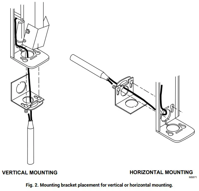
- Determine whether the vertical or horizontal mounting method is desired; see Fig. 2 for mounting bracket placement.
- Insert the sensing element into the immersion well.
- Fasten the case of the Aquastat Controller to the well with the adapter clamp. Make certain that the clamp is properly positioned over the groove of the good spud. Also, be sure the flange at the opening of the well fits snugly into the opening of the case. Be sure the sensing element bulb bottoms in the well.

Wiring
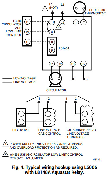
Disconnect power supply before connecting wiring to prevent electrical shock or equipment damage. Make sure all wiring complies with local electrical codes and ordinances. The case has a knockout for 1/2 in. conduit.Fig. 3 and 4 show typical wiring diagrams of Aquastat¨ Controllers used in heating systems.

OPERATION
Select-control settings according to the heating system manufacturer’s recommendations.High-limit Controller—shuts off the burner when water temperature exceeds the high-limit setting. R-B contacts make, and the burner restarts when the temperature drops to a high-limit setting minus the temperature differential.Low-limit Controller—maintains minimum water temperature for domestic hot water; e.g., tankless coil in the heating boiler. Makes R-B contacts at temperature setting minus differential.Circulator Controller—prevents circulation of water that is not hot enough. Breaks R-W contacts for circulator circuit at temperature setting minus differential; remakes the R-W contacts for the circuit when the temperature setting is reached.Switching action operates as follows:When there is a drop in water temperature (to dial setting, less differential), the R to B contacts make and the R to W contacts break, preventing circulator operation. When there is a rise in water temperature (to dial setting), R to B contacts break and R to W circulator contacts make.
ADJUSTMENT
Set the differential according to the system manufacturer’s recommendations. Rotate the wheel on the back of the snap switch until the desired reading is aligned with the V notch in the frame. The wheel provides an adjustment from 5°F to 30°F (3°C to 17°C). Replace the cover on the Aquastat Controller.Adjust the control point according to the system manufacturer’s recommendations. To adjust, insert a screwdriver in the slotted screw-type head located beneath the window in the cover. Turn the scale to the desired control point. Move the factory-set stop if desired, as shown in Fig. 5.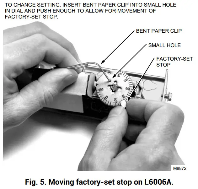 CHECKOUT
Check to make certain that the Aquastat Controller was installed and adjusted properly. Put the system into operation and observe the action of the device through several cycles to make certain that it provides proper limit and circulator control.
![]() Resideo Technologies, Inc.1985 Douglas Drive North, Golden Valley, MN 554221-800-468-150269-0235—06 M.S. Rev. 03-21 | Printed in the United States
Resideo Technologies, Inc.1985 Douglas Drive North, Golden Valley, MN 554221-800-468-150269-0235—06 M.S. Rev. 03-21 | Printed in the United States
© 2020 Resideo Technologies, Inc. All rights reserved.This product is manufactured by Resideo Technologies, Inc. and its affiliates.
[xyz-ips snippet=”download-snippet”]