
SMART OUTLETIN-WALL TAMPER-RESISTANT
Z5OUTLETZW1002Z-Wave® Certified Wireless lighting Control
|
SUPPORT |
U.S. WARRANTY |
| MyWebTechhttps://mywebtech.honeywellhome.com/ | Warrantyhttps://www.security.honeywellhome.com/hsc/resources/wa/index.html |
PARAMETERS
This Z-Wave smart outlet has advanced features that allow you to customize your experience — these features can only be adjusted by a Z-Wave enabled controller that supports the Z-Wave configuration command class.
| NUMBER | SIZE | DEFINITION | VALUE |
| 3 | 1 | Invert/Disable LED(Adjusts when theindicator LED is turnedON, OFF, or disabled) | 0 – LED ON/Device OFF1 – (Default) LEDON/Device ON2 – Disable LED |
WARNINGRISK OF FIRERISK OF ELECTRICAL SHOCKRISK OF BURNSCONTROLLING APPLIANCESCAUTION:
- DO NOT EXCEED RATINGS
- DO NOT USE TO CONTROL ANY DEVICE WHERE UNINTENDED OPERATION COULD CAUSE UNSAFE CONDITIONS (HEAT LAMP, SUN LAMP, ETC.)
- FOR INDOOR USE ONLY
NOT FOR USE WITH MEDICAL OR LIFE-SUPPORT EQUIPMENTZ-WAVE ENABLED DEVICES SHOULD NEVER BE USED TO SUPPLY POWER TO OR CONTROL THE ON/OFF STATUS OF MEDICAL OR LIFE-SUPPORT EQUIPMENT.
SPECIFICATIONS
ZW1002Power: 120VAC, 60HzSignal (frequency): 908.4/916MHzTotal maximum load for both outlets: 1800W (15A) resistiveMaximum load for Z-Wave controlled outlet: 960W incandescent, 1/2HP motor or 1800W (15A) resistiveRange: Up to 150ft. line of sight between the wireless controller and the closest Z-Wave receiver moduleOperating temperature range: 32-104° F (0-40° C)For indoor use onlySpecifications subject to change without notice due to continuing product improvement
Z-WAVE INTEROPERABILITYThis product can be included and operated in any Z-Wave network with other Z-Wave certified devices from other manufacturers and/or other applications. All non-battery-operated nodes within the network will act as repeaters regardless of vendor to increase the reliability of the network.
TOOLS
IMPORTANT!The device plugged into the Z-Wave controlled smart outlet must not exceed 960W incandescent; 1800W (15A) resistive or 1/2HP motor. The total maximum rating for both outlets combined is 1800W (15A) resistive load.
FEATURES
- One Z-Wave controlled outlet
- One always-on outlet
- Remote ON/OFF control via the Z-Wave controller/network
- Manual ON/OFF control with the manual/program button
- Blue LED indicates outlet location in a dark room
| A. Line (Hot)B. NeutralC. Ground | D. Always-on outletE. Manual/program buttonF. Z-Wave controlled outlet |
AVAILABLE CONFIGURATION PARAMETERSLED lightParameter No.: 3Length = 1 bytePossible values = 0, 1 (default) or 2Value descriptions
0 – LED ON when the load is OFF, LED OFF when the load is ON1 – LED ON when the load is ON, LED OFF when the load is OFF2 – LED always OFF
MANUAL LED INVERT METHOD
- Pair devise with a Z-Wave certified controller (section 4).
- Quickly press the ON/OFF button 10 times. The LED will invert if done correctly.
INSTALLATION
 |
 |
WARNING — SHOCK HAZARDTurn OFF the power to the branch circuit for the outlet at the service panel. All wiring connections must be made with the POWER OFF to avoid personal injury and/or damage to the outlet. This device is intended for installation in accordance with the National Electric Code and local regulations in the United States or the Canadian Electrical Code and local regulations in Canada. If you are unsure or uncomfortable about performing this installation, consult a qualified electrician.WIRING
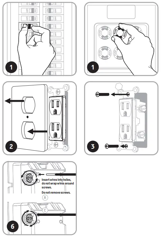
- Shut off power to the circuit at the circuit breaker or fuse box.IMPORTANT! Verify power is OFF to the electrical box before continuing.
- Remove wallplate.
- Remove the switch mounting screws.
- Carefully remove the outlet from the wall box.
- Disconnect the wires from the existing outlet. Label wires according to the previous terminal connection.
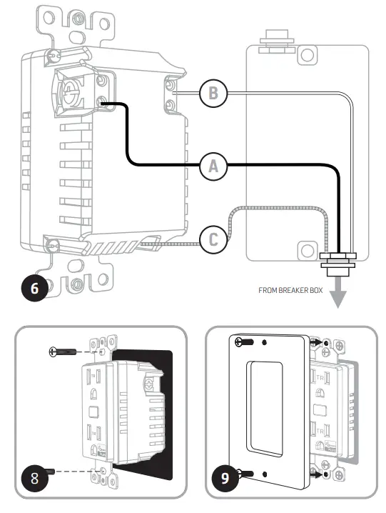
- There are three screw terminals on the Z-Wave smart outlet.These are marked:A. LINE (Hot) — Black (connected to power)B. NEUTRAL — WhiteC. GROUND — Green/BareMatch these screw terminals to the wires connected to the existing outlet.OBSERVE IMPORTANT WIRING INFORMATIONWIRE STRIP LENGTHAlways follow the recommended wire strip length (5/8in./16mm) and wiring combination when making wiring connections. Consult an electrician with questions or for professional installation.Insert wires into holes, do not wrap wires around screws.Do not remove screws.UL specifies the tightening torque for the screws is 14Kgf-cm (12lbf-in).IMPORTANT! This receptacle is rated for and intended to only be used with copper wire.WIRE GAUGE REQUIREMENTSUse 14AWG or larger wires suitable for at least 80° C for supplying line (hot), neutral, and ground connections.
- Insert Z-Wave outlet into the box being careful not to pinch or crush wires.
- Secure the outlet to the box using the supplied screws.
- Mount the wallplate.
- Reapply power to the circuit at the fuse box or circuit breaker and test the system.
BASIC OPERATION The connected device can be turned ON/OFF in two ways:
- Manually from the front program button.
- Remotely with a Z-Wave controller.
CONNECTION

CONNECTING YOUR DEVICE TO A Z-WAVE NETWORK
- Follow the instructions for your Z-Wave certified controller to add a device to the Z-Wave network.
- Once the controller is ready to add your device, press and release the program button. Repeat as necessary to add the smart outlet to the network.You have complete control to turn your fixture ON/OFF according to groups, scenes, schedules, and interactive automation programmed by your controller.If your Z-Wave certified controller features remote access, you can control your fixture from your mobile devices.
REMOVING AND RESETTING THE DEVICE
- Follow the instructions for your Z-Wave certified controller to remove a device from the Z-Wave network.
- Once the controller is ready to remove your device, press and release the manual/program button.
RETURNING SWITCH TO FACTORY DEFAULTSQuickly press the button three times. Then, press the button for at least three seconds. The LED will blink five times to confirm.Note: This should only be used in the event your network’s primary controller is missing or otherwise inoperable.
This device supports Association Command Class (3 Groups)
- Association Group 1 supports Lifeline, Binary Switch Report
- Association Group 2 supports Basic Set and is controlled by pressing the ON or OFF button with the local load
- Association Group 3 supports Basic Set and is controlled by double-pressing the ON or OFF button
- Each Association Group supports 5 total nodes
FCC/IC – ENThis device complies with Part 15 of the FCC and Industry Canada license-exempt RSS standards. Operation is subject to the following two conditions: (1) this device may not cause harmful interference, and (2) this device must accept any interference received, including interference that may cause undesired operation.FCC NOTE: The manufacturer is not responsible for any radio or TV interference caused by unauthorized modifications to this equipment. Such modifications could void the user’s authority to operate the equipment.NOTE: This equipment has been tested and found to comply with the limits for a Class B digital device, pursuant to Part 15 of the FCC Rules. These limits are designed to provide reasonable protection against harmful interference in a residential installation. This equipment generates, uses and can radiate radio frequency energy, and if not installed and used in accordance with the instructions, may cause harmful interference to radio communications. However, there is no guarantee interference will not occur in a particular installation. If this equipment does cause harmful interference to radio or television reception, which can be determined by turning the equipment off and on, the user is encouraged to try to correct the interference by one or more of the following measures:— Reorient or relocate the receiving antenna.— Increase the separation between the equipment and receiver.— Connect the equipment into an outlet on a circuit different to which the receiver is connected.— Consult the dealer or an experienced radio/TV technician for help.Important note: To comply with the FCC RF exposure compliance requirements, no change to the antenna or the device is permitted. Any change to the antenna or the device would result in the device exceeding the RF exposure requirements and void the user’s authority to operate the device.
Responsible Party – US Contact InformationFCC — U2ZZW1002 | IC: 6924A-ZW1002Resideo Technologies, Inc. | Model: ZW1002/394562 Corporate Center Dr. Suite 100, P.O. Box 9040, Melville, NY 11747 | 1-800-645-7492CAN ICES-3(B)/NMB-3(B)MADE IN CHINA39456 | ZW1002 | 03/06/20 v4
All brand names shown are trademarks of their respective owners.
Resideo Technologies, Inc.2 Corporate Center Dr. Suite 100P.O. Box 9040Melville, NY 11747www.security.honeywellhome.com | 1-800-645-7492
References
[xyz-ips snippet=”download-snippet”]