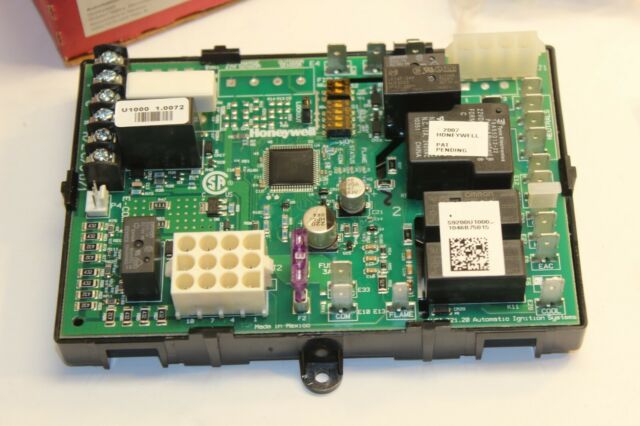
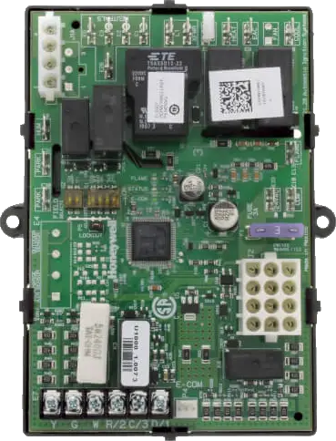
resideo S9200U1000 Universal Hot Surface Ignition Integrated Furnace Control
INSTALLATION INSTRUCTIONS
APPLICATION
The S9200U1000 Universal Integrated Furnace Control is a combustion control used in single stage gas heating and cooling appliances. Keyed wire harnesses allow the S9200U1000 to replace most furnace controls and to be applied to most heating and cooling single stage appliances.The S9200U1000 can be used with conventional thermostats as well as the EnviraCOM™ enabled VisionPRO IAQ and FocusPRO. The S9200U1000 Universal Integrated Furnace Control is intended for residential natural or liquid propane fueled furnaces only.The S9200U1000 EnvriaCOM™ communications capability allows its use in twinning applications and enables communication with local and remote diagnostic devices such as the QuickLook hand held device (QuickLook™ 72), EnviraLNK® web-based application and the W8735D Telephone Access Module (TAM).Now Available with new 12×12 pin Main Harness for Goodman/Amana/Daikin furnaces (see Table 1 and 3).
FEATURES
The S9200U1000 provides:
- Main burner ignition using a 120V hot surface igniter.
- Flame rectification circuit to monitor flame presence.
- Monitoring of system pressure switch, high temperature limit, and rollout functions.
- Appliance operation/safety requirements controlled via microprocessor.
- Control of a standard induction-type circulating fan motor (based on appliance requirements), in response to a conventional low voltage or EnviraCOM™ thermostat.
- LED system status, performance and diagnostic indication.
- Wire harnesses provided for simple replacement of most IFCs and integration with most heating and cooling appliances.
- Twinning capability.
- EnviraCOM™ communication capability to enable local and/or remote system status, diagnostics, troubleshooting, and HVAC system control.
SPECIFICATIONS
- Line Voltage: Line 120V (97-132 Vac), 60 Hz
- Low Voltage: Line 24V (19-30 Vac), 60 Hz
- Current Draw: 0.5A Input Current @24 Vac, plus valve load @ 24 Vac plus cooling contactor
- Igniter Current: 5.0A resistive @ 132 Vac output Thermostat Anticipator Setting: (Stage 1 only) 100mA Prepurge: 30 seconds
- HSI Warm-up: 17/27 or 30/30 seconds (1st/next trial) depending on DIP switch S2 setting
- Trial for Ignition: 4, 6, or 8 seconds depending on DIP switch S2 setting
- Postpurge: 15 seconds
- Inter-trial Purge: 60 seconds
- Auto Restart Delay: 60 minutes (after Soft Lockout) Ignition Trials: Three; two retries if flame is not sensed on the first trial
- Flame Failure Response Time: 2 seconds maximum @ 1μA
- LEDs: Three LEDs provide the following:
- A red LED provides system status and faults
- An amber LED provides flame status information
- A green LED provides information about the EnviraCOM traffic
- Wire Harnesses:
- 12 pin, 3 x 4 connector, 7 inches; main harness (2)
- 4-pin, 4 x 1 connector, 7 inches; igniter/inducer harness (5)
- Jumper wire
- Fan Delays:
- Heat Fan ON Delay: 30 or 60 seconds depending on DIP switch S1 setting
- Heat Fan OFF Delay: 60, 90, 120, or 180 seconds depending on Dip Switch S1 setting
- Cool Fan ON Delay: 5 seconds
- Cool Fan OFF Delay: 0 or 60 seconds (depending on DIP Switch S1 setting)
- Gas Control: Any 24 Vac redundant, direct ignition gas control rated at 1.5A or less; Resideo VR88345M4320 recommended
- Cooling Contactor: Any 24 Vac contactor rated at 1.0A or less
- Induced Draft Blower: 2.2FLA/3.5LRA maximum @ 120 Vac
- Circulator Load: 14.5FLA/25LRA maximum @ 120 Vac
- Line Voltage Humidifier: 1A resistive load maximum @ 120
- Vac Electronic Air Cleaner: 1A resistive load maximum @ 120 Vac
- Replaceable Fuse: 3.0 Amp, Automotive type
- Operating Temperature: -40 to 175°F (-40 to 79°C)
- Relative Humidity: 0% to 95% non-condensin
INSTALLATION AND CONFIGURATION OVERVIEW
The following is an overview of the steps required to install and configure the S9200U1000 Integrated Furnace Control:
- Identify cross reference target using Table 1.
- Remove old device and carefully identify and mark any wiring.
- Mount the S9200U1000 Integrated Furnace Control.
- Connect the wiring harnesses and make the wiring connections.
- Configure the field settings and safety timings.
CROSS REFERENCE
IMPORTANT
Only use the S9200U1000 on 120 Vac applications. See Table 1 for the replacement details for other manufacturers’ controls. See Table 2 for replacement details for Trane controls.
Table 1. S9200U1000 Replaces These Integrated Furnace Controls.
|
SKU |
Harness | Field Settings Recommendation – DIP Switch S1 |
Safety Timing Settings – DIP Switch S2 |
|
United Technologies |
|||
| 1012-925A | D
Main Connector C Inducer & HSI Connector |
SW1: ONSW2: OFFSW3 & SW4: 60/90/120/180 | SW1: ONSW2: ON |
| 1012-925B | |||
| 1012-925C | |||
|
Rheem/ Robert Shaw |
|||
| 62-24268-01 | D
Main Connector C Inducer & HSI Connector |
SW1: ONSW2: OFFSW3 & SW4: 60/90/120/180 | SW1: ONSW2: ON |
| 62-24268-02 | |||
| 62-24268-03 | |||
| 695-200 | |||
| Nordyne | |||
| 624557 | D
Main Connector B Inducer & HSI Connector |
SW1: ONSW2: OFFSW3 & SW4: 60/90/120/180 | SW1: ONSW2: OFF |
| 6245570 | |||
| 624557-0 | |||
| 624564 | |||
| 6245640 | |||
| 624591 | |||
| 624591A | |||
| 624591-A | |||
| 624591-B | |||
| 624591-C | |||
| 624591-D | |||
| 624628 | |||
| 624628-0 | |||
| 6246310 | |||
| 624631-0 | |||
| 624631A | |||
| 624631-A | |||
| 624631-B | |||
| 710128A | |||
| 902378 | |||
| 902696 | |||
| 903106 | |||
| CAR903106 | |||
| United Technologies | |||
| 1012-955A | D
Main Connector B Inducer & HSI Connector |
SW1: ONSW2: OFFSW3 & SW4: 60/90/120/180 | SW1: ONSW2: OFF |
| 1012955A | |||
| Texas Instruments | |||
| 6DT-1 | A
Inducer & HSI Connector |
SW1: ONSW2: OFFSW3 & SW4: 60/90/120/180 | SW1: OFFSW2: ON |
| 6DT-2 | |||
| 61F3 | |||
| York | |||
| 3101250000 | A
Inducer & HSI Connector |
SW1: ONSW2: OFFSW3 & SW4: 60/90/120/180 | SW1: OFFSW2: OFF |
| 031-00662 | |||
| 031-00662000 | SW1: OFFSW2: ON | ||
| 031-00662-000 | |||
| 031-00662-700 | |||
| 031-01140-000 | |||
| 031-01140-001 | |||
| 031011140002 | |||
| 031-01140-002 | |||
| 031-01140-701 | |||
| 031-01140-702 | |||
| 031.01234.000 | |||
| 031-01234-700 | |||
| 031-01235-000 | |||
| 031-01235-700 | |||
| 031-01250-000 | |||
| 031-01250-700 | A
Inducer & HSI Connector |
SW1: ONSW2: OFFSW3 & SW4: 60/90/120/180 | SW1: OFFSW2: OFF |
| 031-01266-000 | SW1: OFFSW2: ON | ||
| 031-01266-700 | SW1: OFFSW2: OFF | ||
| 031-01267-00 | SW1: OFFSW2: ON | ||
| 031-01267-000 | |||
| 031-01267-001 | |||
| 031-01267-001A | |||
| 031-01284-000 | |||
| 031-01933-000 | |||
| 031-01972-000 | |||
| 031-01973-000 | |||
| 031-02166-000 | |||
| 031-09166-000 | |||
| 031-09167-000 | |||
| 331-01933-000 | |||
| 331-01972-200 | |||
| 331-09167-000 | |||
| 43101972100 | |||
| 431-01972-100 | |||
| 52537074000 | SW1: OFFSW2: OFF | ||
| 52537077000 | |||
| 5253733900 | |||
| CAR33101972200 | A
Inducer & HSI Connector |
SW1: ONSW2: OFFSW3 & SW4: 60/90/120/180 | SW1: OFFSW2: ON |
| CAR03101973000 | |||
| CAR50A55843 | |||
| G951ADB1401 | |||
| G951ADB1401C | |||
| G951ADB-1401C | |||
| G951ADB1402 | |||
| G951ADB-1402 | |||
| G951AEB-1403 | |||
| P03101267001 | |||
| P031-01267-001 | |||
| PTH031011400- 00 | |||
| 031-00662 | |||
| United Technologies | |||
| 1012-83-9651B | A
Inducer & HSI Connector |
SW1: ONSW2: OFFSW3 & SW4: 60/90/120/180 | SW1: OFFSW2: O1N |
| Goodman/Amana1 | |||
| 1809913 | E
Main Connector F Inducer & HSI Connector |
SW1: ONSW2: OFFSW3 & SW4: 60/90/120/180 | SW1: OFFSW2: ON |
| B1809913 | |||
| B18099-13 | |||
| 10207701 | G
Inducer & HSI Connector |
SW1: ONSW2: OFFSW3: ONSW4: OFF | SW1: OFFSW2: ON |
| 10207702 | |||
| 10207703 | |||
| 102077-02 | SW1: ONSW2: OFFSW3 & SW4: 60/90/120/180 | SW1: OFFSW2: OFF | |
| 102077-03 | |||
| 10207704 | |||
| 102077-04 | |||
| 10207706 | |||
| 102077-09 | |||
| 10207714 | |||
| 10207719 | |||
| 102077-19 | |||
| 10207710 | SW1: ONSW2: OFFSW3: ONSW4: OFF | SW1: OFFSW2: ON | |
| PCBBF136 | 32339630-
001 12×12 Main Connector (H) 50031795- 001 4×2 Inducer & H.S.I. Connector (G) |
S1-OFFS2-OFFS3 & S4: 60/90/120/180 | SW1-SW2
Check control safety timing before setting |
| PCBBF140 | |||
| Goodman/Daikin/Amana: GMS92,GMS96 GCS92,GCS96 GMS8, GDS8, AMSS92, AMSS96, ACSS92, ACSS96, AMS8, ADSS8, DM92SS, DC92SS, DM80SS, DD80SS | |||
| PCBBF136 | 32339630-
001 12×12 Main Connector (H) 50031795- 001 4×2 Inducer & H.S.I. Connector (G) |
S1-OFFS2-OFFS3 & S4: 60/90/120/180 | SW1-SW2: Check control safety timing before setting |
| PCBBF140 | |||
| United Technologies | |||
| 1012933D | E
Main Connector F Inducer & HSI Connector |
SW1: ONSW2: OFFSW3: ONSW4: OFF | SW1: OFFSW2: ON |
| 1012-933D | |||
| 1012-83-
9336AHSC1 |
|||
| 1012-83-9337A | |||
| Texas Instruments | |||
| 41F-5 | E
Main Connector F Inducer & HSI Connector |
SW1: ONSW2: OFFSW3 & SW4: 60/90/120/180 | SW1: OFFSW2: ON |
| White Rodgers | |||
| 50T35730 | |||
| 50T35-730 | |||
| 50T35743 | |||
| 50T35-743 | |||
| ICM280 | SW1-SW4: Check control Field Settings before setting. | SW1-SW2: Check control Safety Timings before setting. | |
| White Rodgers1 | |||
| 50A50-110 | A
Inducer & HSI Connector |
SW1: ONSW2: OFFSW3 & SW4: 60/90/120/180 | SW1: OFFSW2: ON |
| 50A50-111 | |||
| 50A50-112 | |||
| 50A50-113 | |||
| 50A50-130 | SW1: OFFSW2: OFF | ||
| 50A50-131 | |||
| 50A50-142 | |||
| 50A50-143 | SW1: ONSW2: Check SettingsSW3 & SW4: 60/90/120/180 | SW1: OFFSW2: ON | |
| 50A50-205 | SW1: ONSW2: OFFSW3: ONSW4: OFF | SW1: OFFSW2: ON | |
| 50A50-206 | |||
| 50A50-207 | G
Inducer & HSI Connector |
||
| 50A50-208 | A
Inducer & HSI Connector |
SW1: ONSW2: OFFSW3 & SW4: 60/90/120/180 | SW1: OFFSW2: OFF |
| 50A50-209 | SW1: ONSW2: OFFSW3: ONSW4: ON | SW1: OFFSW2: ON | |
| 50A50-210 | SW1: ONSW2: OFFSW3 & SW4: 60/90/120/180 | SW1: OFFSW2: OFF | |
| 50A50-215 | |||
| 50A50-216 | |||
| 50A50-229 | |||
| 50A50-230 | |||
| 50A50-240 | |||
| 50A50-241 | |||
| 50A50-245 | |||
| 50A50-285 | G
Inducer & HSI Connector |
SW1: OFFSW2: OFFSW3: ONSW4: OFF | |
| 50A50-286 | A
Inducer & HSI Connector |
SW1: ONSW2: OFFSW3 & SW4: 60/90/120/180 | SW1: OFFSW2: ON |
| 50A50-288 | G
Inducer & HSI Connector |
SW1: ONSW2: OFFSW3: ON SW4: OFF | |
| 50A50-295 | |||
| 50A50-296 | SW1: ONSW2: OFFSW3 & SW4: 60/90/120/180 | ||
| 50A50-298 | SW1: OFFSW2: OFF | ||
| 50A50-407 | A
Inducer & HSI Connector |
SW1: ON SW2: OFF SW3 & SW4:
60/90/120/180 |
SW1: OFFSW2: OFF |
| 50A50-408 | SW1: OFFSW2: ON | ||
| 50A50-438 | SW1: Check SettingsSW2: ONSW3 & SW4: 60/90/120/180 | ||
| 50A50-472 | SW1: OFFSW2: OFF | ||
| 50A50-475 | SW1: ONSW2: OFFSW3 & SW4: 60/90/120/180 | ||
| 50A55-120 | SW1: OFFSW2: OFFSW3: ONSW4: OFF | ||
| 50A55-143 | SW1: ONSW2: 30/60SW3 & SW4: 60/90/120/180 | ||
| 50A55-241 | SW1: ONSW2: OFFSW3: ONSW4: ON | SW1: OFFSW2: ON | |
| 50A55-245 | SW1: ONSW2: OFFSW3 & SW4: 60/90/120/180 | SW1: OFFSW2: OFF | |
| 50A55-250 | |||
| 50A55-285 | |||
| 50A55-286 | SW1: OFFSW2: ON | ||
| 50A55-288 | G
Inducer & HSI Connector |
SW1: OFFSW2: OFF | |
| 50A55-288-05 | |||
| 50A55-843 –
universal |
A
Inducer & HSI Connector |
SW1: Check SettingsSW2: Check SettingsSW3 & SW4: 60/90/120/180 | |
| 50M56U-843
(Replace 80V Ignitors with 120V Q3200U) |
32339630-
001 12×12 Main Connector (H) 50031795- 001 4×2 Inducer & H.S.I. Connector (G) |
S1-Check SettingsS2-Check SettingsS3 & S4: 60/90/120/180 | SW1: OFFSW2: OFF |
| ICP | |||
| 1010806 | A
Inducer & HSI Connector |
SW1: ONSW2: OFFSW3 & SW4: 60/90/120/180 | SW1: OFFSW2: OFF |
| 1380686 | SW1: OFFSW2: ON | ||
| 1380698 | SW1: OFFSW2: OFF | ||
| 1380699 | |||
| 1380-686 | SW1: OFFSW2: ON | ||
| 1380-699 | |||
| Lennox | |||
| X445901 | A
Inducer & HSI Connector |
SW1: ONSW2: OFFSW3 & SW4: 60/90/120/180 | SW1: OFFSW2: OFF |
| 1214201 | SW1: ONSW2: OFFSW3: ONSW4: OFF | SW1: OFFSW2: OFF | |
| Other Manufacturers | |||
| X13120666010 | A
Inducer & HSI Connector |
SW1: ONSW2: OFFSW3 & SW4: 60/90/120/180 | SW1: OFFSW2: OFF |
| 10334901 | A
Inducer & HSI Connector |
SW1: ONSW2: OFFSW3 & SW4: 60/90/120/180 | SW1: OFFSW2: OFF |
| 350486 | |||
| 8068142 | |||
| 8068561 | |||
| 8068563 | |||
| 99958174 | |||
| 99958175 |
1- Wiring harness G should be used if the control being replaced has a 2-pin inducer/igniter connector instead of a 4-pin inducer/igniter connector.
|
SKU |
Harness | Field Settings Recommendation
– DIP Switch S1 |
Safety Timing Settings – DIP Switch S2 |
|
Trane |
|||
| CNT1309 | Add jumper on harness connector (Roll-out switch)
A Inducer & HSI Connector |
SW1: Check SettingsSW2: ONSW3 & SW4: 60/90/120/180 | SW1: OFFSW2: ON |
| CNT1616 | |||
| CNT1848 | |||
| CNT1849 | |||
| CNT2182 | |||
| CNT2183 | |||
| CNT2181 | |||
| CNT2789 | |||
| CNT03740 | SW1: ONSW2: OFFSW3 & SW4: 60/90/120/180 | SW1: OFFSW2: OFF | |
| D330927P01 | |||
| D330930P01 | SW1: OFFSW2: OFFSW3 & SW4: 60/90/120/180 | SW1: OFFSW2: ON | |
| D330934P01 | |||
| D340035P01 | |||
| D340354P01 | |||
| D340774P01 | |||
| D340790P01 | SW1: Check SettingsSW2: ONSW3 & SW4: 60/90/120/180 | SW1: OFFSW2: OFF | |
| D341122P01 | |||
| D341235P01 | SW1: ONSW2: OFFSW3: ONSW4: OFF | ||
|
White Rogers |
|||
| 50A50-571 | Add jumper on harness connector (Roll-out switch)
A Inducer & HSI Connector |
SW1: ONSW2: OFFSW3 & SW4: 60/90/120/180 | SW1: OFFSW2: OFF |
| 50A55-571 | SW1: OFFSW2: OFFSW3: ONSW4: OFF | ||
| 50A50-473 | SW1: OFFSW2: OFFSW3 & SW4: 60/90/120/180 | SW1: OFFSW2: ON | |
| 50A50-474 | |||
| 50A50-405 | |||
| 50A50-406 | |||
| 50A50-471 | |||
| 50A55-474 | SW1: OFFSW2: OFFSW3: ONSW4: OFF | SW1: OFFSW2: OFF | |
| 50A55-438 | SW1: Check SettingsSW2: OFFSW3 & SW4: 60/90/120/180 | SW1: OFFSW2: OFF |
INSTALLATION
When Installing This Product…
- Read these instructions carefully. Failure to follow them could damage the product or cause a hazardous condition.
- Check the ratings given in these instructions to make sure the integrated furnace control is suit-able for your application.
- Installer must be a trained, experienced service technician.
- After installation is complete, check out operation as provided in these instructions.
WARNINGFire or Explosion Hazard. Can cause severe injury, property damage, or death.
- The integrated furnace control can malfunction if it gets wet, leading to accumulation of explosive gas.
- Never install where water can flood, drip or condense on the control.
- Never try to use an integrated furnace control that has been wet—replace it.
- Liquefied petroleum (LP) gas is heavier than air and will not naturally vent upward.
- Do not operate electric switches, lights, or appliances until you are sure the appliance area is free of gas.
WARNINGElectrical Shock Hazard. Can cause severe injury, property damage, or death.
- Make sure to turn power off to the furnace. Failure to do this may result in electrical shock or equipment damage
- Disconnect power supply before beginning wiring or making wiring connections to prevent electrical shock or equipment damage.
CAUTIONEquipment Damage Hazard. Water can cause equipment damage or malfunction.If furnace control must be mounted near water or moisture, provide suitable waterproof enclosure.
Replacing An Existing Furnace Control
Location
In most cases the integrated furnace control is mounted on a panel within the circulator compartment of the furnace. The location must provide:
- Access to the field wiring terminals.
- Operating ambient temperatures between -40°F and 175°F (-40°C and 79°C).
- Relative humidity below 95% non-condensing.
- Protection from water, steam or corrosive chemicals that are used to clean the appliance.
- Protection from dripping water, such as from an overfilled humidifier or from condensation.
- Protection from dust or grease accumulation.
IMPORTANT
Be sure to identify the safety timings on the existing furnace control before any wires are disconnected. If this information is unavailable, check with the furnace manufacturer for recommended settings.
Replacement
To replace the existing furnace control:
- Remove the access panel to gain access to the furnace control.
- Unclip the wiring harness from the furnace control and identify/mark all wires not connected to a wiring plug.
- Once the furnace control is free from all wiring, either unclip or unscrew the furnace control from the base plate.
- Select the location within the appliance most suitable so that all existing cables or required harnesses will reach without straining either the cables or the plugs. We recommend mounting the S9200U1000 in the same location as the old furnace control, if possible. Ambient temperature at the S9200U1000 must be within the control specifications.
- The S9200U1000 can be mounted vertically in any orientation.
- Secure the board to the mounting panel base plate with the two sheet metal screws inserted through the eyelets located on the edges of the board.
- From Table 1 on page 2, identify the wiring harness(es) required for the quick installation of the S9200U1000. The provided wiring harness adapters are intended to connect to the existing wiring harness.
- Connect the appropriate end of the wiring harness to the 12-pin plug on the S9200U1000 (if required) and the other end to the existing wiring plug (previously removed from the existing furnace control). Connect the appropriate igniter/inducer harness (if required) to the 4 pin plug and the other end to either the existing plug or spade connectors (previously removed from the existing furnace control).IMPORTANT: The provided wiring harnesses are keyed. Do not force the connection if the plug on the harness and receptacle on the S9200U1000 do not easily snap closed.
- Connect the quick-connect cables to the appropriate contacts on the S9200U1000
- Set the Safety timings as required using switch S2.
- Set the field selectable timings as required using switch S1.
- Review the connections to insure no wiring is loose and there is a proper earth ground to the appliance chassis.
- Turn power ON to the appliance.
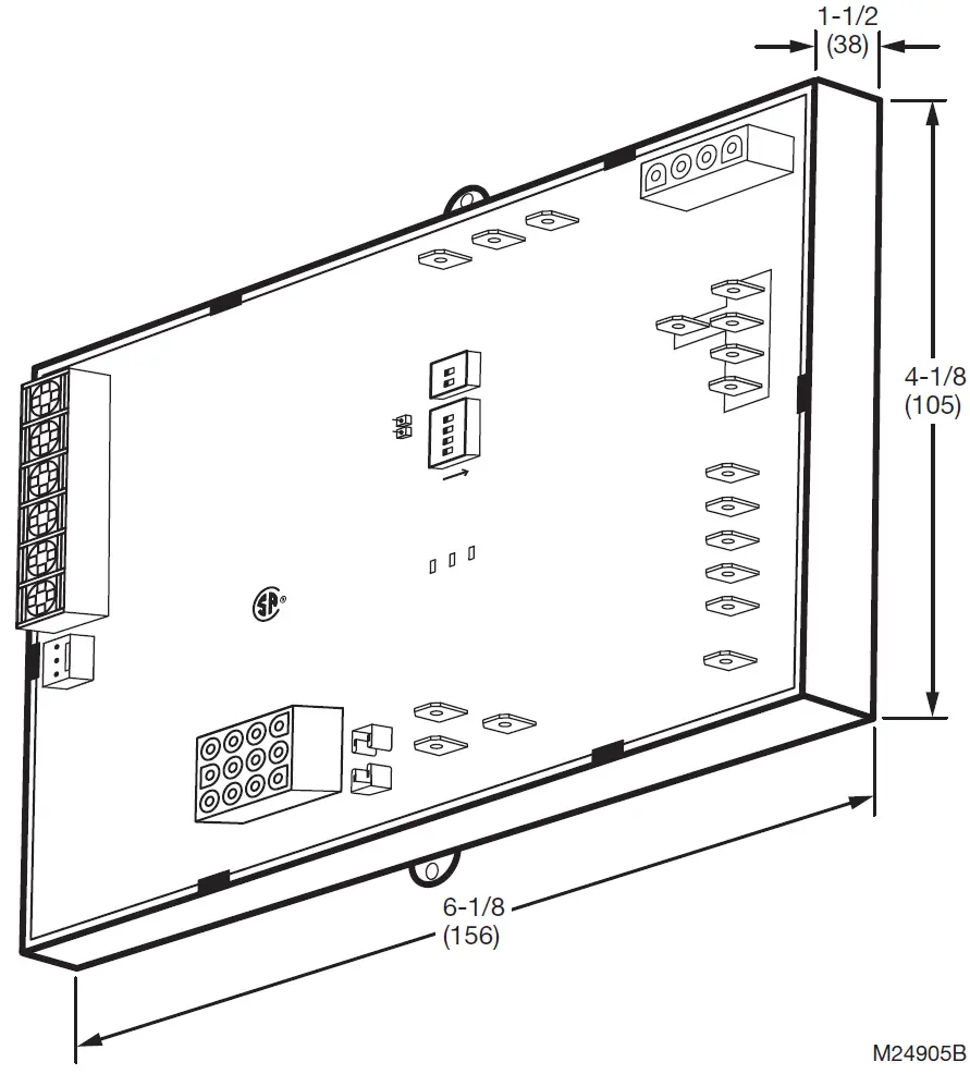
Fig. 1. S9200U1000 dimensions in inches and (mm).
Wiring
The S9200U1000 is intended to connect to the appliance with the aid of wiring harnesses. Carefully review the wiring harness selection table for the correct wiring harnesses. See Table 1 on page 2.Check the wiring diagram (Fig. 4 on page 9) and the diagram furnished by the appliance manufacturer for all terminal designations. Table 5 and Table 6 beginning on page 8 describe the wiring connections for Class 2 and Class 1 installations.Check the wiring diagrams furnished by the appliance manufacturer, if available, for circuits that differ from the general hookup shown. Carefully follow any special instructions affecting the general procedures outlined below.All wiring must comply with local codes and ordinances.See “Wiring Harnesses” for the main and igniter/inducer harness plug connections and details.
Wiring Harnesses
The following describes the main and igniter/inducer harness connections.
MAIN HARNESS PLUG CONNECTIONSThe following describes the harness plug connectors for the main harness.
IMPORTANTThe common ground required for the S9200U1000 and the main burner must be sup-plied through the plug connected to the Main Harness (12-pin connector) receptacle on the board.
Table 3. Main Harness Plug Connector 12-pin (Class 2, Low Voltage).
|
Pin # |
Function |
|
1 |
High Limit Out |
|
2 |
Flame Sense – Flame Signal Input (90 Vac, current limited) |
|
3 |
24 Vac Hot |
|
4 |
Not Used1 |
|
5 |
Rollout Switch Out |
|
6 |
24 Vac Common |
|
7 |
High Limit In + Pressure Switch Out |
|
8 |
Chassis Ground |
|
9 |
Main Valve Common |
|
10 |
Pressure Switch In |
|
11 |
Rollout Switch In |
|
12 |
Main Valve |
1 Utilize 12×12 32339640-001 Harness (H) when Furnace Harness Pressure Switch Out I/O is located on Pin 4 and not on Pin 7.
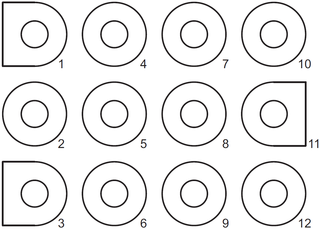
Fig. 2. S9200U1000 Main harness plug configuration.
IGNITER/INDUCER HARNESS PLUG CONNECTIONS
The following describes the harness plug connectors for the igniter/inducer.
Table 4. Igniter/Inducer Harness Plug Connector 4-pin (Class 1, Line Voltage).
|
Pin # |
Reference Lettering |
Function |
|
1 |
IND-HOT |
Inducer 120 Vac |
|
2 |
IGN-HOT |
Igniter 120 Vac |
|
3 |
IND-NEUTRAL |
Inducer Neutral |
|
4 |
IGN-NEUTRAL |
Igniter Neutral |
Fig. 3. S9200U1000 Igniter/Inducer harness plug configuration.
Wiring Connections
Table 5 describes the wiring connections for Class 2 voltages.Table 6 describes the wiring connections for Class 1 voltages.
Table 5. Wiring Connections (Class 2, Low Voltage).
|
Terminal Type |
Connection |
Connects S9200U1000 to: |
| 6-position screw terminal (#5 screw) |
D/1 (optional) |
EnviraCOM™ data connection (if used) |
|
C/3 |
24 volt ground | |
|
R/2 |
24 volt hot – Thermostat | |
|
W |
Thermostat heat input | |
|
G |
Thermostat continuous fan input | |
|
Y |
Thermostat cool input / cooling contactor output for EnviraCOM™ thermostats | |
| Polarized 3-pin connector |
E-COM |
EnviraCOM™ diagnostic or communications device |
| 12-pin connector |
Main Harness Connector |
See Table 3 on page 7 |
| Straight Spade Quick-connect |
24 Vac |
Transformer – 24 Vac |
|
COM |
Transformer – Common | |
| Fuse Block |
Fuse |
Fuse – Automotive Type – 3.0 Amps |
Table 6. Wiring Connections (Class 1, Line Voltage).
|
Terminal Type |
Connection |
Connects S9200U1000 to: |
| 4-pin connector (male terminals) |
Igniter-Inducer Harness Connector |
See Table 4 |
| Straight Spade Quick-connect |
COOL |
Circulator cool speed output |
|
EAC |
Electronic Air Cleaner 120 Vac output | |
|
HEAT |
Circulator heat speed output | |
|
CONT |
Continuous circulation | |
|
XFMR |
Transformer 120 Vac output | |
|
L1 |
Line 120 Vac hot power supply | |
|
HUM |
Humidifier 120 Vac output | |
|
PARK |
Circulator Motor Park 120 Vac input | |
|
PARK |
Circulator Motor Park 120 Vac input | |
| Straight Spade Quick-connect |
Neutrals |
Any neutral connector can be used for:
|
| Straight Spade Quick-connect |
Flame |
Flame Sense – Signal input (90 Vac, current limited) |
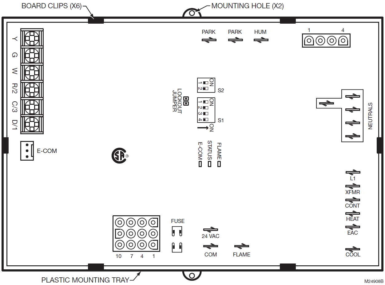
Fig. 4. Typical mounting orientation showing wiring connections and components of the S9200U1000 Universal Integrated Furnace Control.
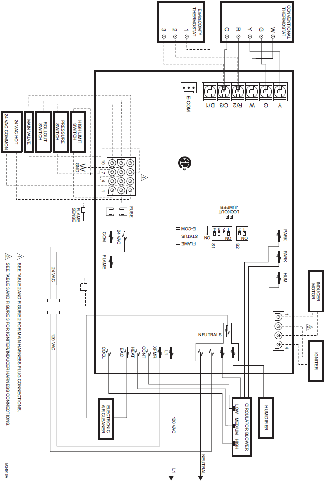
Fig. 5. Typical wiring connections for S9200U1000 Universal Integrated Furnace Control.
Safety Timing Lockout Jumper
- The S9200U1000 is equipped with a Safety Timing Lockout Jumper intended to make safety timings permanent once they are selected. To insure that resetting the Safety Timing DIP switches (Table 10 on page 12) can not cause a hazardous condition, remove the Safety Timing Lockout Jumper once the Safety Timing DIP switch position selection is made.
- In case the S9200U1000 Safety Timing Lockout Jumper is not removed after the DIP switch selection is made, the DIP switch settings will be permanently stored in the control’s non-volatile memory after the 10th full cycle each time the DIP switch is set. Once permanently stored, the Safety Timings can not be changed.
Table 7. Safety Timing Lockout Jumper.
|
Jumper |
Remove jumper to enable |
|
Lockout |
After setting the Safety Timing DIP switch (S2), remove the jumper to permanently store the settings into the non- volatile memory of the S9200U1000. |
Field Settings
The field settings can be changed whenever necessary. The change takes effect for the next situations which are being influenced by that change. If for example a particular delay is in progress and settings are changed, the current delay setting is not influenced by that change. The field settings are not considered safety critical therefore, changes to these parameters can be made at any time during and after installation.
Fixed Parameters
Fixed parameters are those settings which may not be adjusted at any time.Table 8 describes the S9200U1000 Fixed parameters.
Table 8. Fixed Parameters.
|
Fixed Parameter |
Setting |
| Pre-Purge |
30 seconds |
| Inter-trial Purge |
60 seconds |
| Postpurge |
15 seconds |
| Cool Fan ON Delay |
5 seconds |
| Ignition Retries |
2 retries (3 retries total) |
| Ignition Recycles |
3 recycles (4 cycles total) |
| Auto Restart Delay |
1 hour |
| Flame Failure Response Time |
2 seconds (maximum) |
| Fault De-bouncing Time |
2 seconds |
| Compressor Short Cycle Delay |
5 minutes |
| False Flame Recognition Period |
20 seconds |
| Heat Cycles to Safety Timings Selection Lock |
10 cycles |
DIP Switch (S1 and S2) Settings
The following field and safety parameters may be set using DIP switches S1 and S2. Refer to Fig. 4 on page 9 for the location of the two DIP switch blocks.
DIP Switch S1 – Field Settings
Table 9 and Fig. 6 describe the S1 DIP switch settings. The default factory settings are all OFF and are shown in bold.
Table 9. DIP Switch (S1) Settings – Field Settings.
|
DIP Switch S1 Descriptions |
Individual Switches |
||
|
SW1 |
SW2 |
SW3 |
SW4 |
| Cool Fan OFF Delay – 0 seconds |
OFF |
||
| Cool Fan OFF Delay – 60 seconds |
ON |
||
| Heat Fan ON Delay – 30 seconds |
OFF |
||
| Heat Fan ON Delay – 60 seconds |
ON |
||
| Heat Fan OFF Delay – 120 seconds |
OFF |
OFF |
|
| Heat Fan OFF Delay – 180 seconds |
OFF |
ON |
|
| Heat Fan OFF Delay – 90 seconds |
ON |
OFF |
|
| Heat Fan OFF Delay – 60 seconds |
ON |
ON |
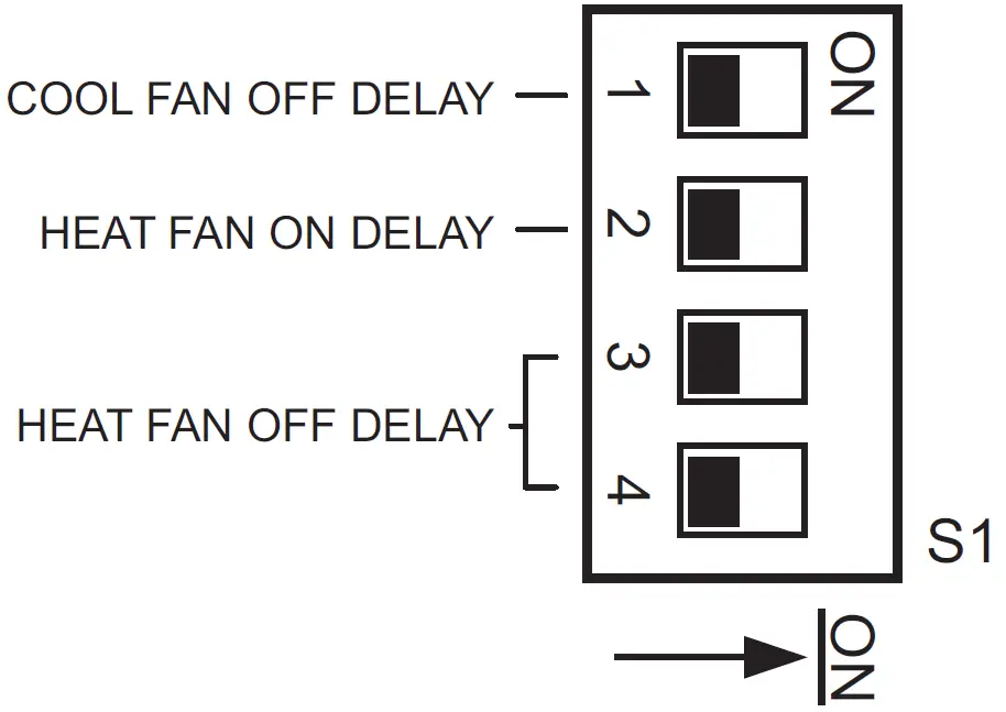
Fig. 6. DIP Switch (S1) shown with factory default settings; all OFF.
COOL FAN OFF DELAY TIMING
The Cool Fan Off Delay is the time period after the call for cooling has ended and before the deactivation of the blower motor at the cool speed. The timing is factory-set to zero (0) seconds. To change it, first disconnect the power, then set SW1 on DIP switch S1 according to Table 9.
HEAT FAN ON DELAY TIMING
The Heat Fan On Delay is the period between entering the Trial for Ignition period and the activation of the blower motor at the heat speed (if the Trial for Ignition is successful). The default factory setting is 30 seconds. To change it, first disconnect the power, then set SW2 on DIP switch S1 according to Table 9 on page 11.
HEAT FAN OFF DELAY TIMING
The Heat Fan Off Delay is the period between the loss of supervised main burner flame after the call for heat has ended and the deactivation of the blower motor at the low heat speed. The timing is factory-set to 120 seconds. To change it, first disconnect the power, then set SW3 and SW4 on DIP switch S1 according to Table 9 on page 11.
DIP Switch S2 – Safety Timings
Table 10 and Fig. 7 describe the S2 DIP switch settings. The default factory settings are all OFF and are shown in bold.
Table 10. DIP Switch (S2) Settings – Safety Timings.
|
DIP Switch S2 Descriptions |
Individual Switches |
|
|
SW1 |
SW2 |
|
HSI Igniter Warm-up Time = 17/27a seconds Trial For Ignition = 4 seconds:
This is the default setting. |
OFF |
OFF |
HSI Igniter Warm-up Time = 17/27a seconds Trial For Ignition = 6 seconds:
|
OFF |
ON |
HSI Igniter Warm-up Time = 30/30 seconds Trial For Ignition = 6 seconds:
|
ON |
OFF |
HSI Igniter Warm-up Time = 30/30 seconds Trial For Ignition = 8 seconds:
|
ON |
ON |
a The shorter of the two periods listed (17 seconds) applies to the first trial only, while the longer period (27 seconds) applies to the subsequent trials during the same call for heat.
Fig. 7. DIP Switch (S2) shown with factory default settings; all OFF.
THERMOSTAT TYPE
The S9200U1000 will accept either a conventional 24 Vac, 1-Stage Heat, 1-Stage Cool thermostat or the VisionPRO or FocusPRO EnviraCOM™ enabled thermostats.NOTE: When using a conventional 24 Vac thermostat, set the Heat Anticipator to 0.1 A.
TWINNING
EnviraCOM™ communication between two S9200U1000 controls permits the controls’ use in Twinning applications. When a second S9200U1000 is sensed on the EnviraCOM™ Bus, each S9200U1000 control proceeds into Twinning Mode. If one of the two S9200U1000 controls is removed from a Twinning application, the remaining control reverts back to standard operation only after power to the control is cycled.For twinning applications, Resideo recommends that DIP switch S1 be set to the same positions on each device so that the heat/cool fan on/off delay times are equal for both devices. Otherwise, the shorter Fan On delay and the longer Fan Off Delay times are used for both devices.
IMPORTANT
- For Twinning applications, two S9200U1000 controls must be used.
- Always power down appliances when wiring the controls in Twinning applications. Failure to do so may result in delays in the control’s registration on the EnviraCOM™ Bus.
- Fan timing changes may be detected when two appliances are Twinned.
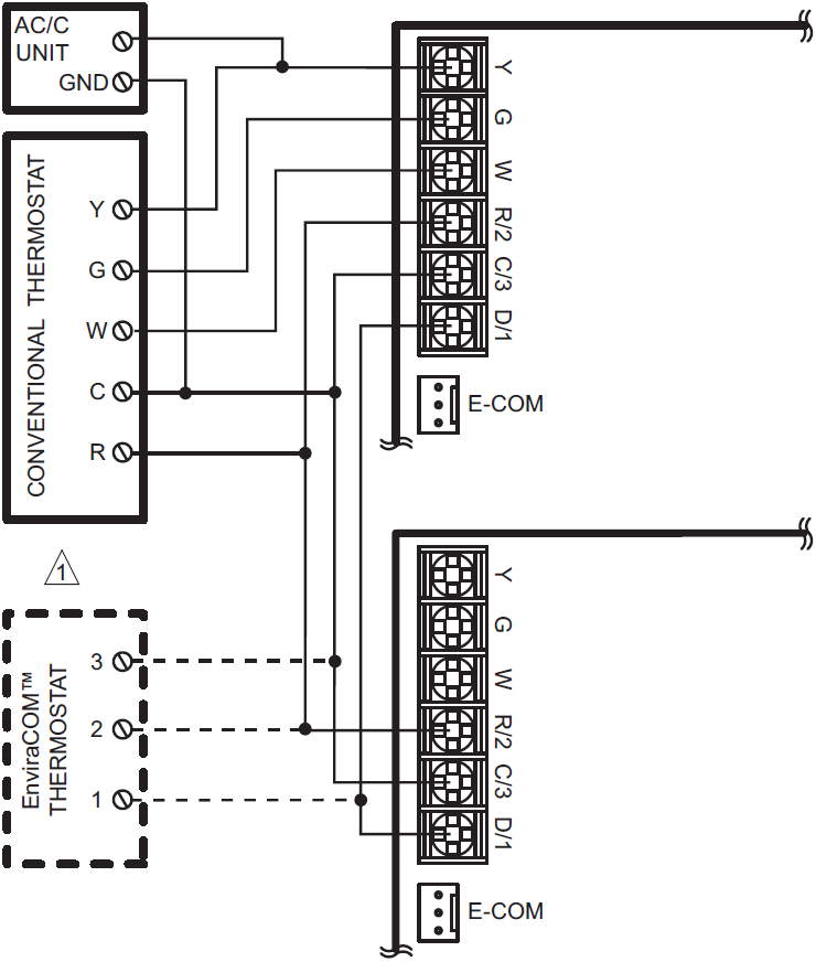
Fig. 8. Typical wiring for Twinning application.
CHECKOUT
Check out the control system:
- At initial installation of the appliance.
- As part of regular maintenance procedures.
- As the first step in troubleshooting.
- Any time work is done on the system.
LED Indicators
The S9200U1000 provides three indicating LEDs; see Fig. 4 on page 9 for location on board:
- Flame – Amber: indicates flame statusStatus – Red: indicates general system status and error codes.
- E-COM – Green: indicates EnviraCOM™ bus activity.
Use the following procedures only for the integrated furnace control; see individual component instructions for additional checkout procedures.
CHECK NORMAL OPERATION
Check Conventional 24 Vac Thermostat
- Turn on power to the appliance.
- After power is switched on, the furnace control can accept a W request after approximately 20 seconds, and Y and G requests after approximately 10 seconds.
- Set the thermostat to call for heat. Make sure the S9200U1000 control sequences the system as indicated in Fig. 9 on page 18.
- Set the thermostat below the room temperature to end the call for heat. The burner should go out; the induced draft fan should provide Postpurge time (15 seconds); and after the delay time, the indoor fan should stop.
There are three modes of operation. They are discussed in this next section in the following order:
- Normal Heat Mode
- Normal Cooling Mode
- Fan Mode
Normal Heat Mode
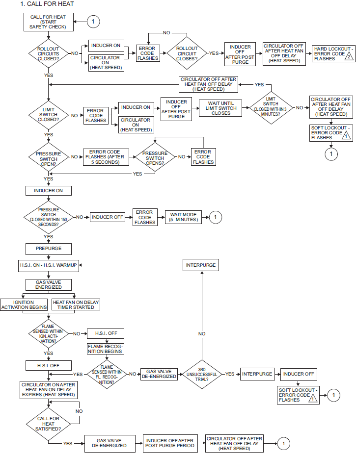
Refer to Fig. 9 on page 18 for the Heat Mode control sequence diagram. The following describes the operation during a call for heat and the heat cycle.
Call for Heat
A call for heat is signaled by the thermostat closing the contacts between R/2 and W or an EnviraCOM™ heat demand. Requests for heat are ignored if there is a call for cooling at the Y terminal.Upon a call for heat:
- The S9200U1000 conducts a safe start check that consists of an internal hardware/software self-check and verification there is no main burner flame present.
- The S9200U1000 verifies the Limit and Rollout switch circuits are closed.The S9200U1000 verifies the pressure switch circuit is open.
- The S9200U1000 energizes the inducer.
- After the Pressure Switch closes, Prepurge begins.
- After the completion of Prepurge, the HSI is energized for the Igniter Warm-up Period.
- When the Igniter Warm-up Period expires, the gas valve is energized and the Trial for Ignition begins.
- During the Ignition Activation Period, both the HSI element and the gas valve remain energized.
- After Ignition Activation, the HSI is de-energized and the gas valve remains energized for the Flame Recognition Period.
- The Heat Fan On Delay is started upon entering Trial for Ignition.
- When flame is sensed during Trial for Ignition, the S9200U1000 de-energizes the HSI and proceeds to normal run mode operation.
- Once the Heat Fan On Delay has expired, the circulator is energized on heat speed.
Call for Heat Satisfied
When the call for heat has ended:
- The gas valve is de-energized.
- The Postpurge and circulator fan off delay timings begin when the loss of flame is detected.
- The inducer is de-energized when the Postpurge Period is completed.
- The circulator is de-energized when the circulator fan off delay has expired.
Ignition RetryWhen flame is not sensed during the Trial for Ignition or is lost less than 10 seconds after exiting Trial for Ignition:
- The gas valve is de-energized.
- The inducer remains energized during the Interpurge Period.
- When the Interpurge Period expires, a new Trial for Ignition is started again for up to a maximum of two additional trials.
- After the third Trial for Ignition has failed to light the burner, the S9200U1000 proceeds to the Interpurge Period followed by the Soft Lockout, where it remains for the Auto Restart Delay before beginning another set of ignition sequences.
- The retry count is cleared if flame is sensed for longer than 10 seconds after exiting Trial for Ignition.
Ignition RecycleWhen flame is established during Trial for Ignition, maintained for at least 10 seconds, and then lost:
- The gas valve is de-energized.
- The inducer remains energized during the Interpurge Period.
- A new Trial for Ignition is started when the Interpurge Period expires.
- A maximum of three recycles are allowed on a single call for heat before the control proceeds to Soft Lockout. The recycle count is not cleared until the current demand for heat is satisfied or the S9200U1000 has just exited Soft Lockout or the S9200U1000 is in run mode continuously for one hour.
Rollout Circuit Operation (During Heat Cycle)If the rollout circuit opens during a heating cycle:
- The gas valve is immediately de-energized.
- The inducer is energized.
- The circulator is energized at heat speed.
- An LED error code is flashed, which indicates the rollout circuit has opened.
- An EnviraCOM™ alarm is active and sent on the bus.
- Thermostat requests for heat are ignored.
The S9200U1000 remains in this state until the rollout circuit closes.Once the rollout circuit has closed:
- The inducer is de-energized after the Postpurge Period.
- The circulator is de-energized after the selected heat off delay.
- The LED continues to flash the rollout switch error code.
- Thermostat requests for heat are still ignored.
The S9200U1000 remains in this state until power is cycled, at which time the S9200U1000 resumes normal operation.
Limit Switch Circuit Operation (During Heat cycle)If the limit circuit opens during a heating cycle:
- The gas valve is immediately de-energized and the inducer is de-energized after the Postpurge Period.
- The LED flashes an error code, indicating the limit circuit is open.
- An EnviraCOM™ alarm is active and sent on the bus.
- The circulator is immediately energized or remains energized at the heat speed.
- If the limit switch opens during the Trial for Ignition period, the trial is treated as a failed one (next trial is retry).
- If the limit switch opens in run mode, the sequence is treated as a failed one (next trial is recycle).
The S9200U1000 remains in this state until the limit circuit closes. Once the limit circuit closes:
- If the limit circuit was open for less than three minutes, a new ignition sequence is started and the circulator will remain energized for the selected fan off delay. If the burner is lit before expiration of the selected fan off delay, the fan off timing is stopped and the circulator remains energized.
- If the limit circuit was open for longer than three minutes, the circulator will remain energized at heat speed for the selected heat fan off delay, and the S9200U1000 will proceed to Soft Lockout, where it will remain for the Auto Restart Delay or until a thermostat reset is detected.
Pressure Switch Operation (During Heat Cycle)
- If a call for heat is initiated and the pressure switch is closed before the ignition sequence has begun, the S9200U1000 will wait five seconds and flash an LED error code, which indicates the pressure switch is stuck closed. An EnviraCOM™ alarm is active and sent on the bus. As soon as the pressure switch opens the error code clears and the ignition sequence proceeds as normal.
- If the ignition sequence has begun and the pressure switch fails to close within 150 seconds of energizing the inducer, the S9200U1000 de-energizes the inducer, starts flashing the “Pressure Switch Failed Open” error code and returns to Idle Mode for five minutes before beginning the ignition sequence again. An EnviraCOM™ alarm is active and sent on the bus.
- This process continues indefinitely and an error code indicating a failed pressure switch flashes until the pressure switch finally closes or the call for heat ends.
- If the pressure switch opens during Prepurge or Igniter Warm-up, the S9200U1000 will de-energize the igniter and leave the inducer energized for a maximum of 60 seconds to try and re-close the switch. If the switch closes, the ignition cycle will resume from the beginning of Prepurge again. If the switch does not re-close, the S9200U1000 behaves as if the pressure switch had not closed after the inducer turned on.
- If the pressure switch opens for longer than two seconds during Trial for Ignition or opens for lon-ger than 50 milliseconds during normal fire oper-ation and flame is lost, the S9200U1000 proceeds to Interpurge before attempting the ignition sequence again.An error code indicating the pressure switch failed open flashes until the burner is lit again or the heat demand is removed (see Table 12 on page 21). An EnviraCOM™ alarm is active and sent on the bus.
- If the pressure switch opens for longer than two seconds during Interpurge, the S9200U1000 proceeds to the “Wait for Pressure Switch to Close” state.
Hot Surface Igniter (HSI) ControlThe Hot Surface Igniter is directly powered by line voltage input. The HSI warm-up time is shorter for the first ignition trial when using the 17/27 second warm-up time setting and longer for subsequent trials.
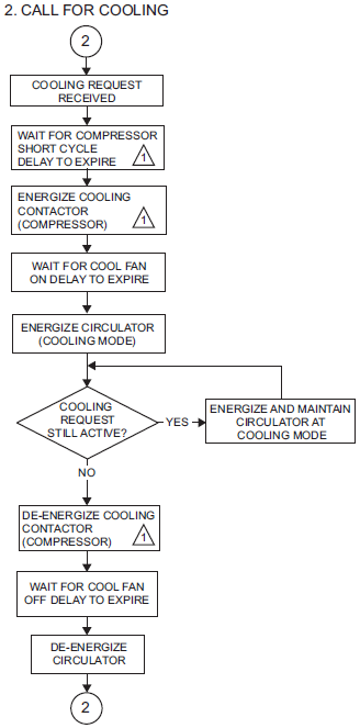
Normal Cooling Mode
A call for cooling is signaled by:
- The shorting of R/2 to Y.
- The shorting of R/2 to Y and G simultaneously.
- An EnviraCOM™ cool demand of any stage.
Refer to Fig. 10 on page 19 for the control sequence diagram.
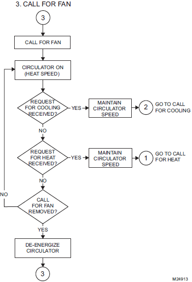
Fan Mode
In fan mode operation:
- If the S9200U1000 is not currently servicing another circulator request, the circulator energizes at the heat speed when R/2 is shorted to G and de-energizes when the request is removed. G functionality can also be received as an Envira-COM message.
- If the S9200U1000 is servicing a fan request and a call for cool occurs, the circulator switches to the cool speed after the Cool Fan On Delay.
- If the S9200U1000 is servicing a fan request and a call for heat occurs, the circulator remains energized at the heat speed.
Refer to Fig. 11 on page 19 for the control sequence diagram.
Humidity Control
The line voltage humidifier output energizes anytime the inducer energizes.Electronic Air CleanerThe line voltage EAC output energizes anytime the circulator is energized.
CHECK SAFETY SHUTOFF OPERATION
- Shut off the gas supply at the manual gas valve ahead of the appliance.
- Set the thermostat to call for heat. System should operate as indicated.
- Following lockout, open the manual gas valve and make sure no gas is flowing to the burner.
Error Conditions
The following section lists the S9200U1000 operating sequence for the stated error conditions.
Main Valve Sensing
The S9200U1000 monitors the valve output during the following conditions:
- Idle Mode
- Non-fault related states of Ignition sequence
- States related to the pressure switch fault
- When limit switch is open and inducer is no longer running, up to 180 seconds following the limit switch opening
In other conditions/states, main valve feedback is not monitored.
MAIN VALVE FEEDBACK PROCESSINGIf the inducer is off or on while the pressure switch is still open, and voltage is detected on the valve for longer than the fault debouncing time (miswire):
- All outputs are turned off except for the inducer, which is kept energized.
- The circulator energizes at the heat speed.
- If a call for cool occurs, the control energizes the circulator at cool speed after the appropriate delay.An error code flashes indicating there is a hardware malfunction.
- An EnviraCOM alarm is active and sent on the bus.
If voltage is no longer detected on the valve for more than the fault debouncing time:
- If the number of detected gas valve welded/miswire conditions have not reached 5 (since last power-up), the S9200U1000 proceeds to Soft Lockout. The S9200U1000 remains in Soft Lock-out for the Auto Restart Delay.
- If the number of detected gas valve welded/miswire conditions have reached 5 (since last power-up), the S9200U1000 enters Hard Lockout, where it remains until power reset.An EnviraCOM™ alarm indicating that manual reset is needed is active and sent on the bus.
If the inducer is energized or the pressure switch is closed and the inducer is not energized (pressure switch is stuck closed) and the main valve relay contacts are sensed closed even though the relay is not energized (welded contacts):
- An error code flashes indicating there is a hardware malfunction.
- An EnviraCOM™ alarm is active and sent on the bus.
- The inducer immediately switches off in an attempt to open the pressure switch. If, after 5 seconds, flame is sensed or voltage is still sensed on the main valve, the S9200U1000 energizes the inducer and circulator on heat speed.
If flame is not sensed and voltage on the main valve is no longer detected:
- The S9200U1000 proceeds to Soft Lockout if the number of detected gas valve welded/ miss-wire conditions have not reached 5 (since last power-up). The S9200U1000 remains in Soft Lockout for the Auto Restart Delay period. Otherwise, the S9200U1000 will enter Hard Lockout where it will remain until power is reset.
If voltage is not detected on the valve for longer than the fault debouncing time during a period when the valve is to be energized (contacts failed to make):
- the S9200U1000 proceeds as if flame is not sensed. If Soft Lockout is entered due to this condition:
- An error code flashes indicating failed hardware.
- An EnviraCOM™ alarm is active and sent on the bus.
Flame Out of Sequence
The S9200U1000 does not take action on flame sensed in Idle Mode when there is no call for heat present.If the S9200U1000 is servicing a call for heat and flame is sensed when it is not expected to be present, the ignition and fan sequences are not allowed to progress and the S9200U1000 stays in its current state. The exception is Igniter Warm-up, where the S9200U1000 proceeds to Prepurge.If the sensed flame goes away before the False Flame Recognition Period, the ignition sequence proceeds as normal.If however the sensed flame lasts longer than the False Flame Recognition Period:
- The igniter de-energizes, the inducer energizes and the circulator energizes at heat speed.
- An error code flashes indicating flame is sensed out of sequence.
- An EnviraCOM™ alarm is active and sent on the bus.
- When the sensed flame goes away, the S9200U1000 proceeds to Postpurge, followed by Idle Mode at which time the error code is cleared.
Line Voltage and Earth Ground Sensing
The line voltage circuitry is monitored for reversed polarity in Idle Mode in all non-fault related states except from HSI warm-up.
- If reversed polarity is detected for longer than the fault debouncing time, all requests for heat are ignored.
- An error code flashes indicating line voltage polarity is reversed.
- An EnviraCOM™ alarm is active and sent on the bus.
- Fan and cool requests process as normal.
Line voltage sensing requires a 120 Vac (nominal) earth ground referenced supply with an electrical connection between the transformer secondary and earth ground. Typical installations connect one side of the secondary to the appliance chassis and the appliance chassis to earth ground.
- If either the secondary to chassis connection, or the chassis to earth ground connection are missing or providing poor electrical contact, the S9200U1000 proceeds to “Self Check Lockout.”
- An error code flashes indicating there is no line voltage ground present.
- An EnviraCOM alarm is active and sent on the bus.
- Fan and cool requests process as normal..
These two faults (Line Voltage and Earth Ground Sensing) are combined into one detectable fault.
Weak Flame Sensing
The S9200U1000 flashes an error code if, after a successful Trial for Ignition and while operating in normal fire mode, the S9200U1000 senses a weak flame signal for longer than five seconds.
- When the flame is weak, the Flame (amber) LED flashes indicating there is a poor flame signal.
- An EnviraCOM™ alarm is active and sent on the bus.
To clear the error code, a strong flame must be sensed for longer than five seconds or the heat demand must be removed.
Low 24 Vac Input Sensing
If low voltage on 24 Vac input is detected, the S9200U1000 turns off all relays, ignore all requests, and wait until the voltage recovers.
- The S9200U1000 flashes an error code indicating low 24 Vac.
- An EnviraCOM™ alarm is active and sent on the bus. The alarm may not be received due to low line voltage, but will be stored in the alarm history.
Operating Sequences
Fig. 9–11 beginning on page 18 describe the operations of the S9200U1000 control.
- CALL FOR HEAT

- CALL FOR COOLING
- CALL FOR FAN
TROUBLESHOOTING
- The status codes outlined in Table 11, Table 12, and Table 13 beginning on page 20 are a general guide. Follow appliance manufacturer service instructions when available.
- Take all meter readings within the Trial for Ignition period. After the ignition period ends, before continuing, reset the system by turning down the thermostat for at least five seconds but for less than 20 seconds.
- If any component does not function properly, make sure it is correctly installed and wired before replacing it.
- Static discharge can damage the integrated furnace control. Touch an appliance metal surface to discharge static electricity before touching the furnace control.
- The S9200U1000 cannot be repaired. If it mal-functions, replace it.
- Only trained, experienced service technicians should service integrated furnace control systems. Perform the checkout steps listed in “Checkout” on page 13 before beginning any troubleshooting procedure. After troubleshooting, check out the system again to be sure it is operating normally.
LED Indicators
The S9200U1000 has three LEDs. The three LEDs from left to right as shown in Fig. 4 are:
- Flame – Amber LEDThe Amber LED Indicates flame status such as weak or no flame. The Flame status codes are mapped in Table 11.
- STATUS – Red LEDThe Red LED indicates general system status, such as the presence of a call for heat and various error codes. The Status LED Status codes are mapped in Table 12.
- E-COM – Green LEDThis Green LED indicates EnviraCOM™ transmission is underway. The LED is directly linked to communication on the EnviraCOM™ bus. The E-COM LED Status codes are mapped in Table 13.
- A typical transmitted message appears as a rapid flashing of the green LED.
- A typical received message appears as single blink, indicating the S9200U1000 has acknowledged the message.
Flash Code Descriptions
The LEDs flash codes at various intervals. Each pulse type indicates a specific functionality/ message type.
- Periodic Blink (Normal): 0.5 second on, 0.5 second off.
- Pulse: A 0.25 second flash followed by 3.75 seconds of off time.
- Heartbeat: Constant 0.5 second bright, 0.5 second dim cycles.
- Standard LED Fault Pattern (Single X Flash): LED flashes X times at 2HZ, then off for 3 seconds.
- Advanced LED Fault Pattern (X + Y Flash): LED flashes X times at 2Hz, remains off for one second, flashes Y times at 2Hz, remains off for three seconds, and then repeats.
Table 11. Flame Status Codes (Amber LED).
|
Flash Code a |
Amber LED Status Code and Error Description |
Check / Repair |
| OFF | Control powered – No flame | Not Applicable (normal operation) |
| Heartbeat | Control powered – Call for heat – Flame present | Not Applicable (normal operation) |
| Periodic Blink b | Call for heat – Low flame current | Check: Flame rod for contamination or loose wiring; low gas pressure. |
| Heartbeat | Call for heat – Flame sense out of sequence – Flame still present | Check/Repair: Flame at burners, if present replace gas valve. |
| OFF | All other conditions | Not Applicable |
a Flash Code Descriptions:
- Pulse: A 0.25 second flash followed by 3.75 seconds of off time.
- Heartbeat: Constant 0.5 second bright 0.5 second dim cycles.
- Periodic Blink: 0.5 second on, 0.5 second off. During local history recall, this fault is flashed as a 1 + 2 pattern.
b During local history recall, this fault is flashed as a 1 + 2 pattern.
Table 12. Control Status Codes (Red LED).
Hard Lockout Codes
|
Flash Codea |
Red LED Status Code and Error Description |
Check / Repair |
| Pulse | Control powered (Standby; No Call for Heat) | Not Applicable |
| Heartbeat | Call for Heat – Normal operation | Not Applicable (normal operation) |
| Pressure Switch Codes | ||
| 2 | Pressure Switch failed Open | Check: If inducer is running, inducer could be broken or disconnected, or inducer relay K4 may have failed.
Check/Repair: Low line voltage; Pressure switch wiring loose; hose disconnected or leaking; water in hose; venting blocked or obstructed. |
| 3 | Pressure Switch failed Closed | Check: If inducer is off; inducer relay (K4) could be welded.
Check/Repair: Terminal wiring (shorted); pressure switch contacts (closed when should be open); pressure switch hoses have water build-up or obstruction. |
| 4 | Pressure Switch opened during Trial For Ignition or Run Mode | Check: See if inducer is running.
Check/Repair: Restricted venting; low input voltage; water in horizontal vent length. |
| Limit Code | ||
| 5 | Limit switch open | Check: Wiring; restricted airflow through heat exchanger; clogged filters; slow circulator fan speed.
Repair: Remove restrictions. Increase airflow through furnace (increase motor speed, open more ducts, add more returns). |
| Flame Code | ||
| 6 | Unexpected flame – Waiting for flame to be off after the 20 second delay | Check/Repair: Gas valve leakage. |
| Soft Lockout Codes | ||
| 2 + 1 | Soft Lockout – Exceed maximum number of retries | Check/Repair: Gas supply (pressure, supply, shut-off valves, gas valve); ignition (HSI element not properly positioned and glowing); flame sensing (lead-wire broken or grounded, flame rod not properly positioned, or flame rod contamination); low line voltage. |
| 2 + 3 | Soft Lockout – Exceeded maximum number of recycles or retries where the last recycle/retry was due to the pressure switch opening | Check/Repair: Pressure switch wiring; slow inducer; restricted, excessive, or obstructed venting; unstable line voltage. |
| 2 + 4 | Soft Lockout – Exceeded maximum number of recycles where the last recycle was due to a flame failure | Check/Repair: Gas supply; flame sensor wiring. |
| 2 + 5 | Soft Lockout – Exceeded maximum number of recycles where the last recycle was due to the limit circuit opening or the limit remained open longer than three minutes | Check: Wiring; restricted airflow through heat exchanger; clogged filters; slow circulator fan speed.
Repair: Remove restrictions. Increase airflow through furnace (increase motor speed, open more ducts, add more returns). |
| 2 + 6 | Soft Lockout – Gas Valve Failed to Make | Check/Repair: Gas valve, Gas valve wiring. Replace S9200U1000 if problem persists. |
| Other Codes | ||
| 3 + 1 | Low 24V (Control restarts if the error recovers) | Check/Repair: Low voltage transformer and circuit.
Voltage should be nominally 24 Vac with 120 Vac on incoming line voltage. Verify low voltage under all thermostat request modes to insure there are no issues with other low voltage loads such as the outdoor unit 24 Vac contactor. |
| 3 + 2 | Bad Fuse | Check: Wiring (limit, rollout, pressure switch shorted to chassis; EnviraCOM™ bus); gas valve could be shorted.
Turn off the power and replace the fuse with a fuse of the same type. Cycle power to appliance and run heating sequence. If this failure repeats, replace the control. |
| 3 + 4 | Gas valve error – Miswire or welded (Control restarts if the error recovers and it has not been detected five times yet) | Check/Repair: Gas valve wiring.
Cycle power to appliance and run heating sequence. If this failure repeats, replace the control. |
| 3 + 5 | Control failed Self Check, internal error, or failed hardware (Control restarts if the error recovers.)
This covers hardware errors like flame sense circuit faults, pin shorts, etc. |
Cycle power to appliance and run heating sequence. If this failure repeats, replace the control. |
| 3 + 6 | Reversed Line Voltage Polarity or Poor Earth Ground (Control restarts if the error recovers within 5 minutes after the fault has cleared.) | Check:
1. Line voltage input wiring. Assure line voltage hot lead is attached to L1. 2. Ground wire from control to appliance and appliance earth ground. 3. Voltage between line volt Neutral and appliance chassis. If over 10 volts, repair the wiring or move the furnace to another circuit with a good earth ground. Repair: Reverse line voltage inputs if line volt hot lead is not attached to the L1 input. |
| 4 + 1 | Hard Lockout – Rollout circuit open or previously opened. | Check/Repair: Flue restrictions; heat exchanger restricted Check burner. Check Rollout Switch including switch cables. Reset rollout if necessary.
Do not operate until repairs are made. Cycle power to appliance and run heating sequence. If this failure repeats, replace the control. |
| 4 + 2 | Hard Lockout – Gas valve welded relay detected for five times | Check/Repair: Gas valve wiring.
Cycle power to appliance and run heating sequence. If this failure repeats, replace the control. |
Table 13. E-COM Status Codes (Green LED).
|
Flash Code |
Green LED Status Code and Description a |
Check / Repair |
| Rapid Flashing | Bus Activity – Message being transmitted | Not Applicable (normal operation) |
| Single Blink | Bus Activity – Received message acknowledgment | Not Applicable (normal operation) |
| Off | No Bus Activity | Check/Repair: Disconnect the S9200U1000 from the external bus wiring, cycle power and check the bus activity. If there is activity, repair external bus wiring/devices before reconnecting the S9200U1000.
If there is still no activity, replace the control. |
Status Codes History
The S9200U1000 stores the ten (10) most recent error codes. These codes can be recalled for viewing during troubleshooting and cleared if necessary
Recalling the Status Code History
You may perform the following procedure multiple times to confirm that you have viewed all the currently stored error codes.To recall the error code history and display it via the red status LED, perform the following:
- Jumper the thermostat screw-terminal R/2 to screw-terminal D/1.
- Within 0.5 seconds, the red status LED stops normal operation and turns on solid to indicate that the jumper is sensed.
- Keep the thermostat screw-terminals R/2 to D/1 jumpered.
- After a 5 second time-out, the red status LED turns off, indicating that error code recall is pending.
- Within 10 seconds of the red status LED turning off, remove the jumper from thermostat screw-terminals R/2 to D/1.
- This activates the error code recall.
- Each saved error code blinks once on the red status LED, starting with the most recently stored error code.
- After last error code displays, the red status LED returns to normal operation.
Clearing the Status Code History
This procedure erases the entire history of fault (error) codes.IMPORTANT: Once this procedure is performed, it cannot be undone.
To clear the current error code history, perform the following:
- Jumper the thermostat screw-terminal R/2 to terminal D/1.
- Within 0.5 seconds the red status LED stops normal operation and turns on solid to indicate that the jumper is sensed.
- Keep the thermostat screw-terminal R/2 to D/1 jumpered.
- After a 5 second time-out, the red status LED turns off.
- After a 10 second time-out, the red status LED turns on solid to indicate that the error history is being cleared.
- When the error history is cleared, the red status LED returns to normal operation.
- Remove the thermostat screw-terminal R/2 to terminal D/1 jumper.
EnviraCOM™ Communication
EnviraCOM™ communication is a standard feature on the S9200U1000. EnviraCOM™ can be used to control system operation by way of an EnviraCOM™ enabled thermostat and perform advanced diagnostics when connected to EnviraCOM™ enabled diagnostic tools such as the web based EnviraLNK® remote diagnostics application, theOnWatch QuickLook™ 72 and the W8735D Telephone Access Module (TAM). In addition to alarms, key information such as state and flame current can be sent over the EnviraCOM™ bus.
Table 14. S9200U1000 EnviraCOM™ Alarms.
|
Alarm Description |
Alarm Number |
Comment |
| This device has no alarms |
0 |
Not Applicable |
| Pressure switch failed to close in the ignition sequence |
1 |
Display/Diagnostics |
| Pressure switch failed to open in the ignition sequence |
3 |
Display/Diagnostics |
| Flame current caution level while running |
4 |
Display/Diagnostics |
| Soft lockout due to flame current |
5 |
Display/Diagnostics |
| The maximum number of flame loss incidents has been exceeded |
22 |
Display/Diagnostics |
| Limit switch open |
26 |
Display/Diagnostics |
| Flame detected out of sequence |
34 |
Display/Diagnostics |
| Soft Lockout due to recycle; last recycle was from pressure switch open |
85 |
Display/Diagnostics |
| Soft Lockout due to recycle; last recycle was from limit switch open |
86 |
Display/Diagnostics |
| The pressure switch opened in run or trial for more than the allowable time |
98 |
Display/Diagnostics |
| Gas valve failed to energize |
17 |
Display/Diagnostics/EnviraLNK®/TAM |
| Electronics down |
18 |
Display/Diagnostics/EnviraLNK®/TAM |
| Reversed line polarity |
33 |
Display/Diagnostics/EnviraLNK®/TAM |
| A manual reset is required due to Rollout Limit |
87 |
Display/Diagnostics/EnviraLNK®/TAM |
| Earth ground problem |
88 |
Display/Diagnostics/EnviraLNK®/TAM |
| A bad fuse has been detected (NOTE: This alarm is stored in the Status Code History) |
92 |
Display/Diagnostics/EnviraLNK®/TAM |
| The gas valve relay was sensed as closed when it should be open |
100 |
Display/Diagnostics/EnviraLNK®/TAM |
| A manual reset is required due to gas valve welded condition being detected more times than allowed maximum |
124 |
Display/Diagnostics/EnviraLNK®/TAM |
| Low voltage is detected on 24 Vac input |
125 |
Display/Diagnostics/EnviraLNK®/TAM |
Test Mode
The S9200U1000 is equipped with a Test Mode feature which allows the control to test and verify several critical parameters. During Test Mode, the S9200U1000 alters the selected Safety Timings as described in Table 15.
Table 15. Test Mode Parameters.
|
Test Mode Parameter |
Modified Timing |
| Pre-Purge |
5 seconds |
| HSI Warm-up |
17 seconds |
| Ignition Activation |
3 seconds |
| Flame Recognition |
1 second |
| Trial for Ignition |
4 seconds |
| Heat Fan ON Delay |
15 seconds |
| Heat Fan OFF Delay |
0 seconds |
| Post-Purge |
5 seconds |
| Cool Fan ON Delay |
2 seconds |
| Cool Fan OFF Delay |
0 seconds |
Test Mode can be accessed several ways:
- Thermostat inputs:
- Apply a Y + G request within 3 seconds after power-up for 2 seconds.
- Next, remove the Y + G request and apply W request within 10 seconds.
- EnviraCOM™ command
- The G signal enables the circulator in Test Mode.
- If a G request is present, the circulator is con-trolled as required by the heating or cooling sequence. If the G request is removed, the circulator turns off during the heating or cooling sequence. If there is no other thermostat request present, a G request causes the circulator to be energized. The circulator energizes during a heating cycle if the limit switch opens, regardless of the G signal.
- If there is a failure during Test Mode:
- An error code flashes indicating the failure.
- An EnviraCOMâ„¢ alarm is active and sent on the bus.
- Test Mode is exited after any of the following conditions:
- Three minutes of operation
- Receipt of an EnviraCOM™ command instructing the S9200U1000 to exit Test Mode
- The cycling of power
Resideo Technologies, Inc.1985 Douglas Drive North, Golden Valley, MN 554221-800-468-1502www.resideo.com
 report this ad
![]()
References
[xyz-ips snippet=”download-snippet”]