resideo ST9120U Universal Electronic Fan Timers
APPLICATION
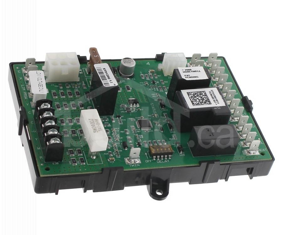
The ST9120U Universal Electronic Fan Timers integrate control of all combustion blower and circulating fan operations in a gas warm air appliance. This control is the central wiring point for most of the electrical components in the furnace. The basic purposes of the ST9120U are to monitor the thermostat for heat, cool and fan demands, run the induced draft blower motor and run a circulating fan (up to two speeds) as required.The electronic fan timers also monitor limit switch strings and energize separate ignition control systems through spst pressure switches. The ST9120U can replace any ST9101 or ST9120 listed in Table 2 below.The electronic fan timers feature a field-adjustable heat fan-on delay, a field-adjustable heat fan-off delay, a field-adjustable cool fan-on delay and a fixed cool fan off delay.
Electronic air cleaner (EAC) and humidifier (HUM) convenience terminal connections are provided as an option. Continuous low speed indoor air circulation is also provided.
SPECIFICATIONS


INSTALLATION
When Installing this Product…
- Read these instructions carefully. Failure to follow them could damage the product or cause a hazardous condition.
- Check the ratings and specifications given in the instructions and on the product to make sure the product is suitable for your application.
- Installer must be a trained, experienced service technician.
- After installation is complete, check out the product operation as provided in these instructions.
WARNING: Electrical Shock Hazard.Can cause severe injury, death or property damage.Disconnect power supply before wiring to prevent electrical shock or equipment damage.More than one disconnection can be required.
Location and MountingMount the ST9120U Electronic Fan Timer in the appliance wiring compartment using the four provided No. 6 self-tapping screws.
WiringMake sure that all wiring complies with local codes and ordinances. Disconnect power before making wiring connections. Refer to Figs. 1, 2, 3 and 4 for standard wiring connections. Refer to Figs. 5 and 6 for internal schematics. Refer to Fig. 7 for schematic of provided ST9101 wiring adapter.
Setting Adjustable Heat Fan DIP SwitchesSet the heat fan-on delay and cool fan-on delay DIP switches as shown in Fig. 8. The heat-on delay time starts when the main gas valve is energized at the start of a thermostat call for heat; the heat-off delay time starts when the main gas valve is de-energized at the end of a thermostat call for heat. The cool fan-on delay time starts when the compressor is energized at the start of a thermostat call for cool.
ST9120 to ST9120U Wiring Conversion Instructions
- Turn off power to appliance. Carefully remove each wire and connect directly to the corresponding location on the new ST9120U control board. Be careful to directly connect to the new terminal with the same labeled identity or label each wire prior to removing from the original board. If original thermostat connection was a quick connect, cut off quick connect, strip wire and insert into terminal block.
- Identify the model number of the board being replaced and set the dip switches based on Table 2.
ST9101 to ST9120U Wiring Conversion Instructions
1. Turn off power to appliance and carefully remove each wire and connect directly to the new ST9120U control board before removing the existing control.Use Table 1 to determine the proper ST9120U terminal for each corresponding ST9101 connection board. Be careful to directly connect to the new terminal or label each wire prior to removal from original board.
Table 1. ST9101 to ST9120U Wiring Conversions
| Terminal | Terminal |
| ST9101 | ST9120U |
| heat | heat |
| cool | cool |
| S | S |
| M1 | Unused Motor Leads |
| M2 | Unused Motor Leads |
| N | Neutral 1 |
| N | Neutral 2 |
| ACC | * for systems with one on fan speed (see note below) |
| X | X sec |
| C | C xfmr |
| thermostat terminals | |
| R | R |
| Y | Y |
| C | C |
| W | W |
| G | G |
ACC terminal is used in ST9101 systems, which use the same fan speed for both heating and cooling. In order to use the ST9120 to replace ST9101 devices in this type of system, the fan connection that originally was connected to ACC on the ST9101 needs to be connected to both heat and cool connections on the ST9120U.2. Unplug the 9-pin connector and plug existing wiring harness directly into the 9-pin connector found on the ST9101 wiring adapter.3. Plug the 6-pin connector found on the ST9101 wiring adapter directly to the open 6-pin connector on the new ST9120U control board.4. Take the two remaining white wires on the ST9101 wiring adapter and connect to Neutral quick connect terminals 3 and 4 on the ST9120U5. Take the black wire on the ST9101 wiring adapter and connect to the S1 quick connect terminal on the ST9120U6. Take the blue wire on the ST9101 wiring adapter and connect to the D1 quick connect terminal on the ST9120U7. Identify the model number of the board being replaced and set the dip switches based on Table 2.
Table 2. Recommended Default Dip Switch Settings
| Model Number | Original OEM Appliance | 1 | 2 | 3 | 4 |
| ST9101A1006 | Rheem | off | on | off | on |
| ST9101A1014 | Rheem | off | on | off | on |
| ST9101A1022 | Trade | off | on | off | on |
| ST9120A1006 | Armstrong | off | on | off | on |
| ST9120A2004 | Armstrong | off | off | on | off |
| ST9120B1005 | Ducane | off | off | off | on |
| ST9120C1012 | Snyder General | off | on | off | off |
| ST9120C1020 | Nordyne | off | on | off | off |
| ST9120C2002 | York | off | on | off | on |
| ST9120C2010 | Ducane | off | on | off | on |
| ST9120C2028 | Armstrong | off | on | off | on |
| ST9120C3000 | ICP | on | off | on | on |
| ST9120C3018 | Bard | off | on | off | off |
| ST9120C4008 | ICP | on | off | on | on |
| ST9120C4016 | ICP | on | off | on | on |
| ST9120C4040 | ICP | on | off | on | on |
| ST9120C4057 | ICP | on | off | on | on |
| *ST9120C5005 | ICP | off | off | on | on |
| *ST9120C5013 | ICP | off | off | on | on |
| *ST9120D3009 | Goodman | off | off | on | on |
| ST9120G2008 | ICP | on | on | off | off |
| ST9120G2016 | ICP | on | on | off | on |
| ST9120G2024 | Skymark | on | off | off | on |
| ST9120G2032 | Skymark | off | off | off | on |
| ST9120G4004 | ICP | on | off | on | on |
| ST9120G4012 | ICP | on | off | on | on |
| ST9120G4038 | Trade | on | off | on | on |
| ST9120U1003 | Trade | off | off | on | on |
| *ST9120U Factory Default Setting |
Heat fan off delay setting may need adjustment based on performance. See Figure 8 to adjust timings.

Fig. 1. Typical ST9120U wiring connections with S8600 Intermittent Pilot Ignition Module.
- CONNECT ONLY IF CONTINUOUS SPEED IS AVAILABLE AND USED.
- CONNECT ONLY IF CONTINUOUS SPEED IS NOT USED.
- CONNECT IF EAC AND HUM TERMINALS ARE AVAILABLE AND USED.
- SOME MODELS USE MALE 1/4-INCH QUICK-CONNECTS INSTEAD OF SCREW TERMINALS FOR THERMOSTAT CONNECTIONS.
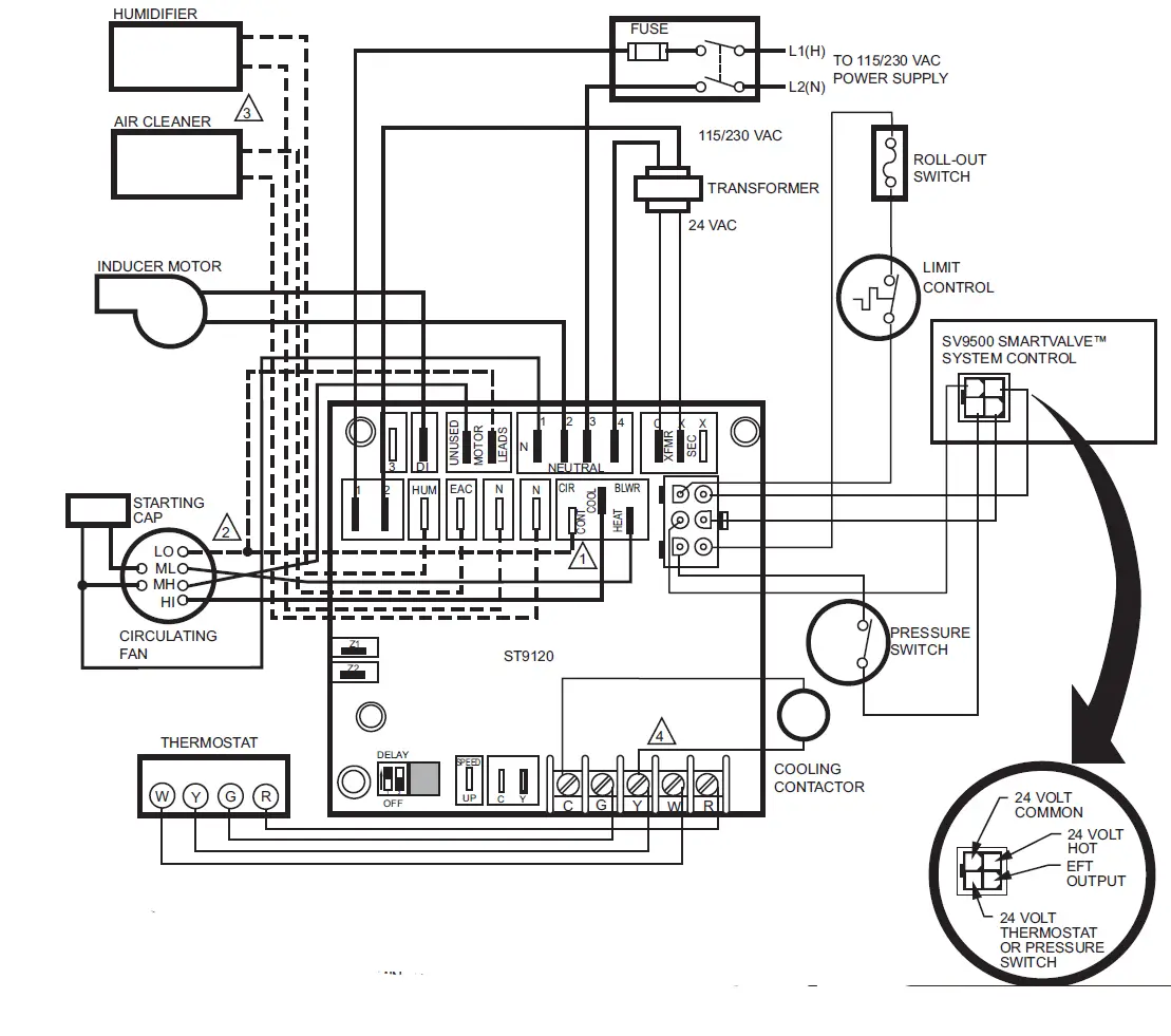
Fig. 2. Typical ST9120U wiring connections with SV9500/SV9501 SmartValve™ System Control.
- CONNECT ONLY IF CONTINUOUS SPEED IS AVAILABLE AND USED.
- CONNECT ONLY IF CONTINUOUS SPEED IS NOT USED.
- CONNECT IF EAC AND HUM TERMINALS ARE AVAILABLE AND USED.
- SOME MODELS USE MALE 1/4-INCH QUICK-CONNECTS INSTEAD OF SCREW TERMINALS FOR THERMOSTAT CONNECTIONS.

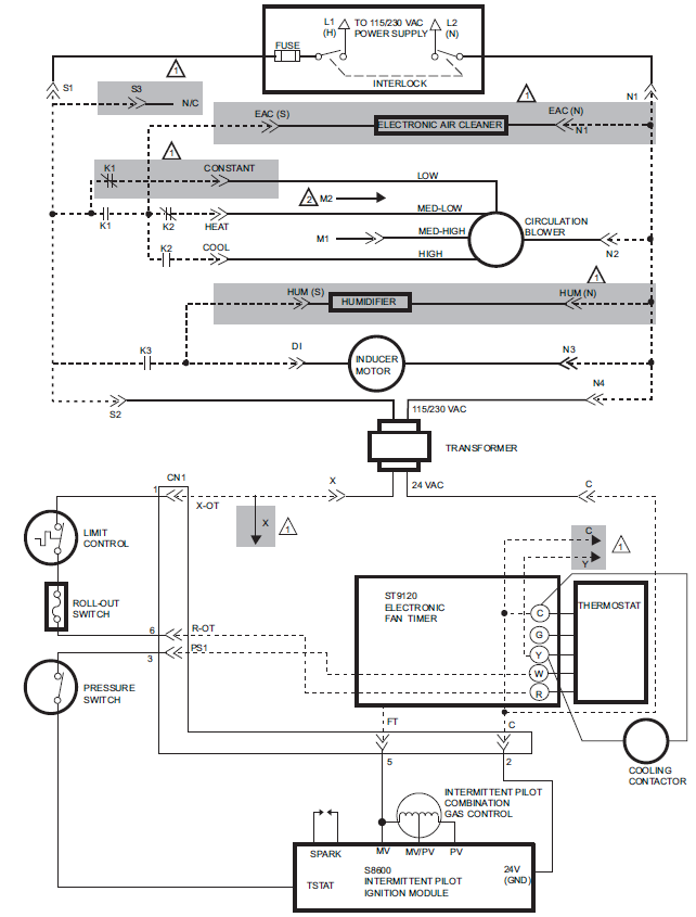
Fig. 5. ST9120U internal schematic for Intermittent Pilot application.
- DENOTES OPTIONAL CONNECTIONS, COMPONENTS AND ACCESSORIES.
- CIRCULATION BLOWER LOW SPEED TAP CONNECTED TO OPTIONAL CONTINUOUS FAN SPEED TERMINAL IS SHOWN.CONNECT CIRCULATION BLOWER LOW SPEED TAP TO M2 IF CONTINUOUS FAN OPTION NOT PROVIDED.
NOTE: DOTTED LINES REPRESENT PRINTED CIRCUIT BOARD WIRING.
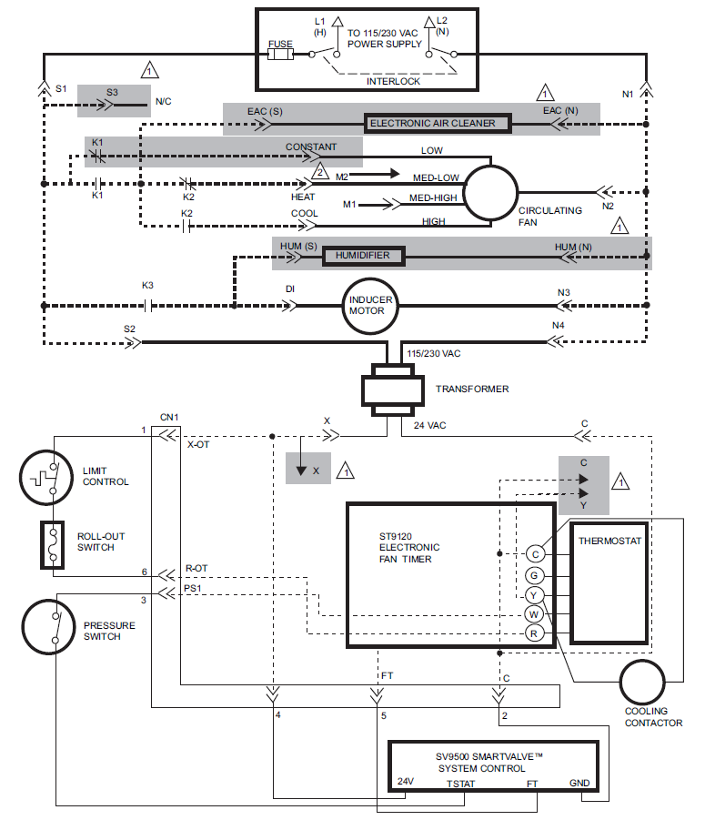
Fig. 6. ST9120U internal schematic for SmartValve™ System applications.
- DENOTES OPTIONAL CONNECTIONS, COMPONENTS AND ACCESSORIES.
- CIRCULATION BLOWER LOW SPEED TAP CONNECTED TO OPTIONAL CONTINUOUS FAN SPEED TERMINAL IS SHOWN.CONNECT CIRCULATION LOW SPEED TAP TO M2 IF CONTINUOUS FAN SPEED OPTION IS NOT PROVIDED.
NOTE: DOTTED LINES REPRESENT PRINTED CIRCUIT BOARD WIRING.
Table 3. ST9101 Wire Adapter Connections
| Color | Function | 6pin Connector Pin Number | 9pin Connector Pin Number |
| White | L2 Neutral | QC | 1 |
| White | L2 Neutral | QC | 2 |
| Orange | pressure switch to main valve | 3 | 3 |
| Red | limit | 6 | 4 |
| Red | limit | 1 | 5 |
| – | open | 4 | – |
| Black | L1 Hot | QC | 6 |
| Yellow | 24V ground | 2 | 7 |
| Violet | main valve sense | 5 | 8 |
| Blue | inducer | QC | 9 |


CHECKOUTOperate the system through at least one complete heating cycle and cooling cycle to make sure the system operates properly. Troubleshoot by checking for appropriate voltages at the ST9120U terminals controlling the combustion blower and heat and cool speed circulating fan. The ST9120U schematics show internal switching to clarify operation and assist in troubleshooting. See Figs. 5 and 6.
Table 4. ST9120U Operating Sequence.
| Action | System Response |
| Thermostat calls for heat. (Terminal W is energized.) | 1. Combustion air blower is energized.
2. Air proving switch makes (air flow is established) 3. Ignition system is energized. 4. Gas valve opens and main burner lights. 5. Heat fan-on delay timing begins. When timing is complete, circulating fan is energized at heat speed. |
| Thermostat ends call for heat. (Terminal W is de-energized.) | 1. Ignition system is de-energized and gas valve closes.
2. Combustion air blower is de-energized after postpurge timing. 3. Heat fan-off delay timing begins. When timing is complete, the circulating fan is de-energized. |
| Thermostat begins call for cool. (Terminals G and Y are energized.) | 1. Cooling contactor is energized.
2. Circulating fan is energized at cool speed after cool fan-on delay timing. |
| Thermostat ends call for cool. (Terminals G and Y are de-energized.) | 1. Cooling contactor is de-energized.
2. Circulating fan is de-energized after cool fan-off delay timing. |
| Thermostat begins call for fan. (Terminal G is energized.) | 1. Circulating fan is energized at heat speed two seconds after G terminal is energized.
2. If a call for heat occurs, circulating fan continues to run at heat speed.] 3. If a call for cool occurs, circulating fan switches to cool speed after four-second delay. NOTE: Circulating fan can be switched off for several seconds during the transition between fan speeds. |
| Thermostat ends call for fan. (Terminal G is de-energized.) | Circulating fan is de-energized. |
| Action | System Response |
| Limit switch string opens. | 1. Thermostat and ignition system are de-energized and gas valve closes.
2. Combustion air blower and circulating fan heat speed are ener- gized. |
| Limit switch string remakes. | 1. Combustion air blower remains energized for postpurge timing.
2. The circulating fan remains energized for the selected delay-off timing. 3. Normal operation resumes. |
| Continuous circulating fan is connected. (Optional connection to circulating fan low speed tap.) | 1. Circulating fan low speed is energized when there is no call for heat, cool, or fan.
2. If fan operation is required by a call for heat, cool, or fan, ST9120U switches circulating fan to appropriate speed. |
| Electronic air cleaner is connected. (Optional connection to 120 Vac electronic air cleaner.) | 1. In two-speed systems, the electronic air cleaner is energized when the heat or cool speed of the circulating fan is energized.
2. If continuous fan option is used, connect EAC to line voltage input S1. Line voltage hot lead is also connected in input S1. |
| Humidity control is connected. (Optional connection to 120 Vac humidifier.) | Humidifier is energized when combustion air blower is energized. |
Resideo Technologies, Inc.1985 Douglas Drive North, Golden Valley, MN 554221-800-468-150269-0644—02 M.S. Rev. 10-20 | Printed in United States
© 2020 Resideo Technologies, Inc. All rights reserved.This product is manufactured by Resideo Technologies, Inc. and its affiliates.
 report this ad
![]()
[xyz-ips snippet=”download-snippet”]