
![]()
TB7220U CommercialPRO™ Programmable Thermostat
INSTALLATION INSTRUCTIONS
APPLICATIONThe TB7220U Programmable Thermostat provides electronic control of 24 Vac heating and cooling systems. See Table 1 for a description.
Table 1. TB7220U Thermostat Description.
|
Feature |
Description |
| Powering Methods | • Battery only
• Direct connection to a 24 Vac transformer only • Direct connection to a 24 Vac transformer with battery backup |
| System Types | • Conventional (up to 2 Heat, 2 Cool stages)
• Heat Pump (up to 3 Heat, 2 Cool stages) |
| Changeover | Manual or automatic changeover (selectable) |
| System Setting | Heat-Off-Cool-Auto |
| Fan Setting | Auto-On |
 MERCURY NOTICEIf this control is replacing a control that contains mercury in a sealed tube, do not place your old control in the trash. Dispose of properly. Contact your local waste management authority for instructions regarding recycling and the proper disposal of an old control.
INSTALLATIONWhen Installing this Product…
- Read these instructions carefully. Failure to followthem could damage the product or cause a hazardous condition.
- Check ratings given in instructions and on the product to ensure the product is suitable for your application.
- Installer must be a trained, experienced service technician.
- After installation is complete, check out product operation as provided in these instructions.
CAUTIONElectrical Shock or Equipment Damage Hazard.Can shock individuals or short equipment circuitry.Disconnect power supply before installation.
Select Thermostat LocationSelect a location for the thermostat about 5 ft (1.5m) above the floor in an area with good air circulation at average temperature. See Fig. 1.
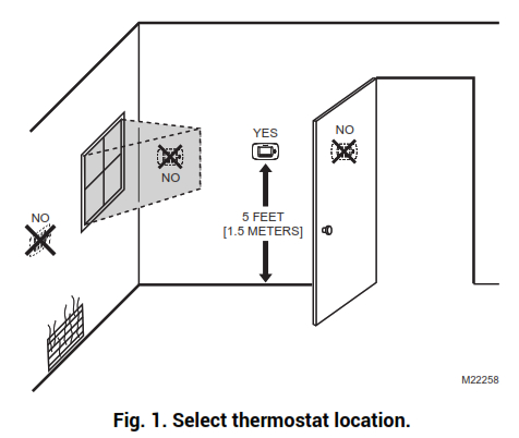 Fig. 1. Select thermostat location.Do not install the thermostat where it can be affected by:— Drafts or dead spots behind doors and in corners.— Hot or cold air from ducts.— Radiant heat from sun or appliances.— Concealed pipes and chimneys.— Unheated (uncooled) areas such as an outside wall behind the thermostat.

TB7220U COMMERCIALPRO™ PROGRAMMABLE THERMOSTAT
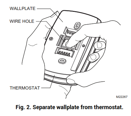
Separate Wallplate from Thermostat1. Separate the wallplate from the thermostat. See Fig. 2.
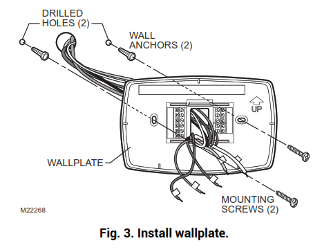
Install Wallplate (See Fig. 3)
Mount the thermostat horizontally on the wall:
- Pull the wires through the wire hole on the wallplate.
- Position the wallplate on the wall with the arrow pointing up. Level the wallplate for appearance only.
- Use a pencil to mark the mounting holes.
- Remove the wallplate from the wall and drill two 3/16 in. holes in the wall (if drywall) as marked. For firmer material such as plaster, drill two 7/32 in. holes. Tap the wall anchors (provided) into the drilled holes until flush with the wall.
- Pull the wires through the wire hole on the wallplate and position the wall plate over the wall anchors.
- Insert the mounting screws into the wall anchors and tighten them.
WIRINGIMPORTANT— All wiring must agree with applicable codes, ordinances, and regulations.— Use 18 gauge thermostat wire. A shielded cable is not required.NOTES:— Sensor wires must have a cable separate from the thermostat control cable.— Refer to Table 2 for terminal designation descriptions.— See Fig. 6 through 16 for wiring diagrams for specific equipment applications.
- Select a set of terminal identifications that correspond to your system type (conventional or heat pump). (See Fig. 4).

- Loosen screw terminals used for the application.
- Insert the wires into the terminal block and tighten each screw terminal.
- Push excess wire back into the wall opening and restrict wires to the shaded area. See Fig. 5.
- Plug the wall opening with nonflammable insulation to prevent drafts from affecting the thermostat.

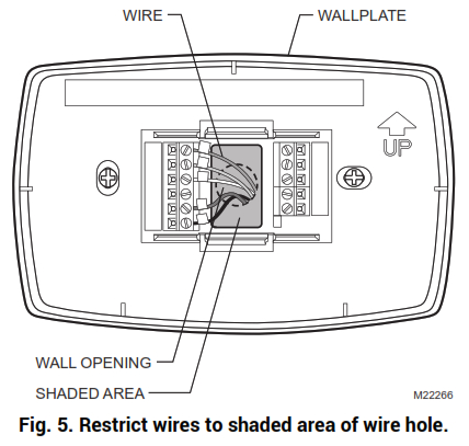
Table 2. Terminal Designation Descriptions.
| Terminal Designation | Description |
| RC (see Note 1) | Power for cooling—connect to secondary side of cooling system transformer. |
| R (see Note 1) | Power for heating—connect to secondary side of heating system transformer. |
| Y | Compressor output. |
| C (see Note 2) | Common wire from the secondary side of cooling system transformer. |
| W | Heat relay. |
| G | Fan relay. |
| W2 | Second stage heat relay. |
| Y2 | Second stage cooling. |
| O/B (see Note 3) | Changeover valve for heat pumps. |
| A (see Note 4) | Economizer/Time-Of-Day (TOD) output—powered via RC terminal. |
| S1 (See Note 5) | Optional outdoor or indoor remote sensor. |
| S2 (See Note 5) | Optional outdoor or indoor remote sensor. |
| W1 | Auxiliary Heat Relay Output (Head Pump Mode 2H/1C, 3H/2C) |
NOTES:
- When used in a single-transformer system, leave metal jumper wire in place between RC and R. If used on a two-transformer system, remove metal jumper wire between RC and R.
- Common wire is optional when thermostat is used with batteries. When using separate transformers for heating and cooling, the common must come from the cooling transformer.
- If thermostat is configured for a heat pump in the Installer Setup, configure the changeover valve for cool (O-factory setting) or heat (B).
- Reference economizer literature for wiring details. When set for economizer operation, the A terminal provides the occupancy signal. (Power indicates occupied.)
- Sensor wires must have a cable separate from the thermostat control cable.
Terminal “A” Wiring Details for Economizers
— Wire the A terminal to the W7212 “N” terminal, or the W7459 “TR” terminal.— When using dual transformers at the thermostat, the cooling transformer must power the economizer.— The A signal is powered from the RC terminal and energizes the economizer to signal occupied status and drive the damper to the set minimum position.
Table 3. Wiring Diagrams.
|
System Type |
Wallplate Terminal Identifications |
Wiring Diagram Figure |
| Standard Heat/Cool | Conventional | 6, 7 |
| Heat Only | Conventional | 8 |
| Heat Only with Fan | Conventional | 9 |
| Cool only | Conventional | 10 |
| Standard Multistage up to 2 Heat/2 Cool | Conventional | 11, 12 |
| Heat Pump(No Auxiliary Heat) | Heat Pump | 13, 14 |
| Heat Pump(with Auxiliary Heat) | Heat Pump | 15, 16 |
| Multiple TR21 Sensors | — | 17, 18, 19 |
| Multiple C7189U Sensors | — | 20 |
Conventional System Wiring
- POWER SUPPLY. PROVIDE DISCONNECT MEANS AND OVERLOAD PROTECTION AS REQUIRED.
- FACTORY-INSTALLED JUMPER.
- WHEN USING BATTERIES, THE 24V COMMON CONNECTION IS OPTIONAL.M23011Fig. 6. Typical wiring of single transformer 1H/1C system.

- POWER SUPPLY. PROVIDE DISCONNECT MEANS AND OVERLOAD PROTECTION AS REQUIRED.
- REMOVE FACTORY-INSTALLED JUMPER.
- WHEN USING BATTERIES, THE 24V COMMON CONNECTION IS OPTIONAL. WHEN USED, THE COMMON MUST CONNECTTO THE COOLING TRANSFORMER SECONDARY.M23012Fig. 7. Typical hookup of dual transformer 1H/1C system.
- POWER SUPPLY. PROVIDE DISCONNECT MEANS AND OVERLOAD PROTECTION AS REQUIRED.
- FACTORY-INSTALLED JUMPER.
- WHEN USING BATTERIES, THE 24V COMMON CONNECTION IS OPTIONAL.M23013
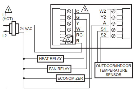
Fig. 8. Typical hookup of heat-only system.
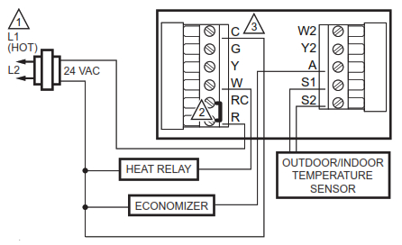
- POWER SUPPLY. PROVIDE DISCONNECT MEANS AND OVERLOAD PROTECTION AS REQUIRED.
- FACTORY-INSTALLED JUMPER.
- WHEN USING BATTERIES, THE 24V COMMON CONNECTION IS OPTIONAL.M23014Fig. 9. Typical hookup of heat-only system with fan.
- POWER SUPPLY. PROVIDE DISCONNECT MEANS AND OVERLOAD PROTECTION AS REQUIRED.
- FACTORY-INSTALLED JUMPER.
- WHEN USING BATTERIES, THE 24V COMMON CONNECTION IS OPTIONAL.M23015Fig. 10. Typical hookup of cool-only system.

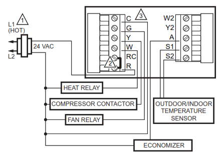
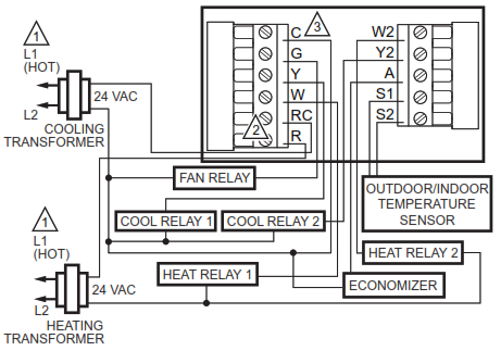
- POWER SUPPLY. PROVIDE DISCONNECT MEANS AND OVERLOAD PROTECTION AS REQUIRED.
- FACTORY-INSTALLED JUMPER.M23016
- WHEN USING BATTERIES, THE 24V COMMON CONNECTION IS OPTIONAL.Fig. 11. Typical hookup of single transformer multistage system (up to 2H/2C).

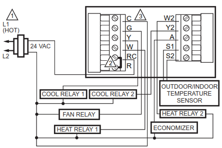
- POWER SUPPLY. PROVIDE DISCONNECT MEANS AND OVERLOAD PROTECTION AS REQUIRED.
- REMOVE FACTORY-INSTALLED JUMPER.
- WHEN USING BATTERIES, THE 24V COMMON CONNECTION IS OPTIONAL. WHEN USED, THE COMMON MUST CONNECT TO THE COOLING TRANSFORMER SECONDARY.M23017Fig. 12. Typical hookup of dual transformer multistage system (up to 2H/2C).
Heat Pump System Wiring

- POWER SUPPLY. PROVIDE DISCONNECT MEANS AND OVERLOAD PROTECTION AS REQUIRED.
- FACTORY-INSTALLED JUMPER.
- WHEN USING BATTERIES, THE 24V COMMON CONNECTION IS OPTIONAL.
- “O/B” TERMINAL IS SET TO CONTROL AS EITHER “O” OR “B” IN THE INSTALLER SETUP.
- OPTIONAL OUTDOOR OR INDOOR REMOTE SENSOR. WIRES MUST HAVE A CABLE SEPARATE FROM THE THERMOSTAT CABLE.M23018Fig. 13. Typical hookup of a single-stage heat pump with no auxiliary heat (1H/1C).
- POWER SUPPLY. PROVIDE DISCONNECT MEANS AND OVERLOAD PROTECTION AS REQUIRED.
- FACTORY-INSTALLED JUMPER.
- WHEN USING BATTERIES, THE 24V COMMON CONNECTION IS OPTIONAL.
- “O/B” TERMINAL IS SET TO CONTROL AS EITHER “O” OR “B” IN THE INSTALLER SETUP.
- OPTIONAL OUTDOOR OR INDOOR REMOTE SENSOR. WIRES MUST HAVE A CABLE SEPARATE FROM THE THERMOSTAT CABLE.M23019Fig. 14. Typical hookup of a multistage heat pump with no auxiliary heat (2H/2C).
- POWER SUPPLY. PROVIDE DISCONNECT MEANS AND OVERLOAD PROTECTION AS REQUIRED.
- FACTORY-INSTALLED JUMPER.
- WHEN USING BATTERIES, THE 24V COMMON CONNECTION IS OPTIONAL.
- “O/B” TERMINAL IS SET TO CONTROL AS EITHER “O” OR “B” IN THE INSTALLER SETUP.
- OPTIONAL OUTDOOR OR INDOOR REMOTE SENSOR. WIRES MUST HAVE A CABLE SEPARATE FROM THE THERMOSTAT CABLE.M23020Fig. 15. Typical hookup of a single-stage heat pump with auxiliary heat (2H/1C).
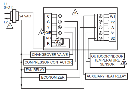
- POWER SUPPLY. PROVIDE DISCONNECT MEANS AND OVERLOAD PROTECTION AS REQUIRED.
- FACTORY-INSTALLED JUMPER.
- WHEN USING BATTERIES, THE 24V COMMON CONNECTION IS OPTIONAL.
- “O/B” TERMINAL SET TO CONTROL AS EITHER “O” OR “B” IN THE INSTALLER SETUP.
- OPTIONAL OUTDOOR OR INDOOR REMOTE SENSOR. WIRES MUST HAVE A CABLE SEPARATE FROM THE THERMOSTAT CABLE.M23021
Fig. 16. Typical hookup of a multistage heat pump with auxiliary heat (3H/2C).
Sensor Wiring for Temperature Averaging
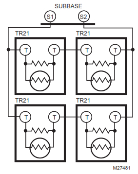 Fig. 17. Wiring four T7770A1006 (20K ohm) Sensors.
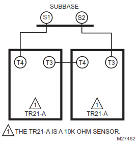
Fig. 18. Wiring two TR21-A (10K ohm) Sensors to provide a temperature averaging network.

Fig. 19. Wiring two TR21 (20K ohm) Sensors and one TR21-A (10K ohm) sensor to provide a temperature averaging network
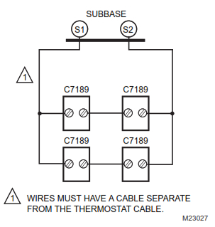 Fig. 20. Wiring four C7189U (10K ohm) Sensors to provide a temperature averaging network.
POWER THE THERMOSTAT
You can choose from three methods to power the thermostat:
- Batteries only (AA alkaline).
- 24 Vac direct connection only.
- 24 Vac direct connection with battery backup (AA alkaline).
Wiring 24 Vac Common
- Single-Transformer System—Connect the common side of the transformer to the C screw terminal of the thermostat wall plate. Leave the metal jumper wire in place between RC and R.
- Two-Transformer System—Connect the common side of the cooling transformer to the C screw terminal of the thermostat wall plate. Remove the metal jumper wire between RC and R.
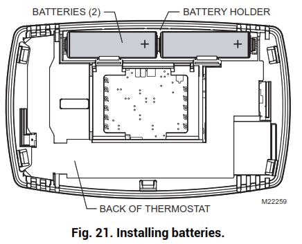
Installing Batteries
- Install two AA alkaline batteries on the back of the thermostat as marked. See Fig. 21.
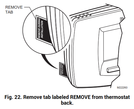
- Locate and remove the tab labeled Remove. SeeFig. 22.IMPORTANTThis tab must be removed in order to set the real-time clock.
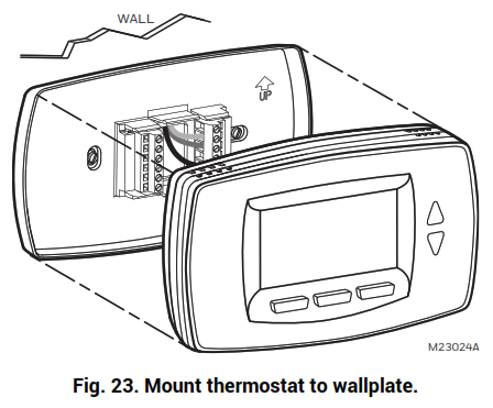
Mount Thermostat to Wallplate
- Align the terminal screw blocks with the pins on the back of the thermostat.
- Push the thermostat straight onto the wallplate until it snaps into place. See Fig. 23.
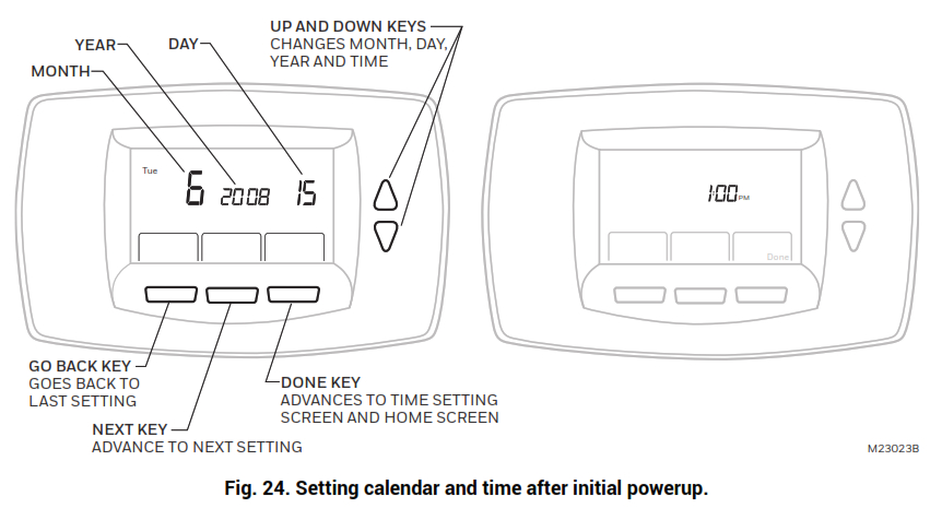
SETTING CALENDAR AND TIME
This thermostat is designed to, under normal use, automatically keep current time and day in memory for up to ten years once the calendar is set. There are two ways to set the calendar and time for this thermostat:
SETTING DATE/TIME WHEN THERMOSTAT IS FIRST POWEREDWhen the thermostat is first powered, the display is readyto set the calendar and time. The thermostat proceeds through a sequence of setup screens. See Fig. 24.
SETTING DATE/TIME AFTER THERMOSTAT IS ALREADY FUNCTIONINGUse the installer setup to set year, month and day. See the Installer Setup Numbers, Settings, and Tests section.
ADVANCED SETTINGS
The thermostat has advanced settings to match the HVAC system. These settings can be adjusted to match specific needs. See the following section (Installer Setup Numbers, Settings, and Tests) for details.
INSTALLER SETUP NUMBERS, SETTINGS, AND TESTS (TABLE 4)
Configure Installer Setup
- Press and release the System key.
- Press System and Done keys simultaneously.
- Hold keys for approximately five seconds, until the screen changes.
- When the display changes, release the System and Done keys.
NOTE: See Table 4 for installer setup (ISU) numbers and settings.Installer System TestsUse the Installer System Test section to test the heating, cooling and fan. Refer to the latter portion of Table 4.
 CAUTIONEquipment Damage Hazard. Minimum compressor off time is bypassed during Installer System TestAvoid cycling compressor quickly.
IMPORTANTUse Installer System Test to test heating, cooling, and fan. The setting chosen for System Type (Installer Setup Number 0170) can prevent some System Test Numbers from appearing.
Table 4. Installer Setup Menu.
|
Installer Setup Number |
Installer Setup Name | Default Setting | All Settings |
Notes |
| 0120 | Date (Year Upper) | 20 | 20—20xx
21—21xx |
Available year range: 2001 – 2178 |
| 0130 | Date (Year Lower) | 04 | 00-99 | Available year range: 2001 – 2178 |
| 0140 | Date (Month) | 6 | 1-12 | |
| 0150 | Date (Day) | 15 | 1-31 (Month Dependent) | |
| 0160 | Schedule Options | 4 | 0—Non-Programmable 4—Programmable | |
| 0170 | System Selection | 8 | 1—1H/1C Conv
2—1H/1C HP 3—1H w/o fan 4—1H with fan 6—1C 7—2H/1C HP (Aux. Heat) 8—2H/2C Conv 9—2H/1C Conv 10—1H/2C Conv 11—2H/2C HP 12—3H/2C HP (Aux. Heat) |
To use the Emergency Heat button, select setting #7 or #12. See Fig. 16 or 17 for auxiliary heat wiring. |
| 0175 | TOD/Economizer output (terminal A) | 0 | 0—Unused 1—TOD
2—Economizer |
Economizer energizes A during a call for cool. TOD energizes A during the Occupied period and de-energizes A during the Unoccupied. |
| 0180 | Heat Fan Operation | 0 | 0—System controls fan 1—Thermostat controls fan (ON during call for heat) | Only shown for a conventional system with heat stages (ISU 0170) and fan capability selected. If the heat pump is selected, the fan always operates with Thermostat control.
The only thing that allows the fan to turn off during occupied periods is a manual override of the fan from On to Auto. |
| 0185 | Pre-occupancy Purge Duration | 0 | 0—no duration 1—one hour 2—two hours 3—three hours | Only shown if the thermostat is programmable (ISU 0160). Pre-occupancy purge enabled by nonzero duration (and sends economizer to minimum position). |
| 0190 | Reversing Valve O/B | 0 | 0—O (O/B On Cool)
1—B (O/B On Heat) |
Only shown with heat pump system selected. |
| 0220 | Cycles Per Hour (CPH) for first stage compressor | 3 | 1-6 | Only shown for systems with cool stages (ISU 0170). Selection in this stage changes second stage cool default CPH. |
| 0230 | CPH for second stage compressor | 3 | 1-6 | Only shown for a system with two stages of cool (ISU 0170). |
|
Installer Setup Number |
Installer Setup Name | Default Setting | All Settings |
Notes |
| 0240 | CPH for first stage conventional heat | 5 | 1-12 | Only shown for conventional system with heat stages (ISU 0170).
Selection in this stage changes default CPH of second stage heat. |
| 0250 | CPH for second stage conventional heat | 9 | 1-12 | Only shown for conventional system with at least two stages conventional heat or 2H/1C heat pump (ISU 0170). |
| 0260 | CPH for third Stage Heat | 9 | 1-12 | Only shown for 3H/2C heat pump system (ISU 0170). |
| 0270 | CPH for Auxiliary Heat | 9 | 1-12 | Only shown for multi-stage heat pump system with more heat than cool stages (ISU 0170). |
| 0280 | Continuous Backlight | 0 | 0—No
1—Yes |
Always shown. If AC power not present the option is overridden and normal backlight operation occurs. |
| 0300 | Changeover | 1 | 0—Manual 1—Auto | Only shown for system with both heat and cool stages (ISU 0170). |
| 0310 | Deadband | 3°F (2°C) | 2 (1.5)—2°F (1.5°C)3 (2.0)—3°F (2.0°C)4 (2.5)—4°F (2.5°C)5 (3.0)—5°F (3.0°C)6 (3.5)—6°F (3.5°C)7 (4.0)—7°F (4.0°C)8 (4.5)—8°F (4.5°C)9 (5.0)—9°F (5.0°C) | Only shown for the Auto Changeover system (ISU 0300). |
| 0320 | Temperature Indication Scale | 0 | 0—°F
1—°C |
|
| 0330 | Daylight Saving | 2 | 0—Disabled 1—Enabled (US 1987)2—Enable (US 2007) 3—Enabled (Europe) | |
| 0340 | Remote Temperature Sensor | 0 | 0—None
1—Outdoor for Display 2—Outdoor for Control 3—Remote 10K Indoor 4—Remote 20K Indoor |
Averaging would not include on-board sensor. It is accomplished by series/parallel combinations.
2 applies only to Heat Pump applications (allowing compressor lockout while displaying temperature). |
| 0350 | Heat Pump Compressor Lockout | 0 | 0—None
15(-9.5)—15°F (-9.5°C) 20(-6.5)—20°F (-6.5°C) 25(-4.0)—25°F (-4.0°C) 30(-1.0)—30°F (-1.0°C) 35(1.5)—35°F (1.5°C) 40(4.5)—40°F (4.5°C) 45(7.0)—45°F (7.0°C) |
Only shown for heat pump systems with more heat stages than cool (ISU 0170) and remote outdoor control sensor (ISU 0340 is 2).
Must enforce a dead band between this and Auxiliary Lockout. |
| 0360 | Heat Pump Auxiliary Lockout | 0 | 0—None 40(4.5)—40°F (4.5°C)
45(7.0)—45°F (7.0°C) 50(10.0)—50°F (10.0°C) 55(13.0)—55°F (13.0°C) 60(15.5)—60°F (15.5°C) |
Only shown for heat pump systems with more heat stages than cool (ISU 0170) and remote outdoor control sensor (ISU 0340 at 2).
Must enforce a dead band between this and Heat Pump Compressor Lockout. |
| 0535 | Temporary Occupied Duration Limit | 3 | 0—no duration 1—one hour 2—two hours 3—three hours 4—four hours | 0 means no limit. |
| 0540 | Number of Periods | 4 | 2—2 Periods
4—4 Periods |
Does not appear if Non-programmable is chosen (ISU 0160).
Applies to all days of the week. |
| Installer Setup Number | Installer Setup Name | Default Setting | All Settings | Notes |
| 0580 | Minimum Compressor Off Time | 5 | 0—Off2—2 minutes3—3 minutes4—4 minutes5—5 minutes | Only shown if system has cool stages (ISU 0170). |
| 0600 | Heat Temperature Range Stops | 90 | 40 to 90°F (4 to 32°C) | Only shown if system has heat stages (ISU 0170). |
| 0610 | Cool Temperature Range Stops | 50 | 50 to 99°F (10 to 37°C) | Only shown if system has cool stages (ISU 0170). |
| 0640 | Clock Format | 12 | 12—12 Hour24—24 Hour | |
| 0650 | Extended Fan-on time Heat | 0 | 0—Off90—90 seconds | Not displayed with cool-only systems (ISU 0170) or with fan set to system control (ISU 0180 at 0). |
| 0660 | Extended Fan-on time Cool | 0 | 0—Off40—40 seconds | Only shown for systems with cool stages (see ISU 0170). |
| 0670 | Keypad Lockout | 0 | 0—Unlocked 1—Partial Lockout 12—Partial Lockout 2 3—Fully Locked | Unlocked: All functions accessible.
Partial 1: Locks all but Holiday, Override, and Up/Down. Partial 2: Locks all but Holiday and Override. Full: Entire interface locked/non-functional. |
| 0680 | Temperature Control Heat | 2 | 1—Less Aggressive 2—Standard 3—More Aggressive | Only shown if system has heat stages (ISU 0170).
Only integral gains affected. Affects control operation in all control regimes (not just recovery or setpoint change). More Aggressive stops signal prior to reaching the setpoint. (For use with oversized equipment.) |
| 0685 | Recovery Heat Ramp Rate | 5 | 0-20°F/hour | Only shown if system has heat stages (ISU 0170).
0 disables ramped recovery (step setpoint change at period start time). |
| 0690 | Temperature Control Cool | 2 | 1—Less Aggressive 2—Standard 3—More Aggressive | Only shown if system has cool stages (ISU 0170).
Only integral gains affected. Affects control operation in all control regimes (not just recovery or setpoint change). More Aggressive stops signal prior to reaching the setpoint. (For use with oversized equipment.) |
| 0695 | Recovery Cool Ramp Rate | 3 | 0-20°F/hour | Only shown if system has cool stages (ISU 0170).
0 disables ramped recovery (step setpoint change at period start time). |
| 0700 | Temperature Display Offset | 0 | -3 (-1.5)— -3°F (-1.5°C)
-2 (-1.0)— -2°F (-1.0°C) -1 (-0.5)— -1°F (-0.5°C) 0 (0.0)—0°F (0.0°C) 1 (0.5)—1°F (0.5°C) 2 (1.0)— 2°F (1.0°C) 3 (1.5)—3°F (1.5°C) |
This offset applies to both the control temperature and to the display temperature for the indoor sensor (and remote indoor sensor). |
| 0710 | Restore Factory Defaults | 0 | 0—No
1—Yes |
Resets all ISU parameters to default values and resets the schedule to default (see Table 5). Retains only calendar settings and time. |
| INSTALLER TESTS | ||||
| Test 1 | Installer Test Cool | 0 | 0—Off
1—Cool Stage 1 2—Cool Stage 2 |
|
| Test 2 | Installer Test Fan | 0 | 0—Off 1—Fan On | |
| Test 3 | Installer Test Heat | 0 | 0—Off
1—Heat Stage 1 2—Heat Stage 1 and 2 3—Heat Stage 1,2 and 3 |
|
| Test 4 | Installer Test Auxiliary Heat | 0 | 0—Auxiliary Heat Off 1—Auxiliary Heat On | |
| Test 8 | Installer Test TOD/Economizer | 0 | 0—TOD/Economizer Off 1—TOD/Economizer On |
NOTE: Press the Done key to exit the Installer System Test.
OPERATION
System SettingsHeat—The thermostat controls the heating system.Off—Both heating and cooling systems are off.Cool—Thermostat controls the cooling system.Auto—Thermostat automatically changes between heatand cool operation, depending on indoor temperature.Fan SettingsAuto —Fan runs only when heating/cooling system is on.On—Fan runs continuously.Table 5 shows default program settings. See Owner’sGuide for complete instructions to change the program.
Table 5. Default Program Settings.
| Schedule Period | Time |
Setpoints |
Fan Setting | |
| Heat | Cool | |||
| Occ1 | 8:00am | 70°F (21°C) | 75°F (25.5°C) | On |
| Unocc1 | 10:00pm | 55°F (10°C) | 85°F (24°C) | Auto |
| Occ2 | 1:00pm | 70°F (21°C) | 75°F (25.5°C) | On |
| Unocc2 | 12:00pm
(Noon) |
55°F (10°C) | 85°F (24°C) | Auto |
Minimum-Off Timer (Compressor Protection)
The thermostat has an adjustable Minimum-Off Timer that can be set from zero to five minutes (Factory Setting—five minutes). The Minimum-Off Timer can be bypassed through the Installer System Test or it can be bypassed permanently by setting the Minimum-Off Timer to 0 minutes in the Installer Setup. The MinimumOff Timer is activated after the compressor turns off:— If the thermostat is a system powered (common wire), the Minimum-Off Timer is also activated upon initial startup and after power interruptions.— If there is a call for cooling or heating during the Minimum-Off Time, the thermostat displays “Wait.”— When the Minimum Off Timer expires, “Cool On” or “Heat On” (heat pumps only)” appears solidly in the display, and the compressor and fan turn on.
Outdoor or Indoor Temperature Sensor
Allow outdoor or indoor temperature sensors to absorb the air for a minimum of five minutes before taking a reading. See the Sensor instructions for more information.
Economizer/TOD Logic (Table 6)
Table 6. Operation of Terminal A.
|
Effective Occupancy |
Call for Cool |
Terminal A |
|
| Economizer |
TOD |
||
| Occupied | — | Energized | Energized |
| Unoccupied | Yes | Energized | De-energized |
| No | De-energized | De-energized | |
| Override | — | Energized | Energized |
Heat Pump Temperature Lockouts
Dual Fuel Heat Pump and Outdoor SensorIn this operation, there is no external fossil fuel kit (dual fuel kit) installed; the thermostat controls this function:
- Choose correct heat pump application in Installer Setup Number 0170.
- Choose Outdoor Temperature Sensor for Heat Pump Temperature Lockouts Option in Installer Setup Number 0340.
- Choose appropriate Balance Point Temperature in Installer Setup Number 0350.
OPERATION IN HEAT MODE ABOVE BALANCE POINT (OUTDOOR TEMPERATURE)When the outdoor temperature is above the selected Balance Point Temperature (ISU 0350), only the compressor operates and the fan (G terminal) energizeswhen the thermostat calls for heat.
OPERATION IN HEAT MODE BELOW BALANCE POINT (OUTDOOR TEMPERATURE)When the outdoor temperature is below the selected Balance Point Temperature (ISU 0350), only the Fossil Fuel (auxiliary heat) operates and the fan (G terminal) does not energize when the thermostat calls for heat.
Heat Pump with Auxiliary (Backup) Heat and Outdoor Temperature Sensor
- Choose the correct heat pump application in Installer Setup Number 0170.
- Choose Outdoor Temperature Sensor for Control Option in Installer Setup Number 0340.
- Choose Compressor Lockout Temperature in Installer Setup Number 0350.
- Choose Auxiliary Lockout Temperature in Installer Setup Number 0360.
NOTE: There is a 5°F Deadband between Compressor and Auxiliary Heat lockout temperatures.
Operation in Heat ModeWhen the outdoor temperature is:— Below the Compressor Lockout Temperature, only the Auxiliary Heat operates.— Above the Auxiliary Lockout Temperature, only the Compressor operates. See Fig. 31.— Between the two temperatures, both the Compressor and Auxiliary Heat operate.

TROUBLESHOOTING (TABLE 7)
Table 7. Troubleshooting.
|
Symptom |
Possible Cause |
Action |
| The display does not come on. | Thermostat is not being powered. | Check for 24 Vac between C and RC. Check that AA batteries are installed correctly and are good. |
| Temperature settings do not change. | The upper or lower temperature limits were reached. | Check temperature setpoints.Check Installer Setup Numbers 0600 and 0610; modify as needed. |
| The keypad is fully locked. | Check Installer Setup Number 0670 to change keypad locked options. | |
| Heating or cooling does not come on. | Thermostat minimum off-time is activated. | Wait up to five minutes for the system to respond. |
| System selection not set to Heat or Cool. | Set system Selection to correct position. | |
| System type Selection is incorrect. | Check Installer Setup Number 0170 and make sure correct System type is chosen. | |
| Thermostat is calling for Heat (Heat on) or Cool (Cool on) but no heating or cooling is running. | Heating or cooling equipment is not operating. | Check wiring. Check Installer Setup Number 0170 and make sure correct system type is chosen. Verify operation of equipment in System Test mode. |
| Heat does not turn on (Heat On is solid in the display). | Heating equipment failure. | Check for 24 Vac at the equipment on the secondary side of the transformer between power and common. If voltage is not present, check the heating equipment to find the cause of the problem.
Check for 24 Vac between the heat terminal (W) and transformer common. If 24 Vac is present, the thermostat is functional. Check the heating equipment to find the cause of the problem. |
| Loose or broken wire connection between thermostat and heating equipment. | Check for 24 Vac between the heat terminal
(W) and transformer common. If voltage is not present, check wire connection (loose or broken) between the thermostat and the heating equipment. |
|
| Heat pump puts out cool air in the heat mode and warm air in the cool mode. | Changeover Valve (Installer Setup Number 0190) is not configured to match the changeover required by the installed heat pump. | Set Changeover Valve (Installer Setup Number 0190) to match the changeover required by the installed heat pump. |
| Both the heating and cooling equipment are running at the same time. | The heating equipment is not a heat pump but the System Type (Installer Setup Number 0170) is set to Heat Pump. | Set System Type (Installer Setup Number 0170) to match the installed heating and/or cooling equipment. |
| Heating and cooling wires are shorted together. | Separate the shorted heating and cooling wires. | |
| Cooling does not turn on (Cool On is solid in the display). | Cooling equipment failure. | Check for 24 Vac at the equipment on the secondary side of the transformer between power and common. If voltage is not present, check the cooling equipment to find the cause of the problem. Check for 24 Vac between the cool terminal
(Y) and transformer common. If 24 Vac is present, the thermostat is functional. Check the cooling equipment to find the cause of the problem. |
| Loose or broken wire connection between thermostat and cooling equipment. | Check for 24 Vac between the cool terminal
(Y) and transformer common. If voltage is not present, check the wire connection (loose or broken) between the thermostat and the cooling equipment. |
|
| Fan does not turn on in a call for heat (electric furnace). | Fan Control in Heating is set to Gas or Oil Furnace (Setting 0180). | Set Fan Control in Heating to Electric Furnace (Setting 0180). |
| Heating equipment is running in the cool mode. | Heating equipment is not a heat pump but System Type (Installer Setup Number 0170) is set to Heat Pump. | Set System Type (Installer Setup Number 0170) to match the installed heating and/or cooling equipment. |
| Heating equipment does not turn off and heat temperature setting is set below room temperature (Heat On is not in the display). | Heating equipment is not a heat pump but System Type (Installer Setup Number 0170) is set to Heat Pump. | Set System Type (Installer Setup Number 0170) to match the installed heating and/or cooling equipment. |
| Cannot set the system setting to Heat. | System Type (Installer Setup Number 0170) is set to Cool Only. | Set System Type (Installer Setup Number 0170) to match the installed heating and/or cooling equipment. |
| Cannot set the system setting to Cool. | System Type (Installer Setup Number 0170) is set to Heat Only or Heat Only with Fan. | Set System Type (Installer Setup Number 0170) to match the installed heating and/or cooling equipment. |
| Heat On is not in the display. | System setting is not set to Heat and/or temperature setting is not set above room temperature. | Set the system setting to Heat and set the temperature setting above the room temperature. |
| Cool On is not in the display. | System setting is not set to Cool and/or the temperature setting is not set below room temperature. | Set the system setting to Cool and set the temperature setting below the room temperature. |
| Wait is in the display. | Compressor minimum off timer is active. | Wait up to five minutes for the cooling or heating (heat pump) equipment to turn on. |
SPECIFICATIONS
Electrical Ratings:
|
Terminal |
Voltage (50/60 Hz) | Running Current |
| W (Heating) | 20 – 30 Vac | 0.02 – 1.0A |
| Y (Cooling) | 20 – 30 Vac | 0.02 – 1.0A |
| G (Fan) | 20 – 30 Vac | 0.02 – 0.60A |
| A (Economizer/TOD) | 20 – 30 Vac | 0.02 – 1.0A |
Temperature Setting Range:Heating: 40°F to 90°F (4.5°C to 32°C).Cooling: 50°F to 99°F (10°C to 37°C).Operating Ambient Temperature:0°F to 120°F (-18°C to 49°C).Shipping Temperature:-30°F to 150°F (-34.4°C to 65.6°C).Operating Relative Humidity (Non-condensing):5% to 90%.Thermostat Dimensions: 3-3/4 in. (95 mm) high x 6 in.(152 mm) wide x 1-3/8 in. (35 mm) deep.Accessories:C7089U Outdoor Sensor: 10K ohm NTC.C7189U Remote Indoor Sensor: 10K ohm NTC.C7772 Flush-Mount Remote Indoor Sensor:20K ohm NTC.TR21 Wall-Mount Remote Indoor Sensor:20K ohm NTC.TR21-A Wall-Mount Remote Indoor Sensor:10K ohm NTC.Perchlorate MaterialThis thermostat contains a Lithium battery which may contain Perchlorate material.The following statement is required:Perchlorate Material—special handling may apply.See www.dtsc.ca.gov/hazardouswaste/perchlorateFCC statement available athttps://customer.resideo.com/en-US/support/residential/codes-and-standards/FCC15105/Pages/default.aspxCAUTION: ELECTRONIC WASTE NOTICEThe product should not be disposed of with other household waste. Check for the nearest authorized collection centers or authorized recyclers. The correct disposal of end-of-life equipment will help prevent negative consequences for the environment and human health.
Resideo Technologies, Inc.1985 Douglas Drive North, Golden Valley, MN 554221-800-468-150262-0221—07 M.S. Rev. 10-20 | Printed in the United States
[xyz-ips snippet=”download-snippet”]