
resideo Universal Combination Fan L4064B
INSTALLATION INSTRUCTIONS
APPLICATION
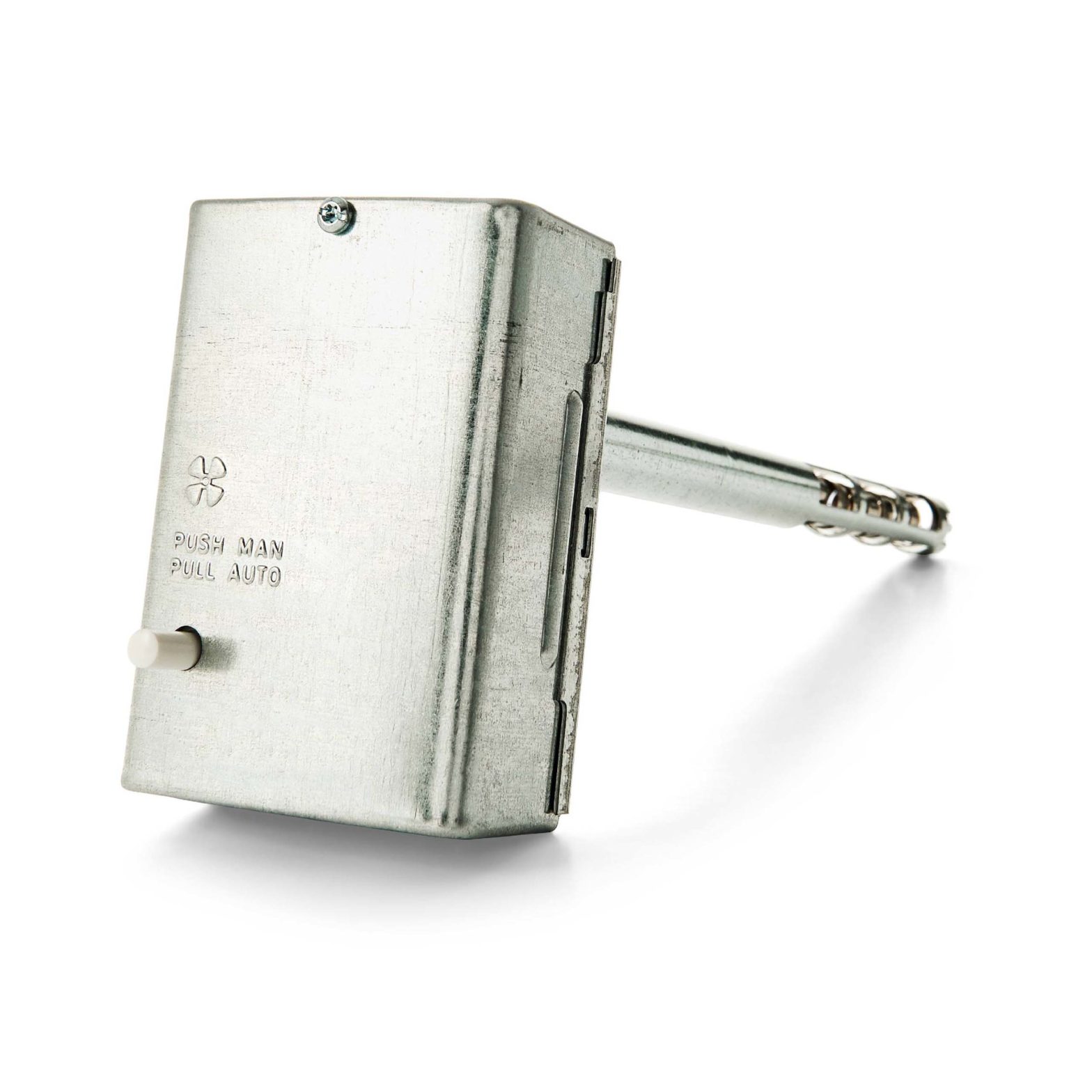
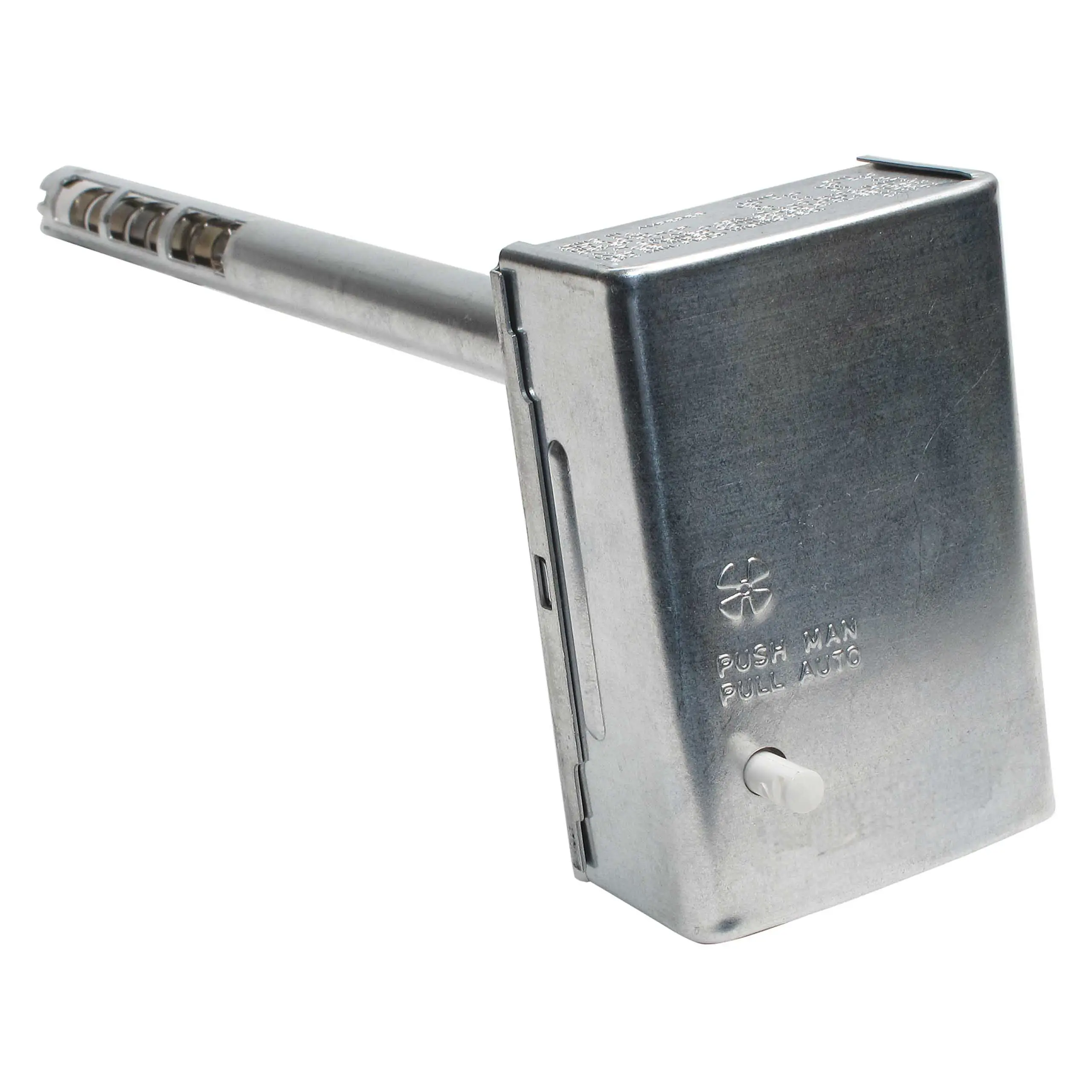
The L4064B controls the on and off operation of the heating unit’s fan motor and provides high limit control of the main burner. It is suitable for all types of forced air heating systems.The L4064B’s bimetal sensing element turns fan on and off according to plenum temperature.The L4064B has a manual switch to provide continuous fan operation, mounting adapters for replacing competitive devices, adapters for wiring convenience, and a strain relief bushing for protecting the wiring from damage due to field abuse.Limit contacts are suitable for line voltage, low voltage or millivoltage circuits.The fan-on timing can vary depending on applied voltage and switch ambient.
INSTALLATION
When installing this product…
1. Read these instructions carefully. Failure to follow them could damage the product or cause a hazardous condition.2. Check the ratings given in the instructions and on the product to make sure the product is suitable for your application.3. Installer must be a trained, experienced service technician.4. After installation is complete, check out product operation as provided in these instructions.
WARNING
Failure to remove brass jumper, if limit switch is in low voltage circuit, can cause electrical shock hazard or damage low voltage controls.
- Disconnect power supply before connecting wiring to prevent electrical shock or equipment damage.
- When connecting cable or conduit to control, avoid straining the control case.
Follow furnace or burner manufacturer’s instructions, if available. The L4064B has a maximum switch temperature of 190°F (88°C), maximum element temperature of 350°F (177°C). Do not exceed these temperatures or the following electrical ratings (amperes):
| 120 Vac | 240 Vac | |||
| FAN | LIMIT | FAN | LIMIT | |
| Full Load | 14 | 8 | 7 | 4 |
| Locked Rotor | 84 | 48 | 42 | 54 |
Pilot Duty: 2 A at 24 Vac; 0.25 A at 0.25 to 12 Vdc. Maximum Combined Connected Load: 2000 VA.75°C (167°F) (min.) field wiring required. Wiring must conform to NEC Class 1 requirements.
LOCATIONIf this is a replacement installation, locate the L4064 in the same location as the control being replaced. Sensing tube length should be same as old control. If this is a new installation, the element should be installed only by a trained, experienced service technician according to the furnace manufacturer’s instructions. The element must not touch any internal part of the furnace.
Note: The electrical rating is at maximum switch temperature of 190°F (88°C). If plenum surface temperature exceeds 190°F (88°C), heat insulating material or a mounting bracket must be used.
MOUNTING
The device may be mounted either on the plenum surface or with a bracket (rigid or swivel).
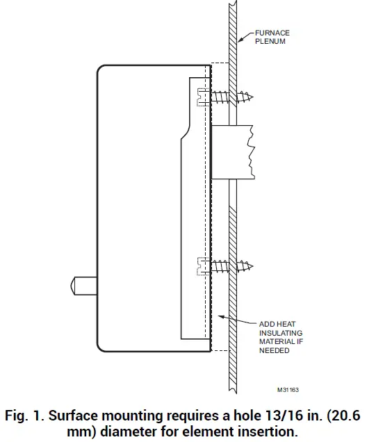
SURFACE MOUNTING
Hole in plenum should be just large enough to accommodate the 3/4 in. (19.1 mm) diameter element tube, Fig. 1. For adequate clearance, a 13/16 in. (20.6 mm) diameter hole is recommended.
- Remove cover by squeezing sides and pulling off. Insert element in plenum and mark location of mounting holes. Make sure the case is snug against the plenum before marking the mounting screws.
- Punch or drill holes for mounting screws.
- Place insulation between plenum and case if neces-sary.
- Fasten controller securely with mounting screws.
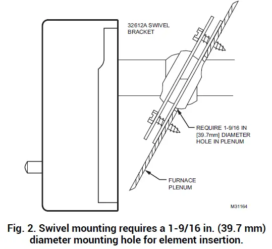
SWIVEL MOUNTING
L4064 may also be swivel-mounted. The swivel bracket requires a 1-9/16 in. (39.7 mm) hole in the plenum (Fig. 2).
- Use bracket as a template to mark the location of mounting holes in plenum. Drill or punch holes for mounting screws.
- Fasten the brackets in place with furnished screws. Start the screws but do not tighten.
- Insert element tube through bracket, straighten con-troller, and fasten. Tighten the mounting screws securely. It may be necessary to rotate the bracket to tighten all screws securely.

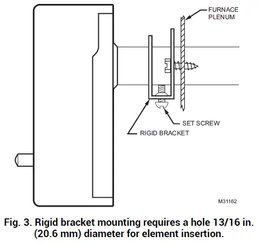
RIGID BRACKET MOUNTING
When mounting control on bracket, setscrew must strike tube frame not sensing element to prevent bypassing the safety limit function.L4064 may be mounted using a rigid bracket. The rigid bracket requires a hole 13/16 in. (20.6 mm) diameter for element insertion (Fig. 3).
- Use bracket as a template to mark the location of mounting holes in plenum. Drill or punch holes for mounting screws.
- Fasten bracket in place with furnished screws. Tighten the screws securely.
- Insert element tube through bracket, straighten con-troller and fasten by tightening setscrew. Be sure screw strikes tube frame and does not strike sensing element.
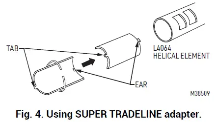
- For replacement installations with existing 1 in. (25.4 mm) diameter hole. SUPER TRADELINE models are supplied with split steel bushings and wire snap ring. Follow the instructions below for using the steel bushing adapter.
STEEL BUSHING ADAPTER
- Insert one-half of the split steel bushing (Fig. 4), through the wire ring. It may be necessary to spread the ring slightly.
- Insert the other half of the steel bushing into the ring making sure tabs and ears are at the same ends.
- Place bushing assembly on element, ear end first.
- Holding bushing at seams, push firmly to the control end of element.
- Insert element tube with adapter through bracket, straighten controller and fasten. Tighten setscrew. Be sure screw strikes bushing not coiled bimetal sensing element.
WIRING
Disconnect power supply before beginning installation to prevent electrical shock or equipment damage.All wiring must comply with local electrical codes and ordinances or in the absence of local codes with the National Electrical Code ANSI C1-1981-NFPA 70. Follow burner or furnace manufacturer’s instructions if available; otherwise, see Fig. 10 and proceed as follows.
IMPORTANT
The brass jumper is the breakaway type. It must be removed when the limit is used in the low voltage circuit. To remove jumper, break with a needlenose pliers and remove completely, Once removed, it is not replaceable. See Fig. 8 for location.
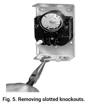
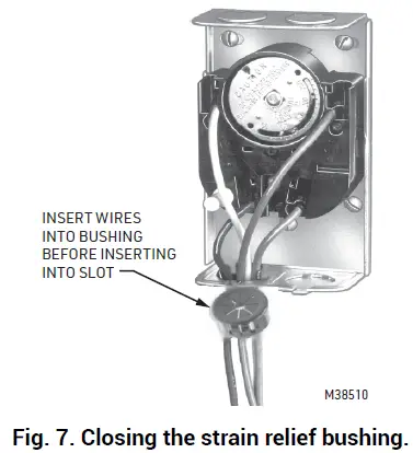
The slotted knockouts on the bottom of the case and the strain relief bushing are provided to simplify the installation procedure and to protect the wires.
- To remove the slotted knockout(s), use a needlenose pliers as shown in Fig. 5 and pull straight down.
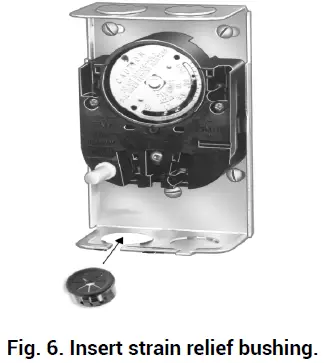
- If cable is used, we recommend using a strain relief bushing in the knockout (Fig. 6). Pass the wires through bushing before connecting.Refer to the following section for type of wiring con-nections (standard wire push-in terminals or female receptacle).
 Refer to the following section for type of wiring con-nections (standard wire push-in terminals or female receptacle).
WIRING CONNECTIONS
When connecting cable or conduit to this controller, use care to avoid strain on the control case.Connections can be made to standard wire push-in terminals or female receptacles for 1/4 in. (6.4 mm) male flag connectors on both the fan and limit switches (Fig. 8).FOR STANDARD WIRE PUSH-IN TERMINALSConnect wires to the terminals as follows:
- Use Nos. 14,16, or 18 solid wire or Nos. 14 or 16 stranded wire, depending on the electrical requirement.
- Strip insulation from wires the distance shown by the strip gauge on the controller.
- Solid wire may be inserted directly into the terminal holes. If the stranded wire is used, insert a small screwdriver into the slot next to the terminal. Push screw-driver in and hold while inserting wire into the terminal (Fig. 8). Remove screwdriver. If the stranded wire is sol-der-dipped, it can be pushed directly into terminal holes.
FOR FEMALE RECEPTACLESIt is recommended that the female receptacles be used for wiring accessory equipment; i.e., electronic air cleaner, humidifier, etc. Connect wires to the receptacles as follows:
- Use Nos. 14 to 18 size wire, depending on electrical requirement.
- Attach 1/4 in. (6.4 mm) male flag connector to each wire. Two male connectors with leadwires are sup-plied.
- Push male flag connector directly into the female receptacle. Make sure that the flag is forced to the bottom of cavity and wire is in the channel (Fig. 8).
IMPORTANT: Make certain all wires are clear of rotating scale-plate.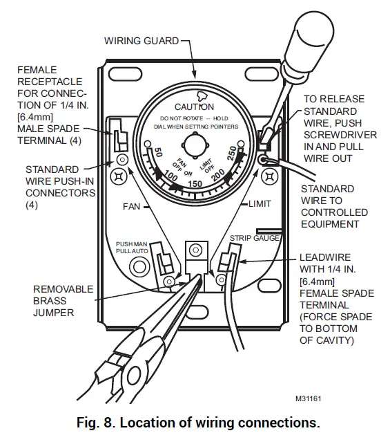 UNIVERSAL COMBINATION FAN AND LIMIT CONTROLLERS
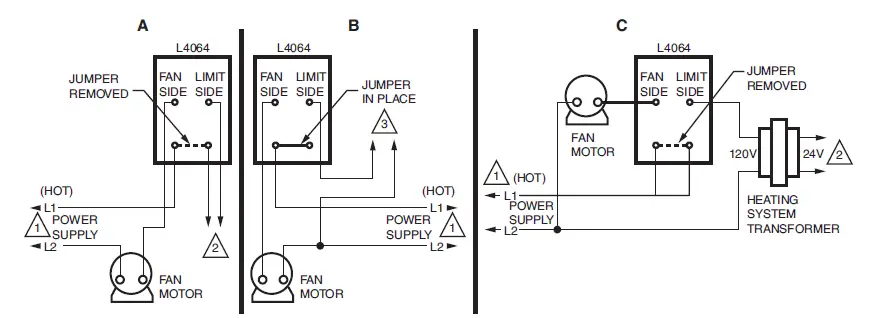
Fig. 9.A: Limit in low voltage circuit.B: Limit in line voltage circuit.C: Limit in line voltage circuit without jumper.
SETTINGS AND ADJUSTMENTS
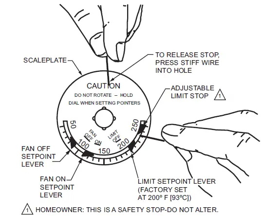
CAUTION: When adjusting the fan and limit set point levers (Fig. 10), hold the scalepale dial to keep it from turning and straining the sensing element. Move each indicator lever to the control point recommended by the burner or furnace manufacturer. Use gentle finger pressure.
FAN SETTING ADJUSTMENT
- Move the FAN OFF lever to the temperature at which the fan is to stop to prevent circulation of cool air.
- L4064B – Move the FAN ON lever to the temperature at which the fan is to come on.
MANUAL FAN SWITCHFor constant fan operation, push the FAN switch button in. For fan to cycle automatically, pull button out.LIMIT SETTING ADJUSTMENTThese controllers have a limit stop which prevents the limit indicator lever from being adjusted beyond the equipment manufacturer’s specifications.
- Push the small end of Limit Adjust Tool (196722) through hole in scaleplate (located at caution mark-ing) to depress the stop disc not more than 1/16 in. (1.6 mm) to release stop lock (Fig. 10). Stop disc is on back of scaleplate.
- While depressing the stop disc, insert the long end of Limit Adjust Tool next to limit stop (Fig. 10) and move the stop to desired setting. If the L4064 is a replace-ment control, high limit stop setting should be the same as that of the control being replaced. (Move stop clockwise to lower the setting, counterclockwise to raise it.) Then remove the limit stop adjust tool.
- Set the LIMIT OFF lever to the temperature at which the high limit switch is to open to stop the burner. If the high limit stop has been properly set, the LIMIT OFF lever should be as high as the stop permits.
OPERATIONAs the plenum temperature rises, the bimetal sensing element of the control wraps and mechanically makes the fan contacts (at the FAN ON temperature setting). During normal operation, the call for heat end before the LIMIT setting is reached, and the fan contacts break as the plenum temperature falls and the FAN OFF setting is reached. If the call for heat continues until the temperature in the plenum rises to the LIMIT setting, the bimetal element will mechanically break the limit contacts and de-energize the gas control circuit.
CHECKOUTWhen installation is complete, disconnect the fan motor circuit at the L4064. Turn on power and set thermostat to call for heat. Burner should come on and limit controller should shut burner off when plenum temperature reaches the limit set point. Turn off power, reconnect the fan switch, turn on power and again set thermostat to call for heat. Fan should come on when plenum temperature has reached fan-on setting.
Resideo Technologies, Inc.1985 Douglas Drive North, Golden Valley, MN 554221-800-468-150269-0117—04 M.S. Rev. 09-20 | Printed in United Stateswww.resideo.com
 report this ad
© 2020 Resideo Technologies, Inc. All rights reserved.This product is manufactured by Resideo Technologies, Inc. and its affiliates.
[xyz-ips snippet=”download-snippet”]