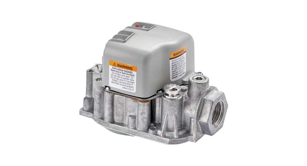

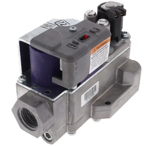
resideo VR9205Q Direct Ignition Combination 2 Stage Gas Controls
INSTALLATION INSTRUCTIONS
The VR9205Q Direct Ignition Combination 2-Stage Gas Controls are used in gas-fired appliances with up to 140 KBtu/h capacity at 1 in. wc pressure drop. They have been optimized for direct ignition applications and include a manual switch, two automatic operators and a pressure regulator. The valve may be used on either natural gas or LP gas applications.
- Valve capacities are shown in Table 1.
- For suffix letter designation, see Tables 2 and 3.
| Model | Size Inlet- Outlet (in.) | AGA Certified Capacity | AGA Certified Minimum
Regulationb |
AGA Certified Maximum Regulation |
| KBtu/h | KBtu/h | KBtu/h | ||
| VR9205 | 1/2 x 1/2 | 140 | 20 | 200 |
- Capacity based on 1000 Btu/ft3, 0.64 sp gr natural gas at 1 in. wc pressure drop (37.3 MJ/m3, 0.64 sp gr natural gas at 0.25 kPa pressure drop).
- Minimum regulation rated at high fire. Low fire regulation minimum based on outlet pressure is approximately 8 KBtu/h.
| Model Number Suffix Letter | Ambient Temperature Range | Pressure Regulator Type |
| Q | -40°F to 175°F (-40°C to +79°C) | Two-Stage |
SPECIFICATIONS
- Body Pattern: Straight through; see Table 1 for inlet and outlet size.
- Electrical Ratings:Voltage and Frequency: 24 Vac, 50/60 Hz.Current Draw: Low Stage energized, 0.4A; High Stage energized, 0.5A.
- 6 in. Wire Harness: 50045486-001.Gas valve end: Tyco Mate-N-Lok consisting of the following:Housing: Tyco 172166-1.Pins: Tyco 770904-1 or 770988-1.Control end: 3/8 in. stripped leads.
- Approvals:CSA Design Certificate # 158158
| Model Number Suffix Letter | Kit to Convert Natural Gas to LP | Kit to Convert LP to Natural Gas |
| Q | 50033841 | 50033842 |
PLANNING THE INSTALLATION
WARNING
Fire or Explosion Hazard.Can cause property damage, severe injury, or death.Follow these warnings exactly:
- Plan the installation as outlined below.
- Plan for frequent maintenance as described in the Maintenance section.
Heavy demands are made on the controls when direct ignition systems are used on central heating equipment in barns, greenhouses, and commercial properties and on heating appliances such as commercial cookers, agricultural equipment, industrial heating equipment and pool heaters.Special steps may be required to prevent nuisance shutdowns and control failure due to frequent cycling, severe environmental conditions related to moisture, corrosive chemicals, dust, or excessive heat. These applications require Resideo Residential Combustion Engineering review; contact your Resideo Sales Representative for assistance.Review the following conditions that can apply to your specific installation and follow the precautions suggested.
Frequent CyclingThis control is designed for use on appliances that typically cycle three to four times an hour only during the heating season. In year-round applications with greater cycling rates, the control can wear out more quickly. Perform a monthly checkout.
Water or Steam CleaningIf a control gets wet, replace it. If the appliance is likely to be cleaned with water or steam, protect (cover) the control and wiring from water or steam flow. Mount the control high enough above the bottom of the cabinet so it does not get wet during normal cleaning procedures.
High Humidity or Dripping WaterDripping water can cause the control to fail. Never install an appliance where water can drip on the control. In addition, high ambient humidity can cause the control to corrode and fail. If the appliance is in a humid atmosphere, make sure air circulation around the control is adequate to prevent condensation. Also, regularly check out the system.
Corrosive ChemicalsCorrosive chemicals can attack the control, eventually causing a failure. If chemicals are used for routine cleaning, avoid contact with the control. Where chemicals are suspended in air, as in some industrial or agricultural applications, protect the control with an enclosure.
Dust or Grease AccumulationHeavy accumulations of dust or grease can cause the control to malfunction. Where dust or grease can be a problem, provide covers for the control to limit contamination.
HeatExcessively high temperatures can damage the control. Make sure the maximum ambient temperature at the control does not exceed the rating of the control. If the appliance operates at very high temperatures, use insulation, shielding, and air circulation, as necessary, to protect the control. Proper insulation or shielding should be provided by the appliance manufacturer; verify proper air circulation is maintained when the appliance is installed.
INSTALLATION
When Installing this Product…
1. Read these instructions carefully. Failure to follow them could damage the product or cause a hazard-ous condition.2. Check the ratings given in the instructions and on the product to make sure the product is suitable for your application.3. Installer must be a trained, experienced service technician.4. After installation is complete, check out product operation as provided in these instructions.
Fire or Explosion Hazard.Can cause property damage, severe injury or death.Follow these warnings exactly:
- Disconnect power supply before wiring to prevent electrical shock or equipment damage.
- To avoid dangerous accumulation of fuel gas, turn off gas supply at the appliance service valve before starting installation, and perform Gas Leak Test after installation is complete.
- Always install a sediment trap in the gas supply line to prevent contamination of gas control.
- Do not force the on-off switch. Use only your fingers to operate the on-off switch. Never use any tools. If the electronic on-off switch does not operate by hand, the gas control should be replaced by a qualified service technician. Force or attempted repair may result in fire or explosion.
CAUTIONEquipment Damage Hazard. Can burn out thermostat or transformer. Applying a jumper across (or shorting) the valve coil terminals, even temporarily, can burn out the thermostat or transformer.Follow the appliance manufacturer’s instructions if available; otherwise use these instructions as a guide.IMPORTANTThese gas controls are shipped with protective seals over the inlet and outlet tappings. Do not remove the seals until ready to install adapters or connect the piping.
1. Always change the main orifices when converting from natural to LP gas or from LP to natural gas. Carefully follow appliance manufacturer’s specifications and instructions to assure proper appliance conversion.2. Gas controls are factory-set for natural or LP gas. Do not attempt to use a gas control set for natural gas on LP gas, or a gas control set for LP gas on natural gas.
INSTALL BUSHINGS TO CONTROL
If bushings are being installed on the control, mount them as follows:Bushings
1. Remove the seal over the control inlet or outlet.2. Apply a moderate amount of good quality pipe compound to the bushing, leaving two end threads bare. On an LP installation, use a compound that is resistant to LP gas. Do not use Teflon tape.3. Insert the bushing in the control and carefully thread the pipe into the bushing until tight.
Complete the instructions below for installing the piping, installing the control, and connecting the wiring. Make sure the leak test you perform on the control after completing the installation includes leak testing the bushings.
LOCATION
The gas controls are mounted in the appliance vestibule on the gas manifold. If this is a replacement application, mount the gas control in the same location as the old control.Locate the combination gas control where it cannot be affected by steam cleaning, high humidity, or dripping water, corrosive chemicals, dust or grease accumulation or excessive heat.To assure proper operation, follow these guidelines:
- Locate the gas control in a well-ventilated area.
- Mount the gas control high enough above cabinet bottom to avoid exposure to flooding or splashing water.
- Assure the ambient temperature does not exceed the ambient temperature ratings for each component.
- Cover the gas control if the appliance is cleaned with water, steam, or chemicals or to avoid dust and grease accumulation.
- Avoid locating the gas control where exposure to corrosive chemical fumes or dripping water are likely.
Install Piping to Control
All piping must comply with local codes and ordinances or with the National Fuel Gas Code (ANSI Z223.1, NFPA No. 54), whichever applies. Tubing installation must comply with approved standards and practices.
1. Use new, properly reamed pipe that is free from chips. If tubing is used, make sure the ends are square, deburred and clean. All tubing bends must be smooth and without deformation.2. Run pipe or tubing to the control. If tubing is used, obtain a tube-to-pipe coupling to connect the tub-ing to the control.3. Install a sediment trap in the supply line to the con-trol. See Fig. 1.
Install Control
- The gas valve may be mounted in any position.
- Mount so the gas flow is in the direction of the arrow on the bottom of the control.
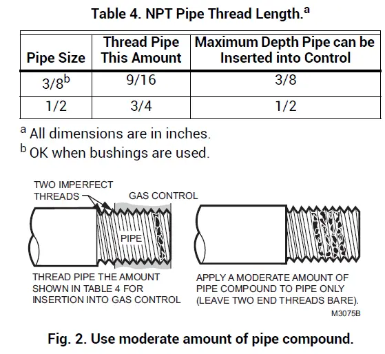
- Thread the pipe the amount shown in Table 4 for insertion into the control or adapters. Do not thread the pipe too far. Valve distortion or malfunction can result if the pipe is inserted too deeply.
- Apply a moderate amount of good quality pipe compound (do not use Teflon tape) only to the pipe, leaving two end threads bare. On LP installations, use a compound resistant to LP gas. See Fig. 2.
- Remove the seals over the control inlet and outlet if necessary.
- Connect the pipe to the control inlet and outlet. Use a wrench on the square end or a socket on the hex end of the control. See Fig. 3.

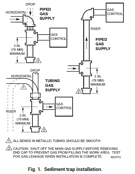
ALL BENDS IN METALLIC TUBING SHOULD BE SMOOTH.CAUTION: SHUT OFF THE MAIN GAS SUPPLY BEFORE REMOVING END CAP TO PREVENT GAS FROM FILLING THE WORK AREA. TEST FOR GAS LEAKAGE WHEN INSTALLATION IS COMPLETE.
| Pipe Size | Thread Pipe This Amount | Maximum Depth Pipe can be Inserted into Control |
| 3/8b | 9/16 | 3/8 |
| 1/2 | 3/4 | 1/2 |

WIRING
ELECTRICAL SHOCK HAZARD.Can cause severe injury, death or property damage.Disconnect the power supply before making wiring connections. More than one disconnect may be involved.
Follow the wiring instructions furnished by the appliance manufacturer, if available, or use the general instructions provided below. When these instructions differ from the appliance manufacturer’s, follow the appliance manufacturer’s instructions.All wiring must comply with applicable electrical codes and ordinances.
- Disconnect power supply before making wiring connections to prevent electrical shock or equipment damage.
- Check the power supply rating on the gas control and make sure it matches the available supply. Install a transformer and other controls as required.
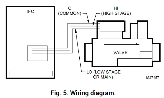
- Connect the control circuit to the gas control terminals. See Fig. 4 and 5 for typical terminal connections and wiring.
- Adjust thermostat heat anticipator to the rating stamped on valve operator.
CAUTIONEquipment damage.Can burn out valve coil terminals.Never apply a jumper across (or short) the valve coil terminals, even temporarily.
IMPORTANT: These gas controls are shipped with protective seals over the inlet and outlet tappings. Do not remove the seals until ready to install adapters or connect the piping.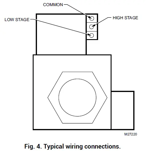
| Valve Pins | Typically Connects to (through Mini Mat-N–Loc) |
| Low Stage | Mv, Lo, Valve |
| High Stage | W2, Hi |
| Common | MV/Pv, Valve, Common |
STARTUP AND CHECKOUT
On-Off SwitchThe on-off switch settings are as follows:
- OFF: Prevents main gas flow through the control.
- ON: Permits gas to flow into the control body. Under control of the thermostat and direct ignition module, gas can flow to the main burners.
NOTE: Controls are shipped with the electronic on-off switch in the ON position.
Perform Gas Leak Test
Fire or Explosion Hazard. Can cause property damage, severe injury or death.Perform Gas Leak Test every time work is done on a gas system.
IMPORTANT: Do not spray soap and water solution on the gas control. Do not use an excessive amount of soap and water solution to perform the gas leak test. These can damage the control.
Gas Leak Test
1. Paint pipe connections upstream of the gas control with a rich soap and water solution. Bubbles indi-cate a gas leak.2. If a leak is detected, tighten the pipe connections.3. Light the main burner. Stand clear of the main burner while lighting to prevent injury caused from hidden leaks that could cause flashback in the appliance vestibule.4. With the main burner in operation, paint the pipe joints (including bushings) and the control inlet and outlet with rich soap and water solution.5. If another leak is detected, turn the gas control to off, tighten the joints and pipe connections.6. Replace the part if a leak cannot be stopped.
Turn On SystemPush the on-off switch to the ON position.Turn On Main BurnerFollow appliance manufacturer’s instructions or turn thermostat up to call for heat.
Check and Adjust Gas Input and Burner Ignition
- Do not exceed the input rating stamped on appliance nameplate, or manufacturer’s recom-mended burner orifice pressure for size of ori-fice(s) used. Make certain primary air supply to main burner is properly adjusted for complete combustion. Follow appliance manufacturer’s instructions.
- IF CHECKING GAS INPUT BY CLOCKING GAS METER: Make certain there is no gas flow through the meter other than to the appliance being checked. Other appliances must remain off with the pilots extinguished (or deduct their consumption from the meter reading). Convert flow rate to Btuh as described in form 70-2602, Gas Controls Handbook, and compare to Btuh input rating on appliance nameplate.
- IF CHECKING GAS INPUT WITH MANOMETER: Make sure the gas control is in the OFF position before removing outlet pressure tap plug to connect manometer (pressure gauge). Also move the gas control switch back to the OFF position when removing the gauge and replacing the plug. Before removing the inlet pressure tap plug, shut off gas supply at the manual valve in the gas piping to the appliance or, for LP, at the tank. Also, shut off gas supply before disconnecting manometer and replacing plug. Repeat Gas Leak Test at the plug with main burner operating.
NOTE: Check the inlet pressure before adjusting the pressure regulator.Two-stage VR9205 requires that you check and adjust both high and low-pressure regulator settings. Two-stage appliance’s operating sequences vary. Consult the appliance manufacturer’s instructions for the specific operating sequence and regulator adjustment procedure for the appliance in which the control was installed.
- Set appliance to operate on high.
- Carefully check the main burner lightoff. Make sure that the main burner lights smoothly and that all ports remain lighted.
- Check the full rate (high) manifold pressure listed on the appliance nameplate for high pressure. The gas control full rate outlet pressure should match this rating.
- With main burner operating, check the gas control flow rate using the meter clocking method or check pressure using a manometer connected to the out-let pressure tap on the control.
- If necessary, adjust the high pressure regulator to match the appliance rating. See Table 5 for fac-tory-set nominal outlet pressure and adjustment range.
- Remove the pressure regulator adjustment cap.
- Using a screwdriver, turn the inner adjustment screw for HI pressure clockwise to increase or counterclockwise to decrease the gas pressure to the burner.
- After high pressure has been checked, check low-pressure regulation. Two-stage appliance operating sequences vary. Consult the appliance manufacturer’s instructions for the specific operating sequence and regulator adjustment procedure for the appliance in which the control is installed and for instructions on how to prevent the control from moving to high stage while checking the low pres-sure regulator setting.
- Check the low rate manifold pressure listed on the appliance nameplate. Gas control low rate outlet pressure should match this rating.
- With main burner operating, check the gas control flow rate as before (using the meter clocking method or check pressure using a manometer connected to the outlet pressure tap on the control).
- If necessary, adjust the low pressure regulator to match the appliance rating. See Table 5 for fac-tory-set nominal outlet pressure and adjustment range.
- Remove the pressure regulator adjustment cap.
- Using a screwdriver, turn the inner adjustment screw for LO pressure clockwise to increase or counterclockwise to decrease the gas pressure to the burner.
- Once the high and low pressure have been checked and adjusted, replace the pressure regulator adjustment cap. If the desired outlet pressure or flow rate cannot be achieved by adjusting the gas control, check the gas control inlet pressure using a manometer at the inlet pressure tap of the gas control. If the inlet pressure is in the nominal range (see Table 5), replace the gas control. Otherwise, take the necessary steps to provide proper gas pressure to the control.
|
Model Type |
Type of Gas |
Nominal Inlet Pressure Range | Factory Set Nominal Outlet Pressure |
Adjustment Range |
|
Two- Stage |
NAT | 5.0-7.0 | 1.7 Low
3.5 High |
0.6–3.0 Low
3.0–5.0 High |
| LP | 12.0-14.0 | 4.9 Low
10.0 High |
2.5–7.0 Low
8.0–11.0 High |
Check Safety Shutdown Performance
Fire or Explosion Hazard.Can cause severe injury, death, or property damage.Perform the safety shutdown test any time work is done on a gas system.
NOTE: Read steps 1 through 7 before starting, and compare to the safety shutdown or safety lock-out tests recommended for the direct ignition (DI) module. Where different, use the procedure recommended for the module.
- Turn off gas supply.
- Set thermostat or controller above room tempera-ture to call for heat.
- Watch for ignition spark or for glow at hot surface igniter either immediately or following prepurge. See DI module specifications.
- Time the length of spark operation. See the DI module specifications.
- After the module locks out, enable the on-off switch and make sure no gas is flowing to the main burner.
- Set the thermostat below room temperature and wait one minute.
- Operate system through one complete cycle to make sure all controls operate properly.
MAINTENANCE
WARNINGFire or Explosion Hazard.Can cause property damage, severe injury, or death.
- Do not disassemble the gas control; it contains no replaceable components. Attempted disassembly, repair, or cleaning can damage the control, resulting in gas leakage.
- Regular preventive maintenance is important in applications in the commercial cooking and agricultural and industrial industries that place a heavy load on system controls because:
- In many such applications, particularly commercial cooking, the equipment operates 100,000 to 200,000 cycles per year. Such heavy cycling can wear out the gas control in one to two years.
- Exposure to water, dirt, chemicals and heat can damage the gas control and shut down the control system.
The maintenance program should include regular checkout of the control as outlined in the Startup and Checkout section, and the control system as described in the appliance manufacturer’s literature.Maintenance frequency must be determined individually for each application. Some considerations are:
- Cycling frequency. Appliances that may cycle 20,000 times annually should be checked monthly.
- Intermittent use. Appliances that are used seasonally should be checked before shutdown and again before the next use.
- Consequence of unexpected shutdown. Where the cost of an unexpected shutdown would be high, the system should be checked more often.
- Dusty, wet, or corrosive environments. Since these environments can cause the gas control to deteriorate more rapidly, the system should be checked more often.
The system should be replaced if:
- It does not perform properly on checkout or troubleshooting.
- The gas control is likely to have operated for more than 200,000 cycles.
- The control is wet or looks as if it has been wet.
SERVICE
WARNINGFire or Explosion Hazard.Can cause severe injury, death, or property damage.Do not disassemble the gas control; it contains no replaceable components. Attempted disassembly, repair, or cleaning can damage the control, resulting in gas leakage.
If Main Burner Does Not Come On With Call For Heat
1. Confirm the gas control knob is in the ON position.2. Adjust thermostat several degrees above room temperature.3. Using AC voltmeter, measure across terminals C and Low at the gas control. See Fig. 4 for terminal location.4. If voltage is incorrect or not present, check control circuit for proper operation.5. If proper voltage is present, replace gas control.
INSTRUCTIONS TO THE HOMEOWNER
Fire or Explosion Hazard.Can cause property damage, severe injury, or death.Follow these warnings exactly:
- Before lighting, smell around the appliance for gas. Be sure to smell next to the floor because LP gas is heavier than air. If you smell gas:a. Turn off the gas supply at the appliance service valve. On LP gas systems, turn off the gas supply at the gas tank.b. Do not light any appliances in the house.c. Do not touch electrical switches or use the phone.d. Leave the building and use a neighbor’s phone to call your gas supplier.e. If you cannot reach your gas supplier, call the fire department.
- Replace the gas control in the event of any physical damage, tampering, bent terminals, missing or broken parts, stripped threads, or evidence of exposure to heat.
IMPORTANT: Follow the operating instructions provided by the heating appliance manufacturer. The infor-mation below describes a typical control appli-cation, but the specific controls used and the procedures outlined in your appliance manufac-turer’s instructions can differ, requiring special instructions.
To Turn ON ApplianceSTOP! Read the Warnings Above Before Proceeding.
1. The lighting sequence on this appliance is automatic; do not attempt to manually light the main burner.2. If the furnace does not come on when the thermostat is set several degrees above room temperature, set the thermostat to its lowest setting to reset the safety control.3. Remove the burner access panel if provided on your appliance.4. Push the on-off switch to the OFF position.5. Wait five minutes to allow any gas in the combustion chamber to vent. Then if you smell gas, STOP! Follow Step 1 in the Warning above. If you do not smell gas, continue with the next step.6. If you do not smell gas, push the electronic on-off switch to the ON position.7. Replace the burner access panel.8. Reset the thermostat to the desired temperature.9. If the appliance does not turn on, turn the gas control knob to OFF and contact a qualified service technician for assistance.
Turning Off the Appliance
Vacation ShutdownSet the thermostat to the desired room temperature while you are away.Complete Shutdown
1. Turn off power to the appliance.2. Turn off the gas supply to the appliance.3. Push the on-off switch to the OFF position. Appliance will completely shut off.4. Follow the procedure in the Instructions to the Homeowner section above to resume normal operation.
 report this ad
© 2020 Resideo Technologies, Inc. All rights reserved.This product is manufactured by Resideo Technologies, Inc. and its affiliates.Resideo Technologies, Inc.1985 Douglas Drive North, Golden Valley, MN 554221-800-468-150269-2143EF—03 M.S. Rev. 10-20 | Printed in United Stateswww.resideo.com
References
[xyz-ips snippet=”download-snippet”]