![]()
![]()
User’s Manual Electric Bike
Name of Pedal ElectricAssistance Bicycle Components
![]()
| 1. Tire/Tube2. Rim3. Spoke4. Disc brake5. Fork6. Mudguard7. Front light8. Head tube9. Stem10. Display Panel11. Saddle | 12. Seat Post13. Frame14. Pedals15. Chainwheel/Crankset16. Chain17. Rear Light18. Kickstand19. Hub Motor20. Rear Carrier21. Battery |
Congratulations on your purchase of this Retrospec electric bike. It has been carefully designed and manufactured according to the latest international quality standards.Please read this instruction manual carefully and thoroughly before riding. It contains important information on safety, and maintenance. It is the owner’s responsibility to read this manual before riding. Keep this manual for future reference. This user’s instruction manual includes two sections:
SECTION I – Mechanical Operation, and SECTION II – the Electric Operation.These instructions apply to electric bike models with following equipment:
Section I: Mechanical Components Operation
- Disc Brakes
Section II: Electrical Components Operation
- Battery-pack behind the seat tube
- Rear hub motor
- Controller integrated to the battery-pack
- Handlebar-mounted Display Panel operations.
Warranty: Should any original component prove defective in terms of workmanship within its warranty period, we will replace it. Warranty period for Retrospec electric bikes is as follows:
Electrical Components excluding Battery: 2 years with proper maintenanceBattery: 1 yearFrame and Fork: 1 yearAll other components: 6 months
This warranty does not include labor and transportation charges. The company cannot accept any responsibility for consequential or special damage. This warranty applies only to the original retail purchaser who must have a proof of purchase in order to validate any claim. This warranty applies only in the case of defective components and does not cover the effects of normal wear, nor damage caused by accident, abuse, excessive loads, neglect, improper assembly, improper maintenance or the addition of any item inconsistent with the original intended use of the bicycle.
No bicycle is indestructible and no claims can be accepted for damage caused by improper use, competition use, stunt riding, ramp jumping and leaping or similar activities. Claims must be submitted through your retailer. Your statutory rights are not affected. The company reserves the right to change any specification without notice. All information and specifications within this manual are correct at time of printing.
Section I – Mechanical Components Operation, Maintenance, & Safety
Contents:
- Conditions for Riding This Electric bicycle
- Safe Cycling and Safety Tips
- Routine Maintenance Check and Lubrication
- Assembly Instructions
- Riding ConditionsThis pedal electric assistance bicycle is designed for riding on road, or paved surfaces where the tires have firm contact with the riding surface. This e-bike must be properly maintained according to the instructions found within this manual. The maximum weight of the rider and load is 220lbs (100kgs).
 WARNING! The owner/rider assumes the risk for personal injury, damage, or losses. If the conditions in this manual are breached, the warranty will be void automatically.
 -
Safe Cycling and Safety Tips
- Pre-Ride Check Points Before you ride your pedal electric assistance bicycle always make sure it is in a safe operating condition. Particularly check that your:• Nuts, bolts, quick-release and parts are fastened tight, not worn, or damaged.• Riding position is comfortable and unencumbered.• Brakes are operating effectively.• Steering is free with no excessive play.• Wheels run true and hub bearings are correctly adjusted.• Wheels are properly secured and locked to frame/fork.• Tires are in good condition and inflated to correct pressure (tire pressure in on tire sidewall – do not exceed max tire pressure).• Pedals are securely tightened to pedal cranks.• All reflectors are in position and secure.After you have made any adjustment to your electric bicycle, check that all nuts and bolts are securely tightened and cables are free from kinks and fixed securely to the electric bicycles frame. Every six months, your electric bicycle should be professionally checked to ensure that it is in correct and safe working order. It is the responsibility of the rider to ensure all parts are in good working order.
- What Never To Do When Riding• NEVER ride without wearing an approved helmet, which must meet USA/European (CPSC/EN) standards. Always comply with the local laws and ordinances.• NEVER ride on the same side of the road as oncoming traffic.• NEVER carry a passenger, this bicycle is designed for a single rider only.• NEVER hang item(s) over the handlebars, this could interfere with steering or catch in the front wheel causing a crash.• NEVER hold on to another motor vehicle or bicycle.• NEVER ride too close to another vehicle – keep your distance and awareness.WARNING! Wet Weather Riding: Your bike’s brakes do not work as well under wet or icy conditions as they do under dry conditions.The braking distance in wet weather will be longer than that in dry conditions. Take special precautions in wet weather to assure safe stopping. Ride slower than normal and apply your brakes well in advance of anticipated stops.WARNING! Night Riding: Do not ride at night. If you have to be on your e-bike at night or in low-light conditions, always comply with laws and regulations (local and otherwise) for bicycle lighting. Use approved headlights (white), taillights (red) properly affixed to your e-bike in addition to all-around reflectors. For additional safety, wear light colored clothing with reflective stripes, or safety yellow or safety orange clothing. Check that the reflectors are firmly secured in the correct position and clean and not obscured. Damaged reflectors must be replaced immediately.
Routine Maintenance Check and Lubrication
![]() WARNING! As with all mechanical components, your bicycle is subjected to wear and stress. Different materials and components may react to wear or fatigue in different ways. If the design life of a component has been exceeded it may suddenly fail, possibly causing injuries to the rider. Any types of cracks, scratches, or change of coloring in highly stressed areas indicate that the life of the component has been reached and it should be replaced immediately. Always inspect your bicycle before every ride.
WARNING! As with all mechanical components, your bicycle is subjected to wear and stress. Different materials and components may react to wear or fatigue in different ways. If the design life of a component has been exceeded it may suddenly fail, possibly causing injuries to the rider. Any types of cracks, scratches, or change of coloring in highly stressed areas indicate that the life of the component has been reached and it should be replaced immediately. Always inspect your bicycle before every ride.![]() WARNING! Use only genuine replacement parts, particularly for safety-critical components, installed by a professional bicycle mechanic. To keep your electric bicycle functioning well, the following routine maintenance lubrication is necessary.
WARNING! Use only genuine replacement parts, particularly for safety-critical components, installed by a professional bicycle mechanic. To keep your electric bicycle functioning well, the following routine maintenance lubrication is necessary.![]() Half-Yearly: Remove, clean, and lubricate chain and all cables. Check and replace as required.Weekly (or as needed): Wash bicycle with warm soapy water. Dry with a soft, nonabrasive cloth. Do not use strong chemicals or abrasives. Do not use a high-pressure washer. Inspect your bicycle while cleaning.
Half-Yearly: Remove, clean, and lubricate chain and all cables. Check and replace as required.Weekly (or as needed): Wash bicycle with warm soapy water. Dry with a soft, nonabrasive cloth. Do not use strong chemicals or abrasives. Do not use a high-pressure washer. Inspect your bicycle while cleaning.
| 1- TiresCheck for cuts and wear. Maintain pressure indicated on tires sidewall for maximum efficiency and safety. | 7/17- Front/Rear LightCheck the lights are in good working condition, no cracks in the lens, replace if necessary. | 15- CranksCheck weekly. Remove, clean, and lubricate half-yearly. |
| 2/3- WheelsCheck that axles are sealed, spin smoothly, and are secured properly. Check rims are straight. Check for loose or damaged spokes. | 9- Headset/Stem AssemblyRemove, clean, and regrease yearly, replace parts, bearings as if worn, or as necessary. | 16-ChainCheck and lightly lubricate weekly. Clean and lubricate half-yearly (minimum). |
| 4-BrakesLightly oil exposed cables monthly. Check the rotors are straight and secured to the hub. Make sure there are no oils on the rotors. Maintain and replace brake caliper pads when worn, brake cables when frayed. | Electrical Parts: #10, 19, & 21. Refer toSection II of this manual. | 18-KickstandCheck the attaching bolt is tight, and the kickstand is secure in its stowed position for riding. Replace if necessary. |
| 5- ForkDealer adjustment only | 11-Saddle and Quick-ReleaseCheck the quick release is tight and the saddle does not move, ensure the saddle and quick-release are undamaged, replace if necessary. | 20-Rear CarrierCheck the paint for cracks which couldindicate material fractures. |
| 6-MudguardsCheck they are securely tight, clean, and not damaged. Replace if necessary. | 14-PedalsLightly oil bearings monthly. |
![]() WARNING! Every six months, your pedal electric assistance bicycle should be professionally checked to ensure that it is in correct and safe working order. It is the responsibility of the rider to ensure all parts are in working order prior to riding.
WARNING! Every six months, your pedal electric assistance bicycle should be professionally checked to ensure that it is in correct and safe working order. It is the responsibility of the rider to ensure all parts are in working order prior to riding.
Assembly Instruction
This bikes comes assembled- no tools required for assembly. We strongly recommend you take this bike to a professional bicycle shop for adjustment and education on its operation and maintenance.Unfolding Your Bike And Connecting The Frame1. Your bike comes folded. Unfold the frame and swing the two hinged halves until they almost come together – this may require extra effort as the parts are new.2. You will need to pull up on the quick release latch (Fig. 3) to allow the two frame halves to mate against one another.3. Once the halves are together, release the quick release latch so it locks (Fig.4).4. Swing the quick release latch around so it fits fully in the slot in the hinge on the front half of the frame. Make sure the steel and nylon washers are on the outside of the hinge and against the lever body (Fig.5)5. Close the quick release lever to complete attaching the two halves of the frame (Fig.6 & 7). The lever should require some effort to close. If the lever is too difficult to close, or closes with little effort, tighten or loosen the nut on the end of the latch to adjust the lever tension (Fig.5).![]()
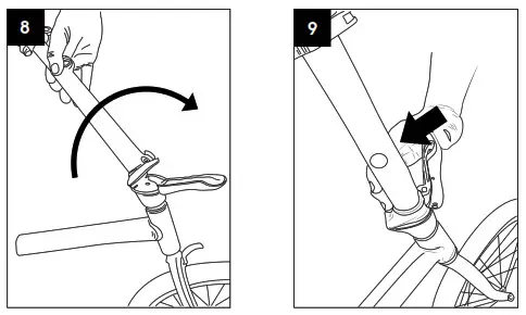
Connecting The Handlebar To The Stem
- Swing the handlebar assembly into place by rotating upwards (Fig.8).
- Once the handlebars are in the upright position, lock into place by pressing the lever to the handlebar mast (Fig
Unfold Pedals
- Unfold the pedals by simply applying pressure to pull them in the riding position. You will hear a click when they lock into position. (Fig. 10 & 11)
Check Pedal Tightness
- Pedals need to be checked for tightness.
- Use the 15mm portion of the included multi-wrench, your own 15mm open end wrench, or adjustable wrench.
- The right side pedal tightens clockwise (Fig.12). The left side pedal tightens counterclockwise (Fig.13). The pedals need to be tightened with a considerable amount of force so that they do not come lose. Pedal side is determined when you sit on bike.
Adjust Seat Height
- To adjust the seat height, pull the quick release lever attached to the top of the seat tube outwards and adjust the seat to your desired height.
- Once you have adjusted the seat post to your desired height, lock it in place by closing the quick release lever against the clamp (Fig.14). The lever should require some force to close. If it closes too easily and does not hold or if the effort to close the clamp is too great, adjust the clamping force by loosening or tightening the adjusting nut on the side opposite the lever.
IMPORTANT! Your seat post is extra-long to fit a variety of rider sizes to the compact, folding frame design. Check the seat post closely. It has upper limit line marked on rear of seatpost (how low your seat can go), and lower limit line (how high your seat can go) marked on the front of the seatpost.
Lower Limit Line: Never adjust the seat height so that the limit line at the lower end of the seat post is showing outside of the frame (Fig.15). Upper Limit Line: Always adjust the seat height so that the limit line at the upper end of the seat post is showing outside of the frame (Fig.16).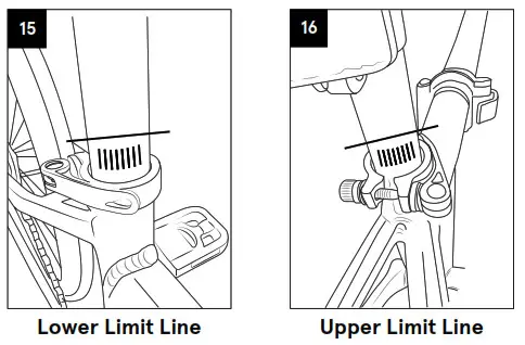
![]() WARNING! Using the bike with the minimum insertion line on the lower portion of the seat post showing above the frame could result in a failure of the seat post and/or the frame causing a loss of control with potential injury to rider. Such failures are not covered by warranty as it is improper use of the product.
WARNING! Using the bike with the minimum insertion line on the lower portion of the seat post showing above the frame could result in a failure of the seat post and/or the frame causing a loss of control with potential injury to rider. Such failures are not covered by warranty as it is improper use of the product.
Check Tire Inflation & Installation
- Locate the tire manufacturer’s recommended inflation pressure found on the tire sidewall (listed as “PSI”).
- Using a hand or floor pump with a gauge, begin to inflate the tire to half its recommended inflation pressure and check to see that the tire is properly seated on the rim. Be sure to inspect both sides of the tire for proper fit.
- If the tire is seated unevenly or bulges out along the rim, let some air out of the tire and reposition the tire by hand so that it sits evenly on the rim.
- Continue to inflate the tire to the manufacturer’s recommended pressure.
- Do not exceed the recommended pressure as this will cause an unsafe condition potentially causing the tire to unexpectedly explode.
- Do not use a compressed air device to inflate your tires as the rapid inflation of the tire can cause it to blow off the rim.
- Tires and tubes are not warranted against damage caused by over-inflation or punctures from road hazards.
Check Handlebar Stem Alignment
- Sit on your bike – check to make sure the handlebar stem and fork are in-line with one another.
- If it is all good (Fig.20), you are done. Otherwise, do the following:A- Unfold the handlebar (Fig.17).B – With 5mm hex wrench loosen the Compression Cap the top center bolt in the stem (Fig.18).C With the same 5mm hex wrench, loosen the two Stem Binder Bolts on side of stem these hold the stem to the fork. Loosen just enough so you can move/adjust the stem and center it in line with the front tire (Fig.19).D Line up the handlebar/stem with the front tire (Fig.20).E Reverse the process:1. Tighten the top center bolt in the Compression cap of the stem (Fig.18).2. Tighten the two Stem Binder Bolts on the side of the stem (Fig.19).
Adjust Handlebar Height
- To adjust the handlebar height, pull the quick release lever attached to the top of the stem mast outwards and adjust the handlebar to your desired height.
- Once you have adjusted the handlebar to your desired height, lock it in place by closing the quick release lever against the clamp (Fig.21). The lever should require some force to close. If it closes too easily and does not hold the seat post in place, or if the effort to close the clamp is too great, adjust the clamping force by loosening or tightening the adjusting nut on the side opposite the lever.
IMPORTANT! Never adjust the handlebar height so that the limit line at the lower end of the seat post is showing outside of the frame (Fig.21).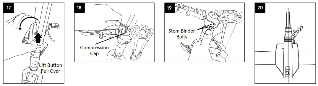 Before Your First RideWe strongly recommend you take your bike to a professional bike shop and have them check your work and fine tune the bike to ensure your bike is safe to ride.
Serial NumberIt is important that you locate and record the serial number of your bicycle in case of a recall or if the bicycle is stolen. The serial number can be found under the crank bottom bracket stamped into the frame (Fig.22).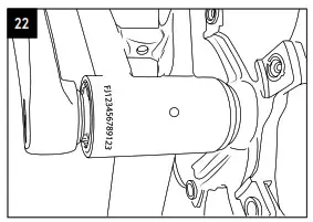 Section II- Electrical Components Operation, Maintenance, & SafetyThe e-bike in this manual features “Start Aid”. This electric assistance system will help riders save their energy when starting the bike rolling.
How Start Aid Works: When pressing the Start Aid button, the bike can be started at a speed of ~3.5MPH (6km/h). When the bike starts moving forward, start to pedal and release the “Start Aid” button.
Note: You can pedal one crank revolution to start the motor without using the “Start Aid “button.
Contents:
- Important System Caution notices
- Operation
- Battery Installation & Usage
- LCD Function Indicators
- Using and Maintaining the Battery
- Using and Maintaining the Battery Charger
- Using and Maintaining the Electric Hub Motor
- Maintaining the Controller
- Maintaining the Power-off Control of the Brake Lever
- Simple Troubleshooting
- Electrical Circuit Diagram and Specifications
- Main Technical Specification Sheet
Important Safety Precautions
• We strongly advise wearing an approved helmet which meets local safety standards.• Obey local traffic rules when riding on public roads.• Be aware of traffic conditions.• The rider must be over 14 years old.• Have your bike serviced only by authorized bicycle shops.• Regular servicing will ensure a better performance and a safe riding experience.• Do not exceed more than 220lbs (100kgs) on bicycle, including the rider and cargo.• Never have more than one rider on the bicycle.• Follow the regular maintenance schedule in this owner’s manual.• Do not open or attempt maintenance on any electrical components yourself. Contact your local bicycle specialist for qualified service when needed.• Never jump, race, perform stunts, or abuse your bicycle.• Never ride under the influence of intoxicating drugs or alcohol.• Do not ride at night. If riding at night, low-light, or poor weather conditions is unavoidable, we strongly recommend using front & rear lights, reflectors, and bright, safety clothing.• Wash with mild soapy water. Dry immediately with a soft, non-abrasive cloth.• Do not use strong chemicals or abrasives.![]() WARNING! Do not direct water spray at hubs, bearings, and electrical components and NEVER use a high-pressure washer – these actions may damage electrical components and bearings (bottom bracket, hubs, headset).
WARNING! Do not direct water spray at hubs, bearings, and electrical components and NEVER use a high-pressure washer – these actions may damage electrical components and bearings (bottom bracket, hubs, headset).
Operation
Your new electric assistance bicycle is a revolutionary means of transport, using an aluminum frame, Li-Ion battery, a super high efficiency electric hub motor, and controller with electric pedal assistance system, to support normal pedaling. These components will ensure safe riding with excellent function and performance. It is important for you to note the following guidelines to ensure getting the best possible experience from your electric bicycle.
- Always check your bicycle before riding.
- Before riding, check that the tires are fully inflated as indicated on the tire sidewall.Remember, performance of the bike and battery range is directly related to the weight of the rider and baggage/load, together with the stored energy in the battery. Battery range/performance can vary significantly based on terrain, load, & weather conditions.
- Charge overnight, prior to riding the next day.
- Clean and apply chain lube periodically as needed. With a soft rag or towel, wipe off excess lube. Clean and lubricate half-yearly (minimum).
Battery Installation & Usage.
Retrospec Jax Rev 500W & 750W have the battery positioned on the rear of the frame seat tube (Fig 2).The battery box bottom is fixed on bottom of the frame seat tube by screws (Fig 2.1).Then the battery case is locked by the key – see the operation details below.
- Insert and slide the Battery Pack vertically into the Battery/Controller Housing with the indicator facing up (Fig. 3), then slowly and firmly push it into place for a snug fit.
- Make sure the Battery Pack is firmly pushed into the Battery/Controller Housing and the connector is securely inserted inside the controller box.
NOTE: Battery Lock (Fig 4.2)
From the initial 12 o’clock position (battery and carrier are unlocked), insert the key into the key slot, press and turn it clockwise to 6 o’clock position (battery now locked into the housing). Reverse steps to unlock.
Battery ChargingYou can charge your battery while installed on the bike or removed for remote charging. If your bike is near an AC outlet, you can charge it with your bike’s battery still installed. The charging port is covered by a plastic cap (Fig 4.3).Alternatively, you can remove the battery for charging. This feature is useful in small areas where the bike will not fit or AC power supply is not near the bike. Following the steps above, make sure the battery is unlocked before removal. Make sure the switch is off and remember to keep your key secure!
![]() WARNING! Use only the charger provided with the electric bike, otherwise damage could occur to your battery and void the warranty. When charging, both battery and charger should be minimum 4 in (10cm) away from the wall, and in a cool, ventilated environment. Place nothing around the charger while in use!
WARNING! Use only the charger provided with the electric bike, otherwise damage could occur to your battery and void the warranty. When charging, both battery and charger should be minimum 4 in (10cm) away from the wall, and in a cool, ventilated environment. Place nothing around the charger while in use!
LCD and Function
Our KD58C Display Panel provides control of functions to fit the users needs. The Display Panel indicates the following:
- Smart Battery
- Power Assistance-Level
- Speed indication (current speed, max speed, and average speed)
- Motor-Output
- Trip Time
- Trip Distance and Total Distance
- Push-Assistance Function
- Error Code Indicator
Button DefinitionThe KD58C Display Panel has 3 buttons (M, +, -) which represent the functions M/MODE, +/UP, & -/DOWN.
Display Panel Functions and Indicators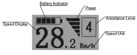
General OperationSwitching your E-Bike On/OffSwitching ON: Hold the MODE button for 2s.Switching OFF: Hold the MODE button for 2s again.In the OFF position system current “leakage” is less than 1 uA.When parking your bike for more than 10 minutes, the system switches off automatically.
Display InterfaceAfter switching on the E-Bike system, the display shows Running Speed. Once you’re riding, to change the displayed information, press MODE to cycle through the functions as below:Running Speed (Km/h) Trip Distance (Km) Trip Time (Hour) Average Speed (Km/h) Max Speed (Km/h). Each function will display for 2 seconds and then automatically returns to the Running Speed interface. When stopped and speed reads 0 mph (km/h), Total Distance will be added to the circulation interface.
The circulation interface of the condition that the speed is 0 mph (km/h)
Switching Smart-Aid Push-Assistance Mode On/OffTo access the push-assistance mode, hold the DOWN button for 2s, the E-Bike will go on at a uniform speed of 6 Km/h, “P” is shown on the screen at the same time. The push-assistance function switches off as soon as you release the DOWN button. Start-Aid Push-Assistance function may only be used when pushing the E-Bike. Danger of injury when the wheels of the E-Bike do not have ground contact while using the push-assistance function.
Assistance Level SelectionAssistance levels indicate the output power of the motor. The default value is level “1”. The default power ranges from level “0” to level “5”. Output power is zero on Level “0”. Level “1” is the minimum power. Level “5” is the maximum power.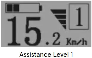
Power IndicatorThe output power of the motor will be indicated by the display – below:Error Code IndicationIf there are errors about the electronic control system, the ERR/error code will appear automatically.Contact your Dealer or Customer Service when an error code appears on the Display Panel.
Using and Maintaining the Battery
- Advantages of Lithium Batteries Your electric bicycle is equipped with high-quality lithium batteries which are a green energy source with reduced environmental impact and have the additional advantages of:• Charging without “memory” effect• Large energy capacity and output, small volume, light weight, suitable for high power• Long life• Wide temperature working range of: 14F-104F (-10°C to +40°C)
- Using and Maintaining the BatteryFor long battery life and to protect it from damage, use and maintain it following the guideline below:• While riding, periodically check your battery charge level on your handlebar mounted Display Panel. If you notice the battery charge is 5% or less, charge immediately!• Make sure you have a full charge before taking a long trip.• To check the battery charge on the battery itself: Press the button on the end of the battery case.• All 5 lights all blue color – battery is fully charged.• If, for example, only 2 lights, charge promptly. (Fig. 5.2)• If the bike is ridden infrequently, or stored long term, it must be fully charged every 2-3 months.WARNING! As mentioned above, long term storage, without periodic charging may reduce battery life.• Never use any metals to directly connect the two poles of the battery, otherwise, the battery will be damaged due to short circuit, and warranty voided.• Never put the battery near to fire or heat source.• Never strongly shake, slam/drop, or throw the battery – damage is likely.• When the battery pack is removed from the bike, always keep it out of reach of children to avoid and reduce the chance of accidents.• Do NOT disassemble the battery – never.
IMPORTANT! Always read the owner’s manual before charging the battery!IMPORTANT! Read the following points about the battery charger.
Using and Maintaining the Battery Charger
- Do not use this charger in an environment of gas and corrosive substances.
- Never strongly shake, slam/drop, or throw the battery – damage is likely.
- Always protect the battery charger from rain and moisture!
- Ideal operating temperature for the battery charger is: 14F-104F (-10°C to +40°C).
- Do NOT disassemble the battery charger – never.
- Use only the charger provided with your electric bike. Otherwise damage could occur to your battery, battery charger, and void the warranty.
- When charging, both battery and charger should be minimum 4 in (10cm) away from the wall, and in a cool, well ventilated environment. Place nothing around or on the charger, while in use!
Procedure for ChargingCharge the bike battery according to the following procedure:
- When charging the battery by AC (house/wall plug), it is not necessary to be on.
- Securely insert the charger output plug into the battery, then plug the main cable of the charger into a reachable AC (wall plug) outlet.
- During charging, the LED on the charger pack will be RED showing charging is in process. When the light on the charging pack turns GREEN, charging is complete.
- Upon full charge (GREEN light), FIRST disconnect the charger pack from the AC (wall plug); SECOND disconnect the charger output plug from the battery pack. FINALLY, close the charging socket cover on the battery – make sure it is securely closed.
Using and Maintaining the Electric Hub Motor.
Retrospec intelligent e-bikes are programmed to start with the electric assistance (“Start-Aid”) after a rotation of the pedals (crankset).
- Do not use this bike in flood waters, heavy rain.
- Do not immerse, submerge the electric parts in water – damage will likely happen.
- Avoid impacts to the hub motor, the aluminum alloy hub cover may break.
- Regularly check the screws on both sides of the hub motor; tighten them as necessary even if they are only a bit loose.
- It is necessary to periodically check the cable connection to the motor.
Maintaining the Controller.
Retrospec e-bikes have the Controller (the e-bike “brain”), positioned at the bottom and inside the battery pack holder/housing. The Controller is a critical component for your e-bike system. It is very important to follow the care guidelines below:Do not immerse, submerge the electric parts in water – damage will likely happen.
NOTE: If you think water may have got into the control box, switch-off the power immediately and pedal without electric assistance. You can pedal with electric assistance as soon as the controller has dried out.As with the battery, hub, display and other electrical parts – Never strongly shake, slam/drop, or throw the Controller – damage is likely.As with the battery, the best operating temperatures for the controller is: 5F-104F (-15°C to +40°C).The controller should be used in normal working temperature range from -15°C to +40°C
![]() WARNING! NEVER open the controller box. Any attempt to open the controller box, modify or adjust the controller will void the warranty. Please ask your local dealer or authorized service specialist to repair your bike.
WARNING! NEVER open the controller box. Any attempt to open the controller box, modify or adjust the controller will void the warranty. Please ask your local dealer or authorized service specialist to repair your bike.
Maintaining the Power-Off Control of the Brake Lever
This is a very important component for safe riding. Pay close attention to protect it from impact and damage. Regularly check that it is securely fastened to the handlebar.
Simple Troubleshooting
The information below is for diagnosing problems only. It is not a recommendation for the user to carry-out repairs. Any remedy outlined must be carried out by a professional e-bike repair person who is educated on the safety issues with bikes & e-bikes.
| Trouble Description | Possible Causes | Trouble Shooting |
| After the main battery switched on, the motor does not generate assistance when pedaling | 1) the motor cable is loose 2) brake lever did not return well, which keeps the switch in “power off” position 3/battery fuse is broken dl the speed sensor is too far away from the magnetic ring on the BA:Lexie 5) the connection between the sensor and the controller is loosen or not connected well. | 1) check if the connection is securely fixed 2) make the brake lever come back to normal position with care3)open the battery pack top. and check if the fuse is broken. If yes. visit your vendor or authorized service.4)adjust distance between magnetic ring and sensor, make sure distance is within 3mm 5) fix tight the connection between the sensor and the controller. |
| The distance per charge becomes short (Note: performance of the bike battery is directly related to weight of the rider and any baggage/load/wind/ road/constant braking). | 1) charging time is not enough 21 the environment temperature is so low that it affects the battery working 3) frequently going uphill, or riding with head wind or on poor road condition 4) the tires have low pressure Ito be inflated) 51 frequently braking and starting 61 battery has been stored without use for quite a long time. | 1) charge the battery according to instruction 21 in winter or under O’C, store the battery inside the house 318 will be normal if riding conditions are improved 4) pump the tires and ensure tires are fully inflated to d5psi for your bike 518 becomes normal when the riding situation will be better. No worry about such a trouble 61 make regular charging according to this manual |
| After plugging the power outlet, no charger indicator LED is lit. | 11 trouble from the power outlet2) poor contact between charger input plug and power outlet 31 the temperature is too low. | 1/ check and repair the power outlet.2)check and insert the power outlet3)charge it in house, if the above has no effect. please contact your vendor or authorized service. |
| After charging over 4-5 hours. the charger indicator LED is still red, while the battery is still above not full(Note: it is very important to charge your bike strictly according to this instruction stated in Chapter 7,to avoid any trouble and damage occurred to your bike. | 11 ambient temperature is 40’C and above2) ambient temperature is under O’C 31 failed to charge bike after riding, resulting in over discharge4) the output voltage is too low to charge the battery. | 11 charge the battery in an area under 4O’C. or according to this instruction2) charge the battery inside the house, or according to this instruction31 please well maintain the battery to avoid natural over-discharge 41 no charging when the power supply is lower than 100V, if the above has no effect please contact your vendor or authorized service. |
| There is no speed /KM show on the LCD. | The magnetic ball point on the wheel spoke is in too far away distance from the wheel speed sensor (fixed to frame chain stay or front fork/, which make the sensor can not get any signals of the revolving wheel. | Check the distance between the magnetic ball point and the wheel speed sensor, and make sure the distance should within 5mm. |
![]()
| I. Motor 3 phase wire is connected with motor1. Green (motor HA)2. Yellow (motor HB)3. Blue (motor HC) | II. Motor1. Red (+5V)2. Yellow (motor HB)3. Green (motor HA)4. Blue (motor HC)5. Black (ground)6. White (speed sensor) | III. Power wire is connected with thepower1. Red (+48V)2. Black (ground) |
| IV. Brake lever wire is connected withthe brake lever1. Blue (ground)2. Red (brake lever signal) | V. Throttle1. Red (+)2. Yellow (signal SP)3. Black (ground) | VI. Display wire is connected with the display1. Red (+48V)2. Blue (lock)3. Black (ground)4. Green (signal TX)5. Yellow (signal RX) |
| VII. Power wire of the speed sensor isconnected with the controller1. Blue (speed signal wire)2. Red (+5V)3. Yellow (ground) |
Main Technical Specification Sheet
Please find model name of your bike below:
| Model | Remark (for reference) |
| JAX REV 500W |
Here is some of the general technical data for this electric bike:
| Maximum Speed with Electric Assistance: | 40km/h |
| Distance per Full Charge: | 48V: 40~50km (total loading ≤ 75kgs) |
| Over Current Protection Value: | 21 ± 1A |
| Under Voltage Protection Value: | 41V ± 0.5V |
Please find the crossed technical data regarding the bike motor below:
| Motor Type: | Brushless with Starry Gears_with Hall |
| Maximum Riding Noise: | <60db |
| Rated Power: | 500W |
| Maximum Output Power: | 500W |
| Rated Voltage: | 48V |
 report this ad
Please find the crossed technical data battery and charger below:
| Battery Type: | Lithium |
| Voltage: | 48V |
| Capacity: | 10.4Ah |
[xyz-ips snippet=”download-snippet”]