![]()
ASSEMBLY INSTRUCTIONSCULVER
TOOLS
We supply 2 Allen Wrenches (5mm, & 6mm), a 10-function multi-tool.You supply Scissors or diagonal cutters, Phillips Screwdriver, 15mm open-end wrench, or adjustable wrench.
STEP 1: UNPACKING YOUR BIKE
- Cut the shipping straps on the outside of the box.
- Remove the box staples from the box top as these are sharp and can cut you as you access the bike. Open up the cardboard flaps and lift it out of its box.
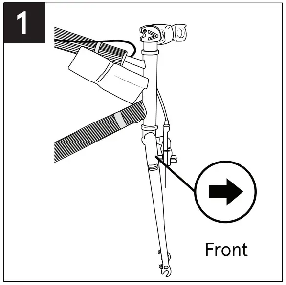
- Rotate the fork so that it is facing forward of the bike. (Fig. 1) Place the bike on the ground, so it’s standing upright on the fork dropouts and rear tire.
- Carefully cut all of the packing zip ties.
- Separate the front wheel from the bike by carefully slipping it away from the crank arm, which is resting within the spokes.
- Remove the accessory box and set it aside.
- Examine your new bike for any visible damage that may have occurred during shipping.NOTE: For tightening all fasteners, please refer to Appendix D in the back of your owner’s manual for all fastener torque specifications.

STEP 2: SADDLE
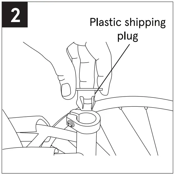
- Remove the plastic shipping plug from the top of the seat tube. (Fig. 2)
- Use the included Allen wrench to loosen the seat clamp at the top of the seat tube.
- RECOMMENDED: Apply a thin layer of grease to the end of the seat post.
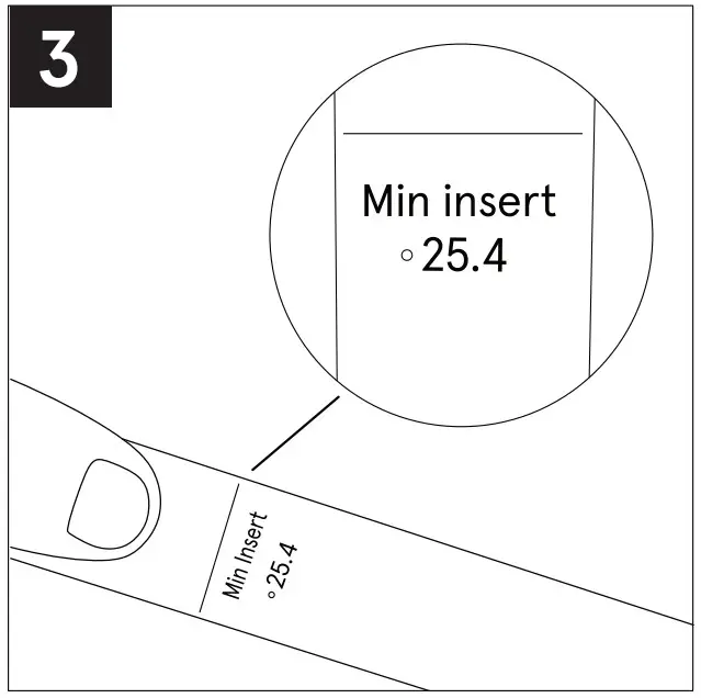
- Insert the seat with the seat post into the seat tube of the frame to at least the minimum insertion line on the shaft of the seat post.WARNING! The minimum insertion line must NOT show above the seat tube. (Fig. 3) 5 – Using the Allen wrench, tighten the seat clamp once it is at the correct height.NOTE: You can make the final adjustment to the height of the seat as needed after the bike is assembled.
 WARNING! Using the bike with the minimum insertion line on the lower portion of the seat post showing above the frame could result in a failure of the seat post and/or the frame causing a loss of control with potential injury to the rider. Such failures are not covered by warranty as it is improper to use of the product. (Fig. 3)
 |
 |
STEP 3: HANDLEBARS
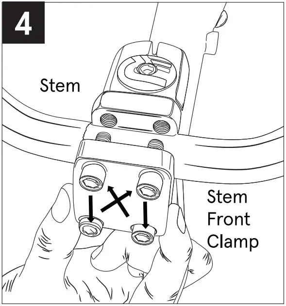
- Make sure that the handlebar stem and fork are facing towards the front of the bike. Remove the four faceplate bolts from the front of the handlebar stem.
- Remove the faceplate and place the handlebars in the stem, making sure the handlebars are centered.
- Replace the faceplate and insert each of the four bolts tightening each a little bit at a time to ensure even pressure on all four corners using a cross pattern (Fig. 4).NOTE: You’ll be able to adjust the angle of the handlebars by loosening the bolts and re-adjusting the bar.
STEP 4: FRONT WHEEL
Your bicycle is equipped with a quick-release wheel system (some models are front only).
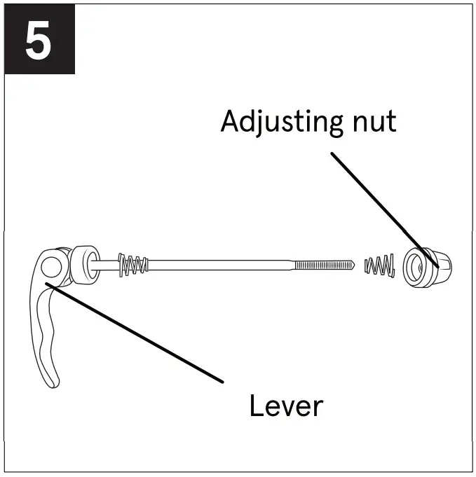
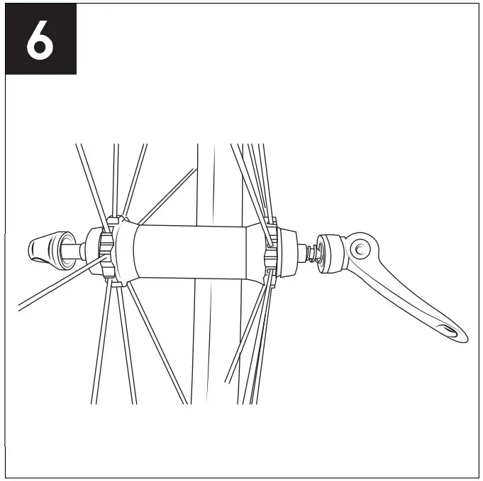
- Locate the quick release (OR) axle skewer in the small parts box. Unscrew and remove the adjusting nut from the skewer (Fig. 5). Remove one of the small cone-shaped springs and insert the skewer through the hollow axle of the front wheel. Re-install the cone-shaped spring (the small side towards the axle) and screw on the adjusting nut with just a few turns (Fig. 6).
- Insert the wheel into the fork with the skewer lever on the left side of the fork. If your front brake does not allow for the front tire to fit between the brake shoes, flip up the black release lever on the brake arm to allow the brake to spread apart.
- With the wheel quick-release lever open, tighten the skewer adjusting nut until it contacts the fork drop-out.
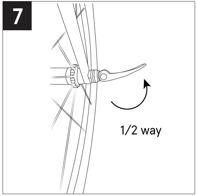
- Test for proper adjustment by closing the quick-release lever. When properly adjusted, the lever should begin to clamp the fork at about the halfway point of lever travel (Fig. 7). If the lever clamps the fork drop out before or after the halfway point of the lever travel, adjust by loosening or tightening the adjusting nut until the desired adjustment is reached.
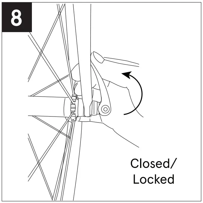
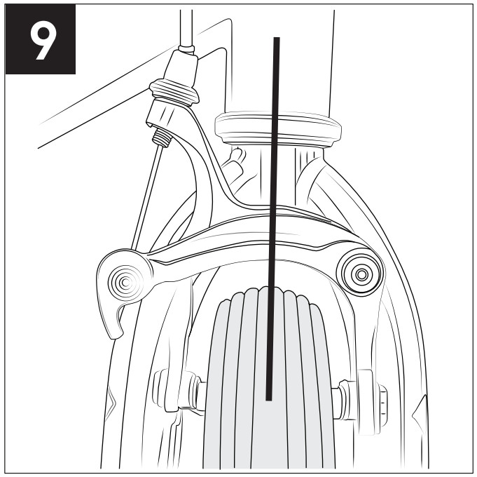
- Close the lever the rest of the way until it is pointing towards the back of the bike. There should be considerable resistance from the lever when closing it all the way (Fig. 8). If there is too much or too little resistance, adjust by loosening or tightening the adjusting nut until the desired resistance is reached. Be sure the wheel is centered in the fork before you tighten the quick-release skewer (Fig. 9).
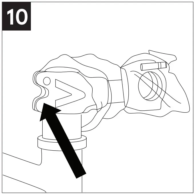
Align the handlebar stem to the front wheel, when aligned, tighten the two stem pinch bolts located at the rear of the stem by alternating between the two bolts tightening each a little at a time until both are secure, and hold the stems firmly in place – the stem should not move from side-to-side (Fig. 10).WARNING! Do not tighten the OR skewer as if it is a screw, a nut, or a wing-nut when attaching the wheel to the fork. Take your bike to a professional bikes shop and have them check the OR skewer adjustment before your first ride. An improperly adjusted OR skewer can cause the front wheel to fall out of the forks potentially causing serious injury to the rider.
 |
 |
 |
 |
 |
 |
STEP 5: PEDALS
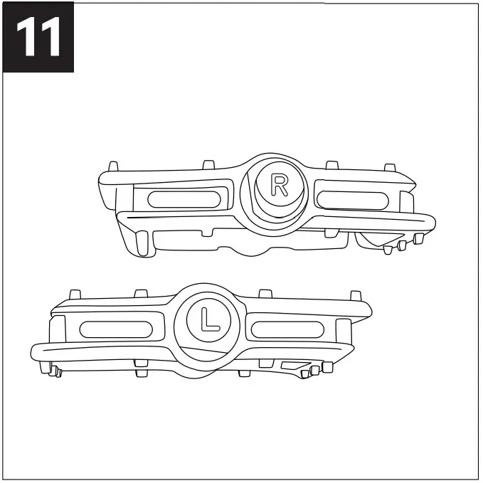
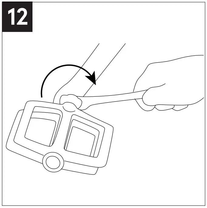
- Locate the pedal stamped “R” on the end of the spindle (this is the RIGHT pedal spindle) (Fig. 11).
- Carefully insert the right pedal into the right side crank arm (the side with the chain) and thread it clockwise (Fig. 12). You should be able to thread the pedal part of the way by hand with minor resistance. If it seems difficult and binds, stop, remove the pedal, realign the threads and try again. Be sure you are turning the right pedal axle in a clockwise direction! RECOMMENDED: Apply some grease to the pedal threads prior to installation.
- Tighten the pedal with a 15mm or adjustable wrench until the pedal is securely attached to the crank arm. Pedals need to be tightened with enough force so it does not come to lose.
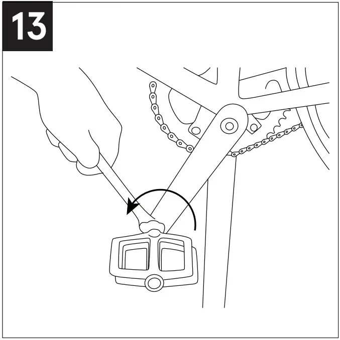
- Locate the pedal stamped “L” on the end of the spindle (this is the LEFT pedal). RECOMMENDED: Apply some grease to the left crank, insert your left pedal into the left side crank arm.
- Thread it counterclockwise and tighten with a 15mm or adjustable wrench following the instructions in step #3 above (Fig. 13).NOTE: Be sure to tighten both pedals with an adjustable wrench or 15mm open-end wrench to the recommended torque specification otherwise they will unscrew while riding causing an unsafe condition for the rider and damaging the threads in the crank.
STEP 6: BRAKES
NOTE:
- We highly recommend taking your bike to a local bike shop and having your brakes set up by a professional mechanic before your first ride.
- We strongly advise you to read “Brakes” under the TECH section of your Owner’s Manual.
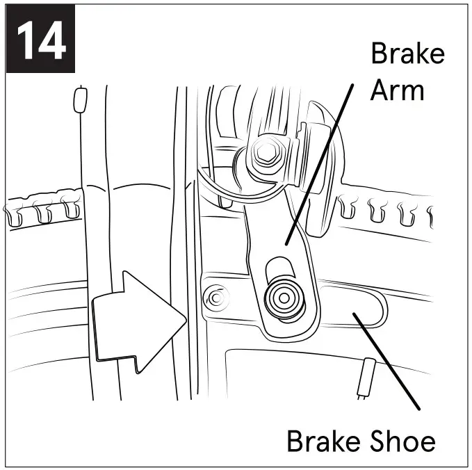
- Be sure that the brake pads are aligned with the curve of the rim and that they contact the rim surface flat and evenly (Fig. 14). The brake shoe angle and height can be adjusted by loosening the alien bolt attaching the brake shoe to the brake arm.
- Loosen the brake cable anchor at the brake arm held by an alien bolt allowing the brake cable to freely glide through its anchor.
- Squeeze the brake arms together until the brake shoes contact the rim surface. Be sure that the black release lever at the brake arm anchor is in the down position. Pull the cable taught through its anchor and tighten the cable anchor bolt (Fig. 15).
- Squeeze the brake lever several times to take the stretch out of the cable and make sure that it does not slip through its anchor. If the cable tension is too tight to allow the wheel to spin freely, loosen the anchor bolt and give the cable slack. If the cable has too much slack and you cannot apply enough stopping force to the rim, repeat procedure #3 to take the slack out of the cable.NOTE: Be sure to tighten both pedals with an adjustable wrench or 15mm open-end wrench to the recommended torque specification otherwise they will unscrew while riding causing an unsafe condition for the rider and damaging the threads in the crank.Be sure that the brake arms are evenly spaced from the wheel and there is some clearance between the brake pads and the rim surface. If the arms are not evenly spaced from the wheel, you can balance the spacing by gripping the brake assembly and rotating until it is centered with the wheel.

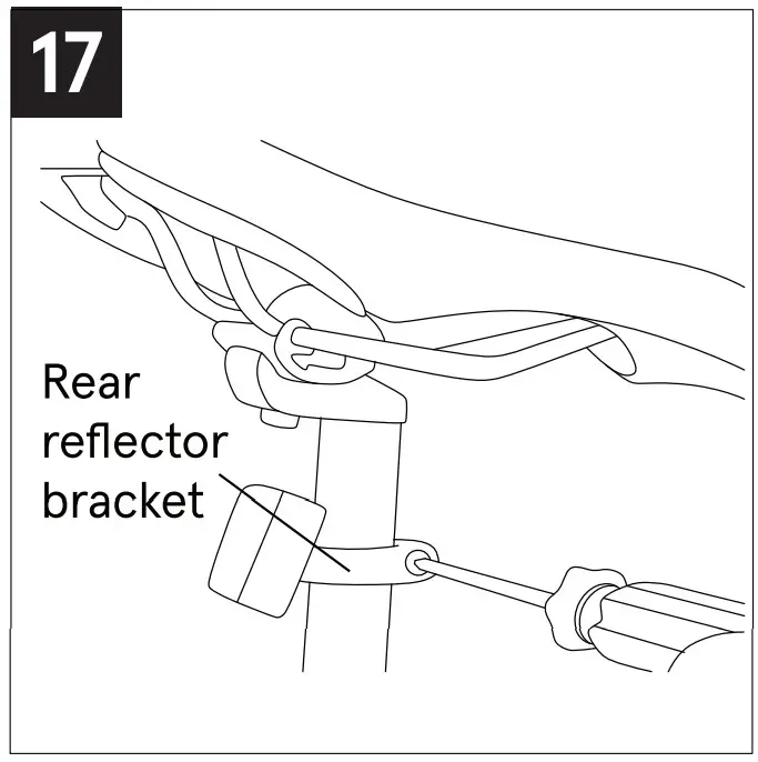
STEP 7: REFLECTORS
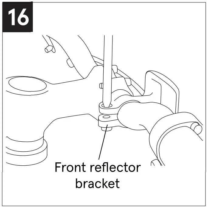
- Attach the plastic bracket to the handlebar and seat post (Fig. 16 & 17).
- Slide the white reflector onto the bracket. It should click as it locks in place.
- Attach the wheel reflectors onto the spokes of the wheels (these may already come installed by the factory).
 |
 |
STEP 8: GEARS
NOTE:
- We strongly advise you read “Shifting Gears” under the TECH section of your Owner’s Manual.
- You must be pedaling with light pedal pressure when shifting for the gears t o shift. For best results shift one gear at a time. Attempting to shift multiple gears at one time may cause the system to jam, fail, or the chain to fall off. Always downshift into an easier gear before coming to a complete stop.
The gears on this model come adjusted from the factory. If the gears need adjustment, please have this done by a professional bike shop.
STEP 9: TIRES
- Locate the tire manufacturer’s recommended inflation pressure found on the tire sidewall (listed as “PSI”).
- Using a hand or floor pump with a gauge, begin to inflate the tire to half its recommended inflation pressure and check to see that the tire is properly seated on the rim. Be sure to inspect both sides of the tire for proper fit.
- If the tire is seated unevenly or bulges out along the rim, let some air out of the tire and reposition the tire by hand so that it sits evenly on the rim.
- Continue to inflate the tire to the manufacturer’s recommended pressure.
- Do not exceed the recommended pressure as this will cause an unsafe condition potentially causing the tire to unexpectedly explode.
- Do not use a compressed air device to inflate your tires as the rapid inflation of the tire can cause it to explode.NOTE: Tires and tubes are not warranted against damage caused by over-inflation or punctures from road hazards.
BEFORE YOUR FIRST RIDE
We strongly recommend you take your bike to a professional bike shop and have them check your work and fine-tune the bike to ensure your bike is safe to ride.
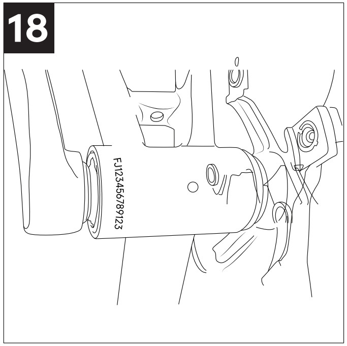
SERIAL NUMBER
It is important that you locate and record the serial number of your bicycle in case of a recall or if the bicycle is stolen. The serial number can be found under the crank bottom bracket stamped into the frame (Fig. 18).
[xyz-ips snippet=”download-snippet”]