Revision: CP-UBX-UDX-VENT (03-21) 1034631-0Supersedes: — (Original Version)
VENTING INSTRUCTIONS FOR UNIT HEATERSMODEL UBX: STANDARD POWER VENT BLOWER TYPEMODEL UDX: STANDARD POWER VENT FAN TYPE
GENERAL INFORMATION
This manual applies only to venting instructions and must be used with the installation manual. Both manuals are shipped with the heater. If either manual is missing, contact your distributor before beginning installation.
Important Safety Information
Please read all information in this manual thoroughly and become familiar with the capabilities and use of your appliance before attempting to operate or maintain this unit. Pay attention to all dangers, warnings, cautions, and notes highlighted in this manual. Safety markings should not be ignored and are used frequently throughout to designate a degree or level of seriousness.
DANGER: A danger statement describes a potentially hazardous situation that if not avoided, will result in severe personal injury or death and/or property damage. WARNING: A warning statement describes a potentially hazardous situation that if not avoided, can result in severe personal injury and/or property damage.CAUTION: A caution statement describes a potentially hazardous situation that if not avoided, can result in minor or moderate personal injury and/or property damage. NOTE: A note provides important information that should not be ignored.CAUTION
These units should not be used in an application where the heated space temperature is below 50°F (10°C). Operating under low ambient conditions may cause condensate to form in the heat exchanger.
DANGER
- Each heater requires its own individual vent pipe run and vent cap. Manifolding of vent runs can cause recirculation of combustion products into the building. Failure to comply could result in severe personal injury, death, and/or property damage.
- Heaters certified for residential use are intended for the heating of non-living spaces that are attached to or part of a structure that contains space for family living quarters. They are not intended to be the primary source of heat in residential applications or to be used in sleeping quarters.
- Installation should be performed by a qualified agency in accordance with these instructions. The qualified service agency installing this unit is responsible for the installation.
Venting Requirements
- These unit heaters are certified as Category III heaters and are designed to operate safely and efficiently with either a horizontal or vertical vent. Comply with the specific requirements and instructions.
- These unit heaters are certified for commercial/industrial installation. Model UDX heaters in unit size 030, 045, 060, 075, 100, and 125 are also certified for residential installation. Requirements and instructions vary depending on whether the installation is residential or commercial/industrial. Select and follow the venting instructions that apply to the installation only.
GENERAL INFORMATION–CONTINUED
Venting Requirements–Continued
- Venting must be in accordance with local codes and with the National Fuel Gas Code Z223.1 or CAN/CSA B149.1 and B149.2, Installation Code for Gas Burning Appliances and Equipment. Local requirements supersede national requirements.
CAUTION
- When an existing appliance is removed or replaced in a venting system, verify that the venting system is properly sized to vent the new appliance. An improperly sized venting system may result in the formation of condensate, leakage, and/or spillage.
- Do not intermix different vent system parts from different manufacturers in the same venting system.
- Do not vent into an existing gravity vent or chimney.
Venter (Flue) Outlet Diameter
- Depending on the size of the vent pipe, either attach the vent pipe directly to the collar or to a taper-type connector.
- For category, I vent pipe, attach a 4-inch appliance adapter (available from the category I pipe manufacturer) directly to the collar, and then use a reducer if using a 3-inch pipe.
- For category III vent pipe, attach a 4-inch appliance adapter (available from the category III pipe manufacturer) directly to the collar and then use a reducer if using a 3-inch pipe. · Refer to Table 1 for venter (flue) outlet diameters.
Vent System Sealing
Vent system joints depend on the type of pipe being used:
- Category III pipe: follow manufacturer’s instructions for joining pipe sections–connect venter outlet or the ventcap using secure, sealed joints that follow a procedure best-suited o the style of Category III pipe being used.
- Single-wall galvanized pipe (26-gauge or heavier): secure slip-fit connections using sheet metal screws orrivets–seal all joints and seams inside the building using aluminum tape or silicone sealant.
- Double-wall type B vent pipe: join pipe sections in accordance with the pipe manufacturer’s requirement–refer to the illustrated instructions in APPENDIX A to connect double-wall pipe to the heater collar, single-wall pipe, and vent cap.
| Table 1. Venter (Flue) Outlet Diameter | ||
|
Unit Size |
||
| 030–125 |
150–250 |
300, 350, 400 |
| Inches (mm) | ||
|
4 (102) |
5 (127 |
6 (152) |
Vent System Support Requirements
- Support horizontal runs every six feet (1.8 meters).
- Support vertical runs—of type B double-wall, category I, or category III vent pipe—in accordance with the pipe manufacturer’s requirements.
- Support vertical single-wall pipe in accordance with accepted industry practice.
⚠ CAUTION ⚠
- Do not rely on the heater to support either horizontal or vertical vent pipe.
- Use non-combustible supports on vent pipe.
Condensation Mitigation
- On units with long vent runs—over 50% of maximum vent length allowed—or installed in low ambient conditions (below 50°F), it is recommended that vent pipes be fitted at the low point of the vent system with a tee, a drip leg, and a cleanout cap to prevent any moisture in the vent pipe from entering the unit. The drip leg should be inspected and cleaned out periodically during the heating season.
- Any length of single-wall vent pipe exposed to cold air or run through an unheated area or an area with an ambient temperature of 50°F or less must be insulated along its entire length with a minimum of 1/2-inch foil-faced fiberglass, 1-1/2# density insulation.
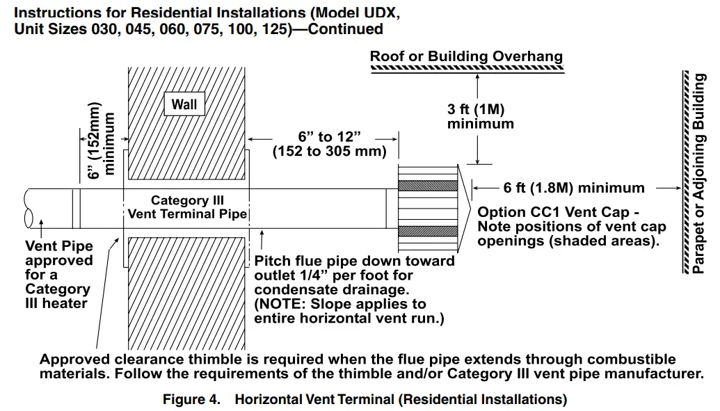
- On horizontal vent runs, the flue pipe must be pitched down toward the terminal end—1/4-inch per foot for condensate drainage—for the entire length of the horizontal vent run.
⚠ CAUTION ⚠
- Failure to pitch the vent run properly may damage the heater due to condensate running back into the unit.
- Exceeding vent pipe diameter and length requirements may result in condensate forming in the vent pipe.
Vent Terminal (Type of Pipe and Vent Cap) Requirements
⚠ DANGER ⚠
- To prevent combustion products from entering the occupied space, all vent terminations must be positioned or located away from fresh air intakes, doors, and windows. Failure to comply could result in severe personal injury or death and/or property damage.
- Consider local snow depth conditions. The vent must be at least 6 inches (152 mm) above the anticipated snow depth.
⚠ WARNING ⚠
- A different style vent cap could cause nuisance problems or unsafe conditions. The vent cap must be the same size as the vent pipe.
- Do not locate a vent termination where it may cause hazardous frost or ice accumulations on adjacent property surfaces.
- Maintain the required clearance from the wall to the vent terminal cap for stability under wind conditions and to protect the building.
- Refer to Table 2 for horizontal vent terminals.NOTE: Products of combustion can cause discoloration of some building finishes and deterioration of masonry materials. Applying a clear silicone sealant that is normally used to protect concrete driveways can protect masonry materials. If discoloration is an esthetic problem, relocate the vent or install a vertical vent.
| Table 2. Minimum Clearance Requirements for Horizontal Vent Terminal | |
| Component/Structure | Minimum Clearance. All Directions Unless Specified (Feet (Meters)) |
| Forced air inlet within 10 feet (3.1 meters)* | 3 (0.9) above |
| The combustion air inlet of another appliance | 6 (1.8) |
| Mechanical air supply inlet to any building | Canada: 6 (1.8) |
| Any building opening (door, window. or gravity air inlet) | 4 (1.2) h horizontal below |
| 1 (0.3) above ove | |
| Gas meter.** electric meter. and relief equipment | US: 4 (1.2) horizontal |
| Canada: 6 (1.8) horizontal | |
| Gas regulator** | US: 3 (0.9) horizontal |
| Canada: 6 (1.8) horizontal | |
| Adjoining building or parapet | 6 (1.8) |
| Adjacent public walkway | 7(2.1) above |
| Grade (ground level) | 3 (0.9) above |
| *Does not apply to the inlet of a direct-vent appliance. | |
| **Do not terminate the vent directly above a gas meter or service regulator. |
- Vertical vents must terminate a minimum horizontal and vertical distance from rooflines and adjacent walls or obstructions. These minimum distances are outlined as follows (based on National Fuel Gas Code requirements for vents with diameters less than 12”):
- For double-wall vent pipe and a horizontal distance to any vertical wall or similar obstruction of 8 feet or greater, the vent must terminate above the roof in accordance with Figure 1 and Table 3.
- For double wall vent pipe and a horizontal distance to any vertical wall or similar obstruction of fewer than 8 feet, the vent must terminate at least 2 feet above the highest point where it passes through a roof of a building and at least 2 feet higher than any portion of a building within a horizontal distance of 10 feet (refer to Table 3).
|
Table 3.Vent Termination Height |
|||||||||||
|
Roof Slope |
|||||||||||
| Flat to6/12 | Over6/12-7/12 | Over7/12-8/12 | Over8/12-9/12 | Over9/12-10/12 | Over10/12-11/12 | Over11/12-12/12 | Over12/12-14/12 | Over14/12-16/12 | Over16/12-18/12 | Over18/12-20/12 | Over20/12-21/12 |
|
Dimension H (Feet (Meters))* |
|||||||||||
| 1.0 (0.30) | 1.25 (0.38) | 1.5 (0.46) | 2.0 (0.61) | 2.5 (0.76) | 3.25 (0.99) | 4.0 (1.22) | 5.0 (1.52) | 6.0 (1.83) | 7.0 (2.13) | 7.5 (2.27) | 8.0 (2.44) |
| *See Figure 1. Termination locations for gas vents with listed caps 12″ (300 mm) or less in size at least 8″ (2.4 meters) from a vertical wall. |
INSTALLATION
Installation instructions vary depending on the installation type: commercial/industrial or residential. For commercial/ industrial installations, refer to the Instructions for Commercial/Industrial Installations (Model UBX or UDX, All Unit Sizes) section. For residential installations, refer to the Instructions for Residential Installations (Model UDX, Unit Sizes 030, 045, 060, 075, 100, 125) section. For vertically-vented category, I installations, refer to the Instructions for Commercial/Industrial or Residential Installations (Model UDX, Unit Sizes 030, 045, 060, 075, Vertical Category I) section.
Instructions for Commercial/Industrial Installations (Model UBX or UDX, All Unit Sizes)
A commercial/industrial installation may have either a horizontal or a vertical vent run. Install vent as follows:
- Select vent pipe:a. For either horizontal or vertical vent run, select vent pipe approved to UL standard 1738 for category III appliance or appropriately-sealed 26-gauge or heavier galvanized steel or equivalent single-wall pipe.b. If at least 75% of the equivalent length of the vent run is vertical, select double-wall type B vent pipe. If connecting double-wall pipe to the heater, follow instructions in APPENDIX A.
- Determine vent pipe diameter and length:a. Minimum vent length is 3 feet (1 meter).b. Use only one diameter of vent pipe for installation (refer to Table 4).
Table 4. Vent (Horizontal or Vertical) Pipe Diameters and Lengths UnitSize Vent PipeDiameter(Inches (mm)) Feet (Meters) Venter Outlet Connection** Maximum VentLength Equivalent Straight Length* 90-Degree Elbow 45-Degree Elbow 030 3 (76) 20 (6.1) 3 (0.9) 1.5 (0.5) 4- to 3-inch (102- to 76-mm) reducer*** 4 (102) 10 (3) 2 (0.6) 1 (0.3) 045 3 (76) 20 (6.1) 3 (0.9) 1.5 (0.5) 4- to 3-inch (102- to 76-mm) reducer*** 4 (102) 10 (3) 2 (0.6) 1 (0.3) 060 3 (76) 30 (9.1) 4 (1.2) 2 (0.6) 4- to 3-inch (102- to 76-mm) reducer*** 4 (102) 15 (4.6) 2 (0.6) 1 (0.3) 075 4 (102) 30 (9.1) 4 (1.2) 2 (0.6) 100 4 (102) 40 (12.2) 5 (1.5) 2.5 (0.8) 125 4 (102) 40 (12.2) 5 (1.5) 2.5 (0.8) 150 5 (127) 35 (10.7) 5 (1.5) 2.5 (0.8) 175 5 (127) 35 (10.7) 5 (1.5) 2.5 (0.8) 200 5 (127) 50 (15.2) 5 (1.5) 2.5 (0.8) 225 5 (127) 50 (15.2) 5 (1.5) 2.5 (0.8) 250 5 (127) 50 (15.2) 5 (1.5) 2.5 (0.8) 300 6 (152) 50 (15.2) 5 (1.5) 2.5 (0.8) 350 6 (152) 50 (15.2) 7 (2.1) 3.5 (1.1) 7 (178) 50 (15.2) 4.5 (1.4) 2.25 (0.7) 6- to 7-inch (152- to 178-mm) enlarger 400 6 (152) 50 (15.2) 8 (2.4) 4 (1.2) 7 (178) 50 (15.2) 5 (1.5) 2.5 (0.8) 6- to 7-inch (152- to 178-mm) enlarger *Add all straight sections and equivalent lengths for elbows-the total combined length must not exceed the maximum vent length. **Field-supplied taper-type connection required at the center outlet. ***Refer to APPENDIX B. Determine venter (flue) outlet diameter (refer to Venter (Flue) Outlet Diameter section).
- Make all vent pipe joint connections in accordance with the Vent System Sealing section.
- Support all vent pipe runs in accordance with the Vent System Support Requirements section.
- Take appropriate steps to mitigate condensation in accordance with the Condensation Mitigation section.NOTE: Ensure that the terminal vent pipe is a double-wall type B pipe.
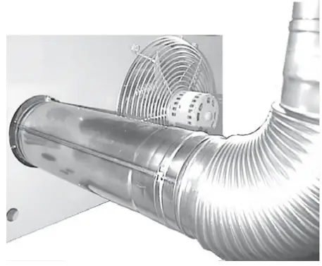
- Terminate vent as follows:a. Install double-wall type B terminal vent pipe (connect in accordance with APPENDIX A) and terminate vent with option CC1 or CC21 vent cap or Novavent #2NVTB4 vent cap.b. Refer to instructions shown in Figure 2 to install horizontal vent terminal.
c. Refer to instructions shown in Figure 3 to install vertical vent terminal.d. Ensure that vent terminal is installed in accordance with Vent Terminal (Type of Pipe and Vent Cap) Requirements section.


Instructions for Residential Installations (Model UDX, Unit Sizes 030, 045, 060, 075, 100, 125)
A Category III vent as defined by the National Fuel Gas Code Z223.1 or CAN/CSA B149.1 and B149.2 is required for a residential installation of model UDX units. Some venting requirements will vary, however, depending on whether the vent is horizontal or vertical. Install vent as follows:
- Select vent pipe approved to UL standard 1738 for category III appliance for either horizontal or vertical vent run.
- Determine vent pipe diameter and length:a. Minimum vent length is 3 feet (1 meter).b. Use only one diameter of vent pipe for installation (refer to Table 4).
- Determine venter (flue) outlet diameter (refer to Venter (Flue) Outlet Diameter section).
- Make all vent pipe joint connections in accordance with the Vent System Sealing section.
- Support all vent pipe runs in accordance with the Vent System Support Requirements section.
- Take appropriate steps to mitigate condensation in accordance with the Condensation Mitigation section.
- Terminate vent as follows:a. Install UL standard 1738 approved category III vent pipe and terminate vent with option CC1 or CC21 vent cap or Novavent #2NVTB4 vent cap.b. Refer to instructions shown in Figure 4 and to Table 2 to install horizontal vent terminal.c. Refer to instructions shown in Figure 5 to install vertical vent terminal.d. Ensure that vent terminal is installed in accordance with Vent Terminal (Type of Pipe and Vent Cap) Requirements section.
Instructions for Commercial/Industrial or Residential Installations (Model UDX, Unit Sizes 030, 045, 060, 075, Vertical Category I)
On vent systems where at least 75% of the equivalent length of the vent run is vertical and the vent terminates at least 5 feet above the vent outlet of the heater. All vertically vented heaters that are category I must be connected to a chimney or vent complying with a recognized standard or a lined masonry (or concrete) chimney with materialacceptable to the authority having jurisdiction. Venting into an unlined masonry chimney is not permitted. Install vent as follows:
- Select type of pipe for standard vertical (category I) vent. A double-wall vent pipe is recommended. Use single-wallvent pipe if requirements of the National Fuel Gas Code are followed. All pipes must be UL listed for category Iappliances.
- Determine vent pipe diameter and length for the vertical vent. Use only one diameter of vent pipe for installation(refer to Table 4).
- Determine venter (flue) outlet diameter (refer to Venter (Flue) Outlet Diameter section).
- Make all vent pipe joint connections in accordance with the Vent System Sealing section.
- Support all vent pipe runs in accordance with the Vent System Support Requirements section.
- Take appropriate steps to mitigate condensation in accordance with the Condensation Mitigation section.
- Terminate vent as follows:a. Install UL-listed category I terminal vent pipe and terminate vent with option CC1 or CC21 vent cap or Novavent#2NVTB4 vent cap.b. Refer to instructions shown in Figure 4 to install vertical vent terminal.c. Ensure that vent terminal is installed in accordance with Vent Terminal (Type of Pipe and Vent Cap) Requirements section.
APPENDIX A: INSTRUCTIONS FOR ATTACHING DOUBLE-WALL TYPE B VENT PIPE TO SINGLE-WALL PIPE
NOTE: Work quickly to assemble components before sealant dries.
STEP 1: Place a continual 1/4inch bead of silicone sealant around the circumference of the single-wall pipe. |
STEP 2: Before sealant can dry,insert the single-wall pipe into the inner pipe of the double-wall pipe until the bead of sealant contacts the inner pipe to create a sealed joint. |
STEP 3: Drill three small holes spaced equally around the double wall pipe below the sealant ring.Secure joint using 3/4-inch long sheet metal screws. Do not overtighten screws. |
|
STEP 4: Place continual 3/8inch bead of silicone sealant around the circumference of vent cap collar to preventany the water inside vent cap from running down the double-wall pipe. |
STEP 5: Before sealant can dry, insert collar on vent cap as far as possible inside the inner wall of the double-wall pipe. Apply silicone sealant to fully close any gaps between vent cap and double wall pipe to prevent waterfrom entering the double-wall pipe. |
STEP 6: Drill a small hole through the vent cap and double wall pipe. Secure joint using 3/4-inch-long sheet metal screw.Do not overtighten the screw. |
|
STEP 7: Place continual 1/4inch bead of silicone sealant around the circumference of venter outlet collar. |
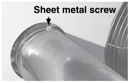
STEP 8: Before sealant can dry, slide double-wall pipe over collar so that collar is inside the inner pipe. Push double-wall pipe tight to the heater cabinet. Drill three small holes through the pipe and into collar spaced equally around pipe below sealant ring. Secure joint using 3/4-inch-long sheet metal screws. Do not overtighten screws. |
APPENDIX B: INSTRUCTIONS FOR INSTALLING FLEX-L BRAND CATEGORY III VENT PIPE
NOTES:
- SUPPLIER NOTE: The adapters for Flex-L vent pipe, which are not available from the heater manufacturer, are available from a Flex-L brand vent pipe distributor.
- These instructions are designed to assist the contractor who has selected to use Flex-L brand category III vent pipe to install a power-vented heater with a 4-inch (102-mm) venter outlet.
- Work quickly to assemble components before sealant dries.
|
|
 |
|
 |
|
- Attach adapter pipe or reducer to venter collar:a. Place continual bead (see Figure B1, DETAIL A) of high-temperature silicone around inside of pipe on the end of adapter or reducer that attaches to venter collar (end of the adapter with double emboss without locking ring hole).b. Push adapter pipe or reducer over flue collar.c. Drill 1/8-inch hole on top of overlap and secure joint using sheet metal screw (see Figure B1, DETAIL B).
DETAIL A
DETAIL B
DETAIL C
Figure B1. Reducer and Vent Cap
- Run vent pipe:a. Determine vent length in accordance with residential or commercial/industrial vent length requirements inInstallation section.b. If using a 4- to 3-inch (102- to 76-mm) reducer, follow vent pipe manufacturer’s instructions to attach a straight piece of 3-inch diameter horizontal pipe or elbow in any direction above horizontal. If using a 4-inch (102-mm) diameter 12-inch (305-mm) long adapter pipe, follow the vent pipe manufacturer’s instructions to attach the elbow in any direction above the horizontal or straight horizontal pipe.c. Follow pipe manufacturer’s instructions to connect vent pipe sections and install vent pipe run—length of the vent must not exceed the maximum allowed for the heater being installed.d. Extend vent pipe through wall or roof to outdoors. Approved clearance thimble is required when flue pipe extends through combustible materials. Follow requirements of pipe and thimble manufacturer. Be sure to comply with local and national codes when selecting vent terminal location. The vent pipe installer is responsible for following the manufacturer’s instructions and complying with all applicable codes.
- Attach vent cap ( see Figure B1, DETAIL C):a. Use option CC1 or CC21 vent cap or Novavent #2NVTB4 vent cap.b. Slide vent cap collar into the vent pipe.c. Drill three evenly-spaced 1/8-inch holes around the end of vent pipe through pipe and vent cap and secure joint using sheet metal screws.
 report this ad
Specifications and illustrations are subject to change without notice or incurring obligations.©2021 Nortek Global HVAC LLC, O’Fallon, MO.All rights reserved.CP-UBX-UDX-VENT (03-21) 1034631-0
[xyz-ips snippet=”download-snippet”]