RIDGID Kollmann Standard and Mini SeeSnake
Diagnostic Equipment User Manual


General Safety Information
![]() WARNING!
WARNING!
Read and understand all instructions. Failure to follow all instructions listed below may result in electric shock, fire, and/or serious personal injury.
SAVE THESE INSTRUCTIONS!
Work Area Safety
- Keep your work area clean and well lit. Cluttered benches and dark areas may cause accidents.
- Do not operate power tools in explosive atmospheres, such as in the presence of flammable liquids, gases, or dust. Power tools create sparks which may ignite the dust or fumes.
- Keep bystanders, children, and visitors away while operating tool. Distractions can cause you to lose control.
- Do not let visitors contact the tool or extension cord. Such preventative measures reduce the risk of injury.
Electrical Safety
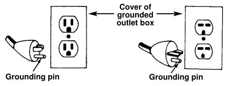
- Grounded tools must be plugged into an outlet, properly installed and grounded in accordance with all codes and ordinances. Never remove the grounding prong or modify the plug in any way. Do not use any adapter plugs. Check with a qualified electrician if you are in doubt as to whether the outlet is properly grounded. If the tool should electrically malfunction or break down, grounding provides a low resistance path to carry electricity away from the user.

- Avoid body contact with grounded surfaces such as pipes, radiators, ranges and refrigerators. There is an increased risk of electrical shock if your body is grounded.
- Do not expose electrical tools to rain or wet conditions. Water entering a tool will increase the risk of electrical shock.
- Do not abuse cord. Never use the cord to carry the tool or pull the plug from an outlet. Keep cord away from heat, oil, sharp edges, or moving parts. Replace damaged cords immediately. Damaged cords increase the risk of electrical shock.
- When operating a power tool outside, use an outdoor extension cord marked “W-A” or “W ” . These cords are rated for outdoor use and reduce the risk of electrical shock.
- Connect the tool to an AC power supply that matches the name plate specification. Incorrect voltage supply can cause electrical shock or burns.
- Use only three-wire extension cords which have three-prong grounding plugs, and three-pole receptacles which accept the tools plug. Use of other extension cords will not ground the tool properly and increase the risk of electrical shock.
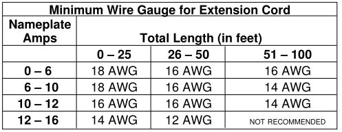
- Use proper extension cords. (See chart.) Insufficient conductor size will cause excessive voltage drop and loss of power.
- Keep all electrical connections dry and off the ground. Do not touch plugs or tool with wet hands. This reduces the risk of electrical shock.
Battery Precautions
- Use only the size and type of battery specified.
- Be sure to install the battery with the correct polarity as indicated in the battery compartment.
- Recharge batteries with charging units specified by the battery manufacturer. Using an improper charger can overheat and rupture the battery.
- Properly dispose of the battery. Exposure to high temperatures can cause the battery to explode, so do not dispose of in a fire. Some countries have regulations concerning battery disposal. Please follow all applicable regulations.
Personal Safety
- Stay alert, watch what you are doing and use common sense when operating a power tool. Do not use tool while tired or under the influence of drugs, alcohol, or medications. A moment of inattention while operating power tools may result in serious personal injury.
- Dress properly. Do not wear loose clothing or jewelry. Contain long hair. Keep your hair, clothing, and gloves away from moving parts. Loose clothes, jewelry, or long hair can be caught in moving parts.
- Avoid accidental starting. Be sure switch is OFF before plugging in. Carrying tools with your finger on the switch or plugging in tools that have the switch on invites accidents.
- Do not overreach. Keep proper footing and balance at all times. Proper footing and balance enables better control of the tool in unexpected situations.
- Use safety equipment. Always wear eye protection. Dust mask, non-skid safety shoes, hard hat, or hearing protection must be used for appropriate conditions.
- Gloves should always be worn for health and safety reasons. Sewer lines are unsanitary and may contain harmful bacteria.
- Heed warnings. All warnings on the product and in the Operator’s Manual should be adhered to.
- Use proper accessories. Do not place this product on any unstable cart or surface. The product may fall causing personal injury and/or damage to the product.
- Prevent object and liquid entry. Never spill liquid of any kind on the product. Never push objects of any kind into this product through openings as they may touch dangerous voltage points or short to parts that could result in a fire or electrical shock.
NOTE! Check to make sure pipe not electrically hot. In some cases ground circuits may be returned to cast iron pipes causing them to be electrically charged. As sections of pipe joined with shielded hub-less connections or compression gaskets may be electrically isolated, care should be taken to check the entire length on any pipe you are going to inspect.
Tool Use and Care
- Do not use tool if switch does not turn it ON or OFF. Any tool that cannot be controlled with the switch is dangerous and must be repaired.
- Store idle tools out of the reach of children and other untrained persons. Tools are dangerous in the hands of untrained users.
- Maintain tools with care. Properly maintained tools are less likely to cause injury.
- Check for misalignment or binding of moving parts, breakage of parts and any other condition that may affect the tool’s operation. If damaged, have the tool serviced before using. Many accidents are caused by poorly maintained tools.
- Use only accessories that are recommended by the manufacturer for your tool. Accessories that may be suitable for one tool may become hazardous when used on another tool.
- Inspect tool and extension cords periodically and replace if damaged. Damaged cords increase the risk of electrical shock.
- Keep handles dry and clean; free from oil and grease. Allows for better control of the tool.
- Store tools in dry place. Such measures reduce the risk of electrical shock.
- Protect against lightning. For added protection for this product during a lightning storm, or when it is left unattended and unused for long periods of time, unplug it from the wall outlet. This will prevent damage to the product due to lightning and power surges.
- Protect against excessive heat. The product should be situated away from heat sources such as radiators, heat registers, stoves or other products (including amplifiers) that produce heat.
- Provide adequate ventilation. Slots and openings in the cabinet are provided for ventilation and to ensure reliable operations of the product. These openings must not be blocked or covered. This product should not be placed in a built-in installation such as a rack or bookcase unless proper ventilation is provided or the manufacturer’s instructions have been adhered to.
Service
- Tool service must be performed only by qualified repair personnel. Service or maintenance performed by unqualified repair personnel could result in injury.
- When servicing a tool, use only identical replacement parts. Follow instructions in the Maintenance Section of this manual. Use of unauthorized parts or failure to follow maintenance instructions may create a risk of electrical shock or injury.
- Follow instructions for lubricating and changing accessories. Accidents are caused by poorly maintained tools.
- Provide proper cleaning. Unplug this product from the wall outlet before cleaning. Do not use liquid cleaners or aerosol cleaners. Use a damp cloth for cleaning.
- Conduct a safety check. Upon completion of any service or repair of this product, ask the service technician to perform safety checks to determine that the product is in proper operating condition.
- Damage to the product that requires service.Unplug this product from the wall outlet and refer servicing to qualified service personnel under any of the following conditions:
- When the power cord or plug is damaged;
- If liquid has been spilled, or object have fallen into product.;
- If product has been exposed to rain or water;
- If product does not operate normally by following the operating instructions;
- If the product has been dropped or damaged in any way.
- When the product exhibits a distinct change in performance.
If you have any questions regarding the service or repair of this machine, call or write to:
Ridge Tool CompanyTechnical Service Department400 Clark StreetElyria, Ohio 44035-6001Tel: (800) 519-3456E-mail: [email protected]On the Web: www.ridgid.comor www.seesnake.com
In any correspondence, please give all the information shown on the nameplate of your tool including model number, voltage and serial number.
Specific Safety Information
![]()
WARNING
Read this operator’s manual carefully before using this Diagnostic Equipment. Failure to understand and follow the contents of this manual may result in electrical shock, fire and/or serious personal injury.
Call the Ridge Tool Company, Technical Service Department at (800) 519-3456 if you have any questions.
Tool Safety
- Before using, test the Ground Fault Circuit Interrupter (GFCI) provided with the power cord to ensure it is operating correctly. GFCI reduces the risk of electrical shock.
- Extension cords are not recommended unless they are plugged into a Ground Fault Circuit Interrupter (GFCI) found in circuit boxes or receptacles. The GFCI on the camera control unit power cords will not prevent electrical shock from the extension cords.
- Do not operate the system with electrical components removed. Exposure to internal parts increases the risk of injury.
- Do not place the camera control unit in water or on a wet surface. Water entering the housings will increase the risk of electrical shock.
- Do not use as a chair or table. Do not drop or shock. Can result in damage to the unit which increases the risk of electrical shock.
- Product and cart should be moved with care. Quick stops, excessive force and uneven surfaces may cause the product and cart combination to overturn.
![]()
CAUTIONCamera head can get HOT! Turn OFF camera while not in use.
SAVE THESE INSTRUCTIONS!
Description, Specifications and Standard Equipment
Description
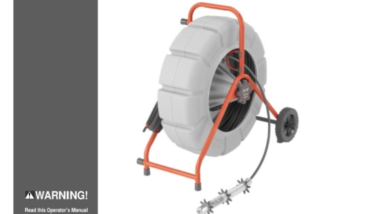
The RIDGID/Kollmann SeeSnake pipe inspection system is a powerful set of tools that helps you locate and diagnose problems in drain and sewer systems. The SeeSnake family of diagnostic equipment includes Standard and Mini camera reels, a choice of camera control, video display and recording options, and a locating system to help you quickly pinpoint problems under ground. Every component in the SeeSnake system has been engineered and tested to ensure rugged and reliable operation on the kinds of jobs you encounter every day.
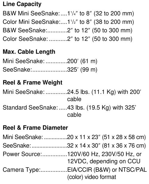
SeeSnake pipe inspection cameras are ideal for inspecting 2″ to 12″ (Standard SeeSnake) and 1 1 / 4 ″ to 8″ (Mini SeeSnake) drain lines. Their flexible camera heads can negotiate multiple hard 90° bends. The fiberglass-reinforced push cable is flexible enough to easily travel through bends, yet stiff enough to push the camera head up to 325′ (Standard SeeSnake) and 200′ (Mini SeeSnake).
System ComponentsThe SeeSnake pipe inspection system contains the following four sub assemblies: Camera Head, Reel/Frame, Camera Control Unit and a Locating System. Please take a moment to learn the following details and the functions of each of these components. (Figures 1 – 9)
- Camera HeadThe camera head has adjustable lighting elements and a highly scratch-resistant sapphire window (Lens Port). This coupled with the stainless steel armoring allows the camera to withstand repeated battering in cast iron pipes. The Camera is rated to a water depth of 330′.
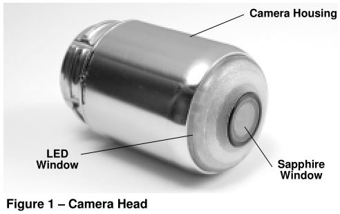
LED – Light Emitting Diode. Solid-state light that, unlike an incandescent lamp does not have a fragile filament.
LED Window – The donut shaped window that covers and protects the LEDs from abrasion.
Spring Assembly – Flexible stainless steel spring and associated components that hold the camera to the push cable. It provides a flexible transition from camera to push cable, and protects the terminations within the spring. (Figure 2)
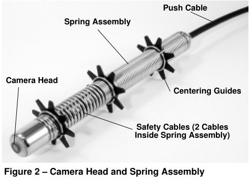
Safety Cables – Stainless steel cables (two) within the spring assembly. They connect between the push cable termination and the locking sleeve, attaching to the connector at the back of the camera head. These prevent the spring from overextending when pulling the camera out of a pipe, and ensure the connection to the camera is never stressed.
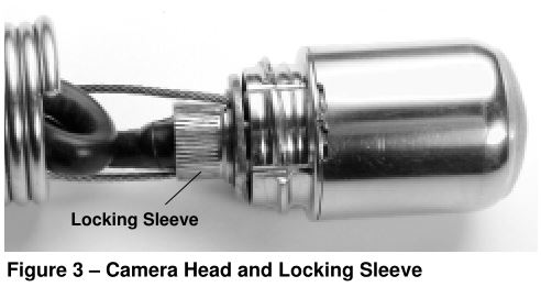
Locking Sleeves – This device is found at the rear of the camera within the spring (Figure 3), and with the connectors on the cable hub (dry end), and both ends of the system cable (Figure 5). The camera locking sleeve holds the connector in place and serves as an anchor for the safety cables. This device is unscrewed from the back of the camera to detach the connector from it.
The other locking sleeves help ensure a solid connection at the cable “dry end,” hub, or CCU. The locking sleeves are turned or twisted, but the connectors are never twisted – just pulled straight apart.
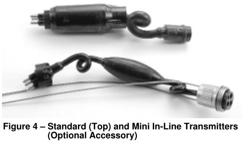
In-Line Transmitter – If you’re planning to pinpoint the problem in a line, you will want a SeeSnake ® In-Line Transmitter, which is sold as an option.
Spanner Wrench – One piece wrench used to engage the end of the spring and hold it while removing the camera head. (See “Removing Camera Head” in the Corrective Maintenance section.)
Centering guides – Installed over the spring, guides can help you see the top of larger diameter pipes more clearly and raise the camera head out of water or sediment that may obscure the lens. (See Page 15.)
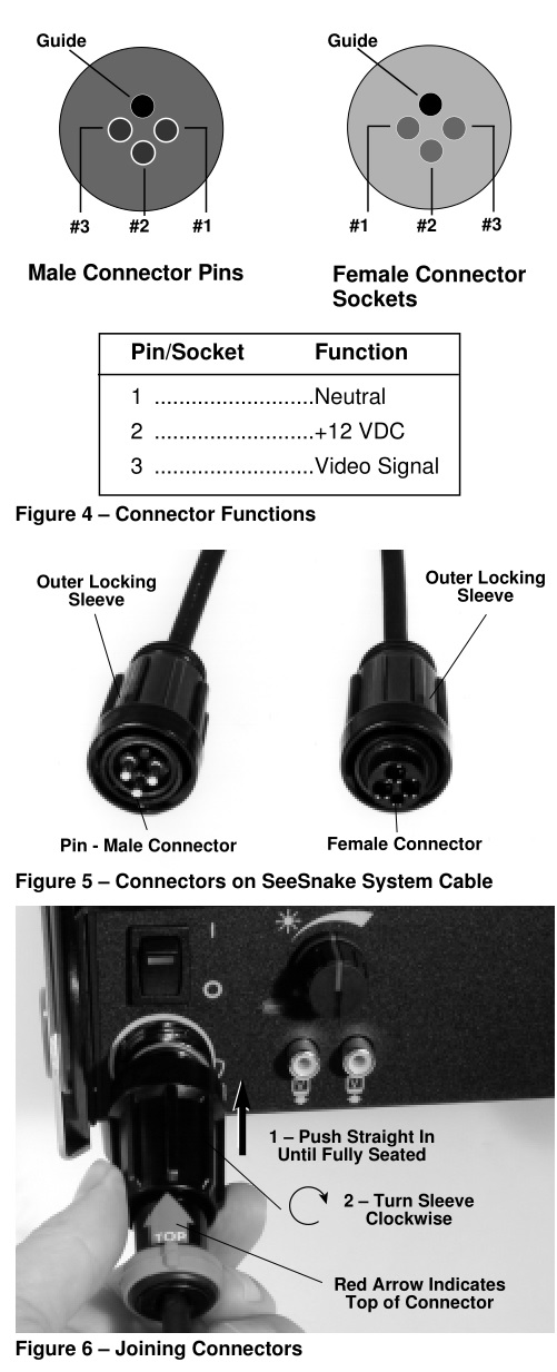
Connectors – All the “plugs” in the system that connect the camera, push cable, hub, System Cable and Camera Control Unit. These are the connectors that have guide pins (male) and guide sockets (female) and an outer locking sleeve to ensure the connectors are securely mounted. These connectors ARE NOT to be confused with 120 volt (or 230V) AC outlet plugs, or any video/audio jacks. Every SeeSnake System connector in the system is waterproof and uses a standardized pin pattern, which allows you to plug components into one another for easy troubleshooting. Refer to Figures 1 through 3.
![]()
WARNINGBending or twisting the connectors will lead to premature failure. Do Not bend or twist connectors! Twist only the locking sleeve!
2) Reel/Frame
Push Cable – terminates right behind the spring. It has a high-strength fiberglass core that’s stiff enough to push long distances and flexible enough to negotiate tight turns. The tough outer jacket resists abrasion and Kevlar braid provides added strength.
Reel – The push cable is stored in the molded gray drum, which is rust and dent-proof and keeps waste water off your customers’ carpets. Mercury-free slip rings inside the drum’s hub provide a rotating electrical connection between the drum and frame and allow operation at any angle (i.e. rooftops).
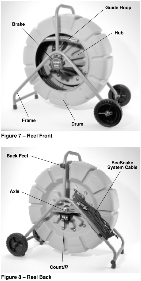
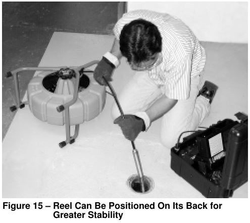
Frame – A sturdy, powder coated metal structure that the reel is mounted to. The frame has a second set of feet on the back side of the reel, allowing the system to rest on its back (open-end-up) for greater stability.
The guide hoop on the frame helps the push cable feed in and out of the drum properly, and the brake knob lets you adjust the amount of drag on the cable for maximum control. (Figure 7)
The CountIR measures the distance the cable has traveled inside the pipe and can also display the day, date, time, and up to 33 pages of user defined text information.
The SeeSnake System Cable stores on the frame and provides the connection between the reel and the camera control unit. (Figure 8)
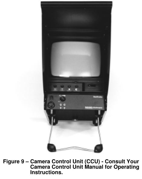
3) Camera Control Unit (CCU)This unit provides power to the camera reel and system accessories. It also provides a control that adjusts the camera’s lighting and activates the In-Line transmitter. These range from a unit without a built-in monitor (Power Pack) to sophisticated units with color monitors and audio and video recording capability. Units may be powered by any 120 volt AC source (or 230 volts in some countries – this requires a different camera control unit than the 120 volt) or 12VDC, and some include recharge- able batteries. (Figure 9)
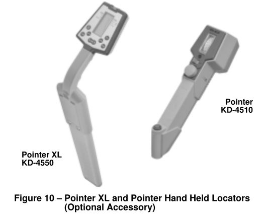
4) Locating System (optional)This consists of a miniaturized transmitter and a hand-held receiving unit. The transmitters operate at the industry-standard of 512Hz, are extremely durable, require no batteries for operation and do not interfere with camera’s ability to go through turns. Optional receiving units are available with either an analog readout or a digital display with push-button depth calculation.
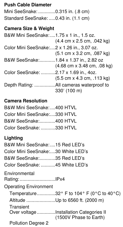
Specifications
Standard Equipment
- Camera Reel with Push Cable
- Camera Head
- Cable CountIR
- Centering Guides (standard and ball-type)
- C-Rings (for holding Centering Guides onto spring assembly)
- SeeSnake System Cable
- Universal Spanner Wrench (for Camera Head removal)
- Pair of Plastic Coated Gloves
- SeeSnake Instructional Video
- Operator’s Manual
Set Up and Operation
Equipment Setup
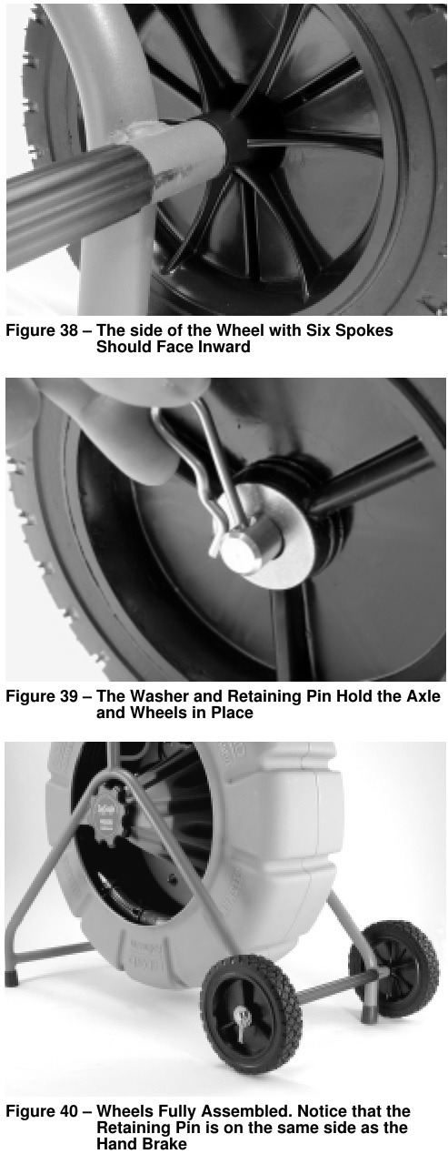
- For Standard SeeSnake reels, install the wheels as described in appendix A.
- Place the reel so the push cable is easy to manage as you push the camera through the line. Three to five feet from the access point seems to work best.
- Set up the Camera Control Unit (CCU) so its monitor screen is easy to see and it’s controls are easy to reach during use. In brightly lit areas, point the monitor screen away from bright light sources and/or use the monitor’s sun shade to reduce glare.
- Adjust the reel’s brake so the drum turns easily when you pull cable from the reel, but stops turning when you stop pulling the cable; if the drum turns too easily, excess cable could wind out of the reel.
Connections
- Plug the Camera Control Unit into an AC outlet and reset the GFCI if necessary.
- Unwrap the SeeSnake System Cable from its holder on the reel frame and plug its connector into the matching connector on the CCU. To join the connectors, align the guide pin to the guide socket, push the connector straight in and tighten the outer locking sleeve. (Figure 6)
NOTE! Twist only the locking sleeve! Never bend or twist the connector! Bending or twisting the connector will lead to premature failure. When unplugging you may wiggle a little, if necessary, but do not bend or twist.
Operation
- Place the camera head into the reel’s guide hoop as shown in Figure 4, and turn the CCU’s power ON. You should see the words “SeeSnake CountIR” and a version number on the monitor screen. Leave the camera head in the guide hoop until this start-up screen disappears (approx. 15 sec.). If you do not see an image on the monitor, check to make sure its power is turned on.
- Put the camera head into the access point and adjust the camera’s lighting with the Dimmer/Transmitter control.
- Turn the CountIR’s display modes ON or OFF as desired. If you want to measure distance, reset its distance display to zero as described in the CountIR section.
- Adjust the monitor’s picture controls as necessary.
- To record the inspection, refer to the operator’s guide for the CCU you are using.
- If you are using a Mini SeeSnake with the optional In-Line Transmitter installed, you can activate it by rotating the Dimmer/Transmitter control knob counter-clockwise fully until it clicks into position.
NOTE! There is no need to activate the Standard SeeSnake In-Line Transmitter; it is always transmitting when the system is powered ON.
Pre-Checks
These Pre-Checks are needed before using the system for the first time. The operator should be aware of these and make periodic checks throughout the life of the unit.
Mechanical Checks
- Rotate the reel brake to a position that allows you to easily pull cable from the reel, yet stops immediately when you are not retrieving cable. For transport, add more friction to the brake. (Tighten)
- Grasp the spring assembly in one hand, and the camera head in the other. Ensure the spring is tightened ONLY to the point where the cut end of it is as far as it can go in the camera head’s threads. If it is under tightened, you should be able to physically screw the spring a little farther onto the camera’s threads. Be careful not to over tighten. If it is over tightened, the cut end of the spring will “crawl” up and over the threads. If this occurs, follow the procedures in the “Maintenance – Removing the Camera Head” section to properly seat the spring using the spanner wrench provided.
- Check to see that the connector at the end of the push cable is fully seated into the connector attached to the cone-shaped portion of the hub (inside the reel). Likewise, check that the system cable is completely plugged into the hub. Periodically inspect these connectors for good connections as the system is used. Be sure the locking sleeves on the connectors are tightened.
Electrical ChecksThe system should always produce a crisp picture that is free of noise and lines. Sometimes, especially during cold-weather conditions, it can take a moment for the system to heat up before it will produce the optimum picture. Otherwise, check that connectors are fully engaged and follow these guidelines:
- With the system energized, look to see that an even amount of light is coming from the LEDs. Place the camera in the reel, and give it a good spin while watching your monitor to test the slip ring. If you do not get a stable picture, call RIDGE Tool Technical Service at 800-519-3456.
- If your CCU has a VCR, refer to its owner’s manual for operating instructions.
SeeSnake Cable CountIRThe CountIR is located under the axle on the closed side of the drum and measures distance by counting drum rotations as you push the camera through the line. The CountIR superimposes the distance reading, date/time and user-defined text messages over the video. Please read the CountIR owner’s guide for complete operating and battery replacement instructions.
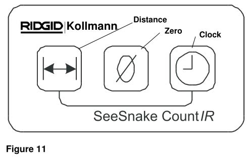
Keypad Button Description(Figure 11)
Distance ButtonPush to turn the distance display ON and OFF.
Clock ButtonPush to cycle through the Date/Time display options:• Date with Time• Date Only• Time Only• Date/Time OFF
Zero ButtonPush to reset the distance display to zero. This allows you to measure:• The distance from the access point to the camera’s current position• The distance between any two points in the line.
At the Job Site
- The camera can almost always be pushed farther when grip-style rubber gloves are worn. It is much easier to get a grip on dirty push cable, and the gloves also keep sludge off the hands.
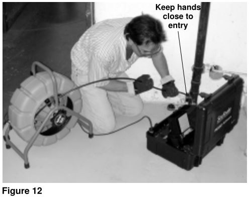
- Properly positioning the equipment and pushing of the cable will save time, be more comfortable, and minimize the potential for equipment damage. Refer to Figures 12 and 13.a. Set the monitor in an area where it is unlikely to fall, and where it can be viewed while you are pushing the camera. A good location is right next to the cleanout or entry point. Be sure to keep it from getting wet.b. Set the reel about 3′ to 5′ (1-2 meters) from the entry. This will provide ample cable to grasp and will develop momentum without having a lot of slack dragging on the ground. Slack can be alleviated by putting friction on the reel using the brake. If it is set correctly, push cable will only come off the reel when you pull on it.c. When pushing, the end of your stroke should be as close to the entry as possible. Standing too far back with an excess of cable between your hands and the entry may cause the cable to fold on itself outside the entry and damage the cable (Figure 12). d. Folding the push cable on the sharp edge of an entry can cause it to snap. Extreme caution must be used to minimize the chance of bending the push cable on sharp corners. This can cause push cable failure, and all operators should be aware of this. If the camera just does not seem to want to go any farther, DO NOT FORCE THE CAMERA! If another entry is available, try it or run water down the line as explained below. See Figure 13.NOTE! Hands should be close to the line opening. DO NOT catch the cable on the edge of an entry and continue to push.
- Always try to run water down the pipe undergoing inspection. This will keep the system much cleaner, and allow you to push noticeably farther with less friction. This will also help you locate the bottom of the pipe. This can be accomplished by feeding a hose with a small amount of flow into the entry or occasionally flushing a toilet that drains to the pipe. If the water is preventing you from seeing an area of importance, temporarily turn it off.
- When inspecting a pipe, it is usually necessary to give a little extra push in the bends. Back the camera head approximately 8″ from the bend, if necessary, and give it a quick push, “popping” the camera through a turn, using the least amount of force required. Try to be as gentle as possible, and do not hammer or snap the camera head through corners. After some practice, you may learn that the best way to inspect a section of pipe is to push the camera through quickly, then draw the camera back home slowly and evenly. It is always easier to control the camera when pulling than when pushing.
- Make sure the sapphire window is clean prior to entry. Some users claim that a slight film of detergent on the lens minimizes the possibility of grease sticking to the port. If necessary, take advantage of any standing water in the pipe to wash the front of the camera by jiggling it in the water.
- Take advantage of the lighting to keep track of where the camera is headed. If the particular pipe you are inspecting is easier to evaluate with other than the maximum lighting, periodically maximize the lighting (using the dimmer knob) to get a look at what lies ahead. Be aware of any obstructions, such as a crushed section of pipe or excessive hard build-up, that may prevent retrieval of the camera.
- When you place the camera head into the pipe remember, as the materials of pipe vary, it will be necessary to adjust the lighting settings to maximize picture quality. For example, white PVC pipe requires less lighting than black ABS. As experience is gained with the system, operators will learn that slight adjustments in these settings can highlight problems within a pipe. Always use the minimum illumination required to prevent excessive heat build-up and to maximize picture quality.
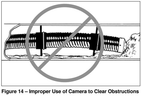
- Adjustment of the contrast and brightness settings on the monitor, as well as the light dimmer after the camera is within the pipe, can greatly increase picture quality. This is particularly important when your customer is supervising, and when making recordings. WARNINGDo not clear obstructions with the camera head! This may cause premature failure to your camera head. The SeeSnake ® is a diagnostic tool that identifies problems. Other tools should be used to make effective repairs. It should never be used to clear obstructions. See Figure 14.
- Whenever possible, lay the system on its back feet for even greater stability. This is also preferred when on a rooftop (entry through a roof vent), over- head entry, or hillside. See Figure 15.
- If local 120V (or 230V) AC power for the monitor is not available, you can operate the system using a voltage converter that plugs into your vehicle’s cigarette lighter. They convert your vehicles 12 volt DC to 120 volts (or 230V) AC.
- The system can travel through multiple 45 and 90 degree bends and wyes. Do not, however, try to force it through a P-trap or Tee if there is a large amount of resistance.
- If you are planning to use line locating equipment with your camera, be sure to use only SeeSnake ® in-line transmitters. The SeeSnake ® transmitter is specifically designed for years of service, and does not interfere with the camera’s ability to travel bends. Taping a non-SeeSnake ® transmitter to the push cable will interfere with the camera’s ability to negotiate bends and endanger the transmitter – as well as the camera head – to getting hung-up in the line.
- Do not attempt to remove or store push cable on the reel solely by turning the reel itself. Release the brake enough so that you can manually push or pull cable from the reel and wind or unwind it. If for some unusual reason the drum should not turn, do not try to pull the push cable out of the reel. This will force the cable to collapse down around the hub causing un- necessary stress on the cable.
- Be careful in Tee-entries not to fold the camera back on itself, this could cause the camera to stick.CAUTIONThe camera head can get HOT! When finished with your inspection, or if taking a prolonged break in the middle of the inspection, turn off the system.
- If the camera sits in a pipe, or any enclosed environment, heat will build-up. This may lead to the camera head overheating which will cause fuzzy lines to appear on the monitor. In the event this happens, turn off the system, remove the camera from the pipe (or enclosed environment) and let the camera head cool for 10 to 15 minutes. Running water into the line will also help cool the camera head. Always use the minimum illumination required to maximize picture quality and to avoid excessive heat build-up.
- In the very unlikely event that you encounter problems with your system during a job, the system is designed to let you troubleshoot faulty components at the job site. The procedures are covered in the “Locating Faulty Components” section below. One tip that may help you finish the job: if you isolate the problem to the hub, you can disconnectthe push cable at the dry-end, remove all the cable from the drum and pay out all the cable in a convenient location. Disconnect the system cable at the back side of the hub and connect the dry-end push cable connector to the system cable connector. Although this may be inconvenient, it will allow you to finish the job. When disconnecting and joining the connectors, be sure to pull/push the connectors straight until fully unseated/seated. Never twist connectors. Twist only the locking sleeves.
- Ask customers what is in the line, or what the line is used for, prior to putting the camera into the line. Avoid lines containing harsh solvents, chemicals, an electrical charge and excessive heat.
 d. Folding the push cable on the sharp edge of an entry can cause it to snap. Extreme caution must be used to minimize the chance of bending the push cable on sharp corners. This can cause push cable failure, and all operators should be aware of this. If the camera just does not seem to want to go any farther, DO NOT FORCE THE CAMERA! If another entry is available, try it or run water down the line as explained below. See Figure 13.NOTE! Hands should be close to the line opening. DO NOT catch the cable on the edge of an entry and continue to push.
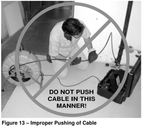
NOTE! Never use solvents to clean any part of the system.NOTE! See the Video Tape that came with your system for valuable Tips and Tricks on how to handle different situations.
Transportation & Storage
- Slip the camera into the reel with the rest of the push cable. Turn the brake clockwise enough so that the reel does not rotate unless you manually turn it.
- Unplug the SeeSnake System Cable from the CCU by turning the locking sleeve counter clock wise and then pulling the connectors straight out from each other. Wrap the cable loosely onto its storage hooks located on the frame.
- If space allows, the reel/frame should be laid on its back during transportation and use. You will notice that there is a second set of feet (three) on the back of the reel where the System Cable is stored. If there is not enough space to lay the system on its back, stand it up and run a strap or cord through the frame and secure it to the vehicle.
- Close the sunshade over the screen of the monitor and stow the line (power) cord.
- Keep spare parts, tools, and this operator’s manual secure in a work bag to protect them when not in use.
- When possible, keep the system stored in a cool, safe place. Pointing the camera into the sun or a high powered light source can damage the imaging chip.
Maintenance and Cleaning
Preventative Maintenance
Camera Head
- The camera head requires little maintenance, other than keeping the LED ring and sapphire window clean. Use a soft nylon brush, mild detergent, and rags and sponges from the camera head up to (but not including) the CCU.
- When cleaning the camera, do not use scraping tools as they may permanently scratch these areas. NEVER USE SOLVENTS to clean any part of the system. Substances like acetone and other harsh chemicals can cause cracking of the LED ring, which could affect waterproofing.
- As you use the system more and more, you may be surprised to find that scratches on the LED ring will have a minimal effect on the performance of the lighting. DO NOT sand the LED ring to remove scratches, as it is part of the watertight housing.
- Another good way to extend the life of the camera is to avoid removing obstructions from pipe with the camera head. See Figure 14.
Spring AssemblyThe spring assembly is the area where foreign matter is most likely to accumulate. Within the spring is the splice between the push cable and a connector. Should sharp objects or harsh chemicals be allowed to remain in this area for long periods, they may wear on these components. Stretch the spring end-to-end as far as the internal safety cables allow to check this area. Stretch again and stir in a bucket of warm water and mild detergent to flush this area.
Push Cable, Reel/FrameThe push cable and reel/frame require almost no maintenance. (Of course, a clean system will last longer and be more impressive to your customers.) It is important, however, to keep the push cable clean to spot any excessive cuts or abrasions, while making it much easier to grasp and push.
NOTE! Whenever you are retrieving push cable into the reel, an excellent way to cut down on cable grime is to run it through a rag in the last hand that touches the cable as it enters the reel.
- For thorough cleaning, stand the reel upright and fill the bottom of the drum with lukewarm water and a mild detergent. Spin the drum to loosen the grime. Remove the water, pull out the cable, and run a rag over the cable as you feed it back into the drum.NOTE! Never fill the drum while the unit is tipped on its back. Water can enter the hub and damage the slip rings.
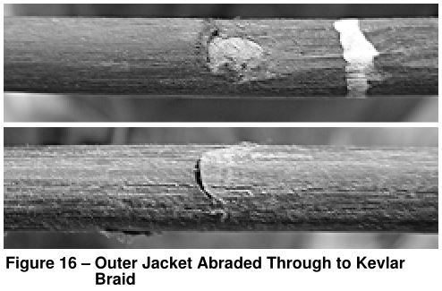
- Visually inspect the cable for cuts and abrasions as you feed it back into the drum. If the outer jacket is cut or abraded through to the yellow Kevlar beneath, the cable should be replaced or repaired (re-terminated). (See Figure 16)
- In most cases it’s best to service a damaged cable as soon as possible, but there may be some exceptions (when a cable is old and worn or when a retermination repair would remove too much cable, for example). Call Ridge Tool Technical Services to discuss your situation and develop an appropriate plan of action.NOTE! A damaged cable will absorb water and allow it to “wick” along the inside. When the cable is reterminated, the entire wet portion of cable must be cut off to allow for a proper termination onto a dry section of the cable. Although the system may remain operable for a long period of time with damaged (wet) cable, continued use may result in significantly more cable being cut off when a repair is finally needed.
- In an emergency you may wrap the damaged area of cable with duct or automobile hose tape to help minimize the amount of water entering the cable. This is not a fix and should only be used in an emergency (if your cable becomes damaged during an inspection and you need to complete the job, for example).
Camera Control UnitThe CCU requires a little more care. The same is true for any monitor in the field. Unlike the rest of the system, the CCU’s are not waterproof. Clean them with a damp cloth, and ensure foreign matter does not get into any cooling vents. Always avoid dropping or shocking these components. See your CCU Manual for complete instructions.
Corrective Maintenance
Removing Camera Head
![]()
WARNINGBefore removing the camera head for the first time, be sure to read the following instructions. Bending or twisting the camera head connectors will lead to premature failure and is not covered by warranty. Do not bend or twist connectors! Twist only the Locking Sleeves. If you need additional assistance, please call RIDGE Tool’s Technical Service 800-519-3456 before proceeding.
The system has been designed so that the camera head can be removed for troubleshooting. To remove the camera head, the procedure below must be followed:
- Pay out enough cable to place the camera and spring assembly on a work bench or other convenient work area. Set the brake to prevent the reel from spinning.
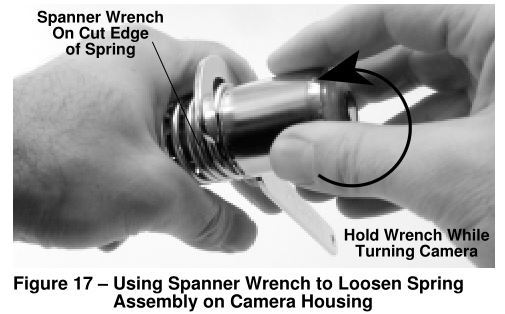
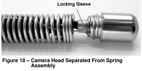
- Locate the spanner wrench that was provided with the system and hook the cut end of the spring (directly behind the camera head) with the business end of the spanner. The hand holding the spanner wrench should remain still while turning the camera off the spring with the other hand. See Figure 17. The camera should now be hanging by its locking sleeve and safety cables. See Figure 18.
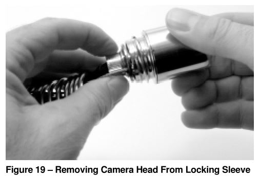
- Grasp the ribbed portion of the locking sleeve with one hand and the camera with the other. Rotate the ribbed portion of the sleeve (counter-clockwise when camera is viewed from the rear) to unscrew it from the camera housing threads while holding the camera head still with the other hand. If the locking sleeve is difficult to turn, get it started with a pair of pliers whose jaws have been wrapped in electrical tape to prevent scarring the locking sleeve. Do not crush or deform the locking sleeve by exerting excessive pressure. Be sure not to let the safety cables twist more than one rotation.The design minimizes the chance of this happening; however, it may be necessary to hold the safety cables in such a manner that when you turn the locking sleeve, you aren’t turning the safety cables. See Figure 19. WARNINGDO NOT TWIST THE CAMERA! TWIST ONLY THE LOCKING SLEEVE!
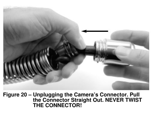
- When the locking sleeve is completely unscrewed from the camera housing female threads, the connector should automatically disengage from the camera. If this does not occur, grab the locking sleeve and connector in one hand, the camera head in the other, and pull them straight out of the back of the camera. DO NOT twist the connectors! Be sure to separate connectors by pulling straight! See Figures 19 and 20.
Re-Installing Camera Head
- Lay out enough cable to lay the spring assembly on a convenient work area and tighten the brake.
- Plug the connector and locking sleeve into the camera head, making sure that the guide pins/sockets are aligned. Be sure to fully seat the connectors without any twisting.
- Once the connectors are fully seated, grasp the camera head with one hand and turn the ribbed portion of the locking sleeve to screw it into the back of the camera. Be sure not to let the safety cables twist more than one rotation. The design minimizes the chance of this happening; however, it may be necessary to hold the safety cables in such a manner that when you turn the locking sleeve, you aren’t turning the safety cables.IMPORTANT! Do Not twist the camera head or coil cord! Turn only the locking sleeve!
- Once the locking sleeve is tight into the back of the camera, and the safety cables are parallel to each other, install the spring assembly onto the threads on the camera housing exterior. To do this, turn the camera head one rotation in the counter clockwise direction until the threads properly align; then rotate the camera head clockwise onto the spring assembly. This method will help keep the safety cables from twisting inside the spring. Be sure to use only your hands (i.e. no tools) when screwing the camera onto the spring.
NOTE! The camera head will be properly mounted when the end of the spring is snug between the camera and the thread (not so far that it begins to raise off the threads) and you cannot manually unscrew the camera.
Locating Faulty Components
The basic idea in troubleshooting the system is to use the camera head to eliminate suspected components. Here are the areas we will try to isolate the fault to: camera head, reel/frame, systems cable, CCU. As an example assume that the symptom is NO VIDEO, NO LIGHTS.
- Remove the camera from the spring assembly. See CORRECTIVE MAINTENANCE, “Removing Camera Head’ section above.
- With the system set up for operation, plug the camera head directly into the connector on the CCU where the system cable is usually connected. Turn on the system and check the monitor for a picture. If there is a good picture with proper lighting, the problem is somewhere between the system cable and the spring assembly. Proceed to step 4. If there is no picture, the problem is probably in the camera head or CCU.
- To virtually eliminate the monitor, play a tape on your monitor with a VCR through the video-in jack on your monitor (VCR – video-out; monitor – video-in). If you get a good picture, it is almost certain the problem is in the camera head. The CCU is more complicated to troubleshoot, so contact RIDGE Tool Technical Service at 800-519-3456.
- Plug the system cable into the connector on the CCU. Unplug the other end of the system cable from where it plugs into the reel-hub by unscrewing the locking sleeve and pulling the connectors straight out, and plug the camera head into this end. Turn on the system and check the monitor. If you get the video and lights back, the problem is likely in the push cable or hub. If there is no picture, the system cable is the likely fault.
- Once you suspect a component, contact RIDGE Tool Technical Service at 800-519-3456. We will establish a plan of action to get your system back on line. One tip that may help you finish the job: if you isolate the problem to the hub, you can disconnect the push cable at the dry-end, remove all the cable from the drum and pay out all the cable in a convenient location. Disconnect the system cable at the back side of the hub and connect the dry-end push cable connector to the system cable connector. Although this may be inconvenient, it will allow you to finish the job. When disconnecting and joining the connectors, be sure to pull/push the connectors straight together until fully seated. Never twist connectors. Twist only the locking sleeves.
- For additional troubleshooting suggestions, please refer to Chart 1 at the end of the manual.
Options
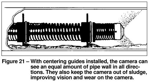
Centering GuidesThe centering guides are designed to help center the camera in various sized pipes, and also help keep the camera out of the bottom sludge. Picture quality is improved as they help position the camera towards the middle of the pipe. This allows the camera to see an equal amount of the pipe wall in all directions. Centering guides also help in larger pipes by bringing the camera closer to the pipe’s center and raising the camera out of the sludge that is often found below the water line. Keeping the camera off the bottom of the pipe keeps the front of the camera cleaner, longer. See Figure 21.
It is recommended that guides be used whenever possible as they protect the camera from wear and tear. However, if you are having trouble going further in a particular pipe, try it without the guides. The best advice is to experiment with local conditions and decide what is best for the given job. For example, you may find that placing two centering guides near the front end of the camera may bias the camera head upward. This could be beneficial if you need to see the top of the pipe during your inspection.
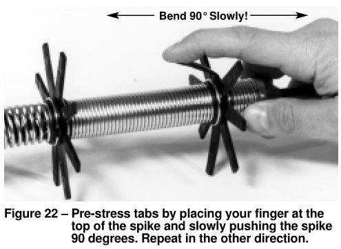
Centering guides should be pre-strained prior to use for increased flexibility. To do this, bend the spikes back and forth a few times before use. It is best if you gently bend the spikes slowly from the tip (not the base) in one direction, then in the other. See Figure 22.
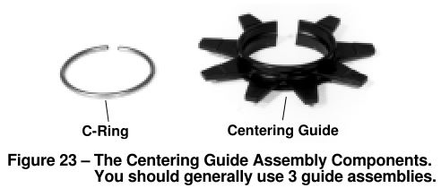
The centering guide assembly consists of two parts – the steel c-ring and the plastic centering guides. See Figure 23.
To Install the Centering Guide Assemblies:
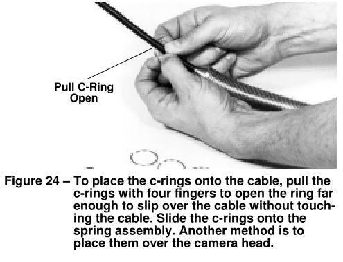
- Position the c-rings onto the spring assembly. This can be accomplished by either placing the c-rings: a) onto the push cable just behind the tapered end of the spring assembly; or b) sliding them over the camera head. Either method works well. If you use method a), be sure to open the ring far enough to avoid “scarring” the cable. See Figure 24. Regardless of the method, place all c-rings onto the spring assembly before installing the first centering guide. You will need 2 c-rings for each centering guide, and 3 centering guide assemblies generally work best in applications. However, we recommend you experiment to find the best methods for local conditions.
- Place the centering guide over the spring assembly. You will notice the centering guide has a cut through one side so the guide can be opened to slide over the spring assembly.
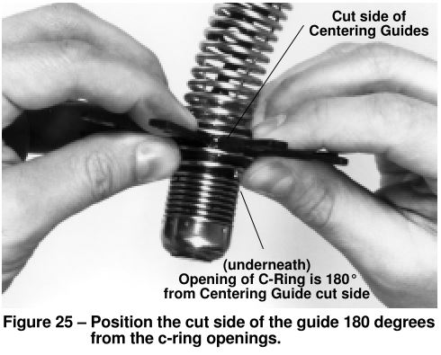
- Position the cut side of the centering guide 180 degrees from the opening in the c-rings. See Figure 25.
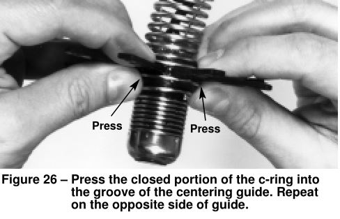
- Press the closed portion of the c-ring into the grooved portion of the centering guide. The C-ring will snap in place. Repeat with other c-ring on the other side of the centering guide. See Figure 26.
To Remove the Centering Guide Assemblies:
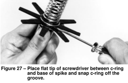
- You will need a flat blade screw driver. Place the flat tip of the screwdriver between the c-ring and the base of the spike. Pry or snap the ring off. Repeat on the other c-ring. See Figure 27.
- Remove the centering guide, and then slide the c-rings off the cable. Be sure to open the c-rings far enough to avoid “scarring” the cable. An alternative method is to slide the c-rings over the camera head.
Installing the SeeSnake Centering Guides
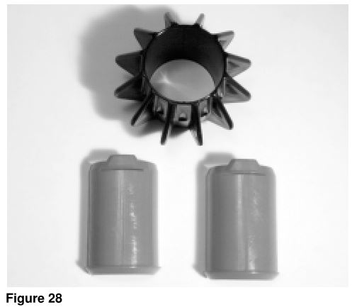
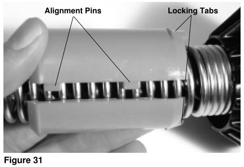
The SeeSnake snap-on pipe guide consists of the following parts (Figure 28):• 1 ball guide• 1 top sleeve (with alignment pins)• 1 bottom sleeve (with alignment slots)
Installation
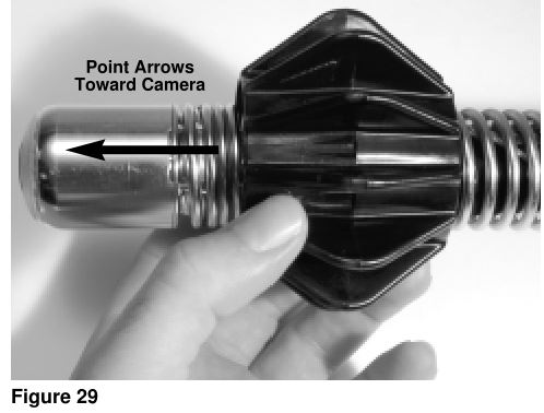
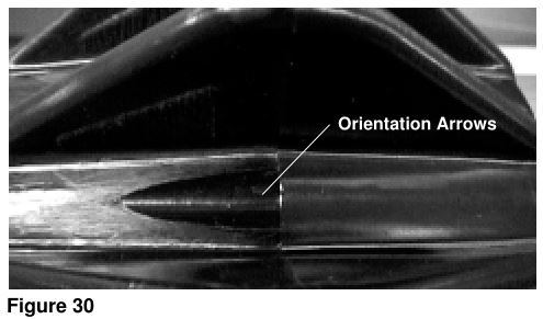
- Place the ball guide over the SeeSnake camera spring with the orientation arrow heads pointing toward the camera (Figure 29 and Figure 30).
- Place the sleeves over the spring between the ballguide and camera head with the locking tabs pointedtoward the guide ball (Figure 31).
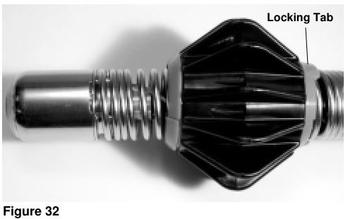
- Slide ball guide over the sleeves until the locking tabs engage with the rear of the ball guide (Figure 32).
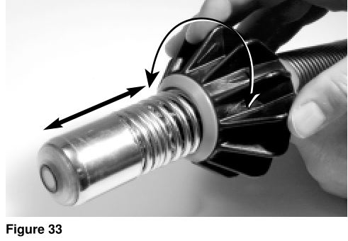
AdjustmentIf necessary, adjust the guide’s position on the spring by turning the guide (Figure 33).
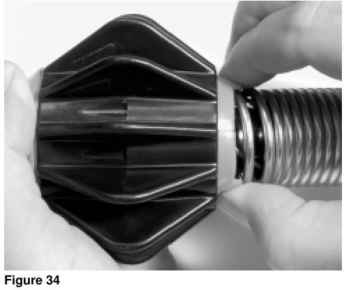
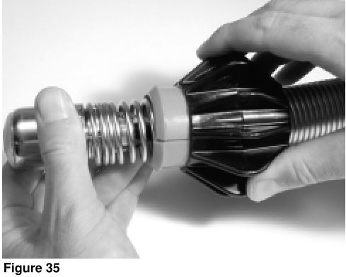
RemovalDepress the locking tab on both sleeves simultaneously, either with fingers (Figure 34) or with channel lock pliers, and slide the ball guide off the sleeves (Figure 35).
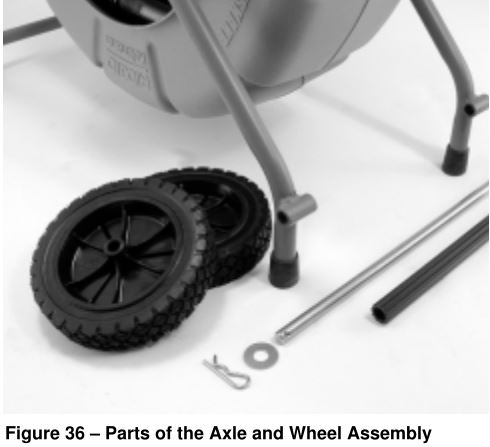
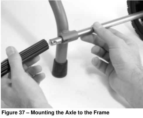
Appendix A – Installing the Standard SeeSnake Wheels
Service and Repair
![]()
WARNING
Tool should be taken to a RIDGID Independent Authorized Service Center or returned to the factory. All repairs made by Ridge service facilities are warranted against defects in material and workmanship.
If you have any questions regarding the service or repair of this machine, call or write to:
Ridge Tool CompanyTechnical Service Department400 Clark StreetElyria, Ohio 44035-6001Tel: (800) 519-3456E-mail: [email protected]
For name and address of your nearest Independent Authorized Service Center, contact the Ridge Tool Company at (800) 519-3456 or http://www.ridgid.com or www.seesnake.com
Chart 1 Troubleshooting
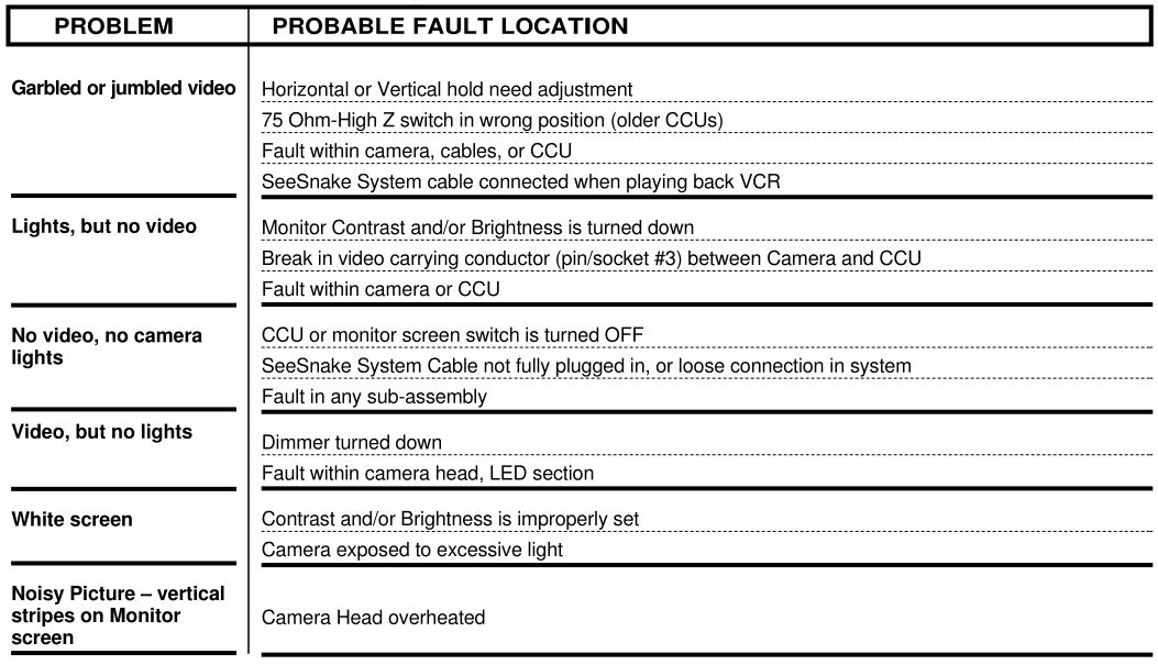
If further assistance is needed, please call RIDGE Tool Technical Service at (800) 519-3456. Additional information may be available at www.ridgid.com or www.seesnake.com
RIDGID Kollmann Standard and Mini SeeSnake Diagnostic Equipment User Manual – RIDGID Kollmann Standard and Mini SeeSnake Diagnostic Equipment User Manual –
[xyz-ips snippet=”download-snippet”]