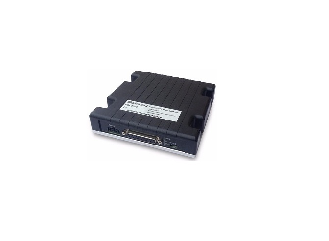
RoboteQ Advanced Features 2 x 60A or 1 x 120A Brushless DC Motor Controller with USB and CAN User Manual
Applications
- Automatic Guided Vehicles
- Small Electric Vehicles, Electric Bikes
- Terrestrial and Underwater Robotic Vehicles
- Police and Military Robots
- Hazardous Material Handling Robots
- Balancing Robots
- Telepresence Systems
- Animatronics
Key Features
- USB, Serial, 0-5V Analog, or Pulse (RC radio) command modes
- One RS232 serial port · CAN bus interface up to 1Mbit/switch multiple protocol support
- RS485
- Optional Ethernet interface
- Auto switch between Serial, USB, CAN, Analog, orPulse based on user-defined priority
- Built-in dual 3-phase high-power drivers for twobrushless DC motor at up to 60A
- Output channels can be paralleled in order to drive asingle motor at up to 120A
- Multiple Motor Operating mode– Trapezoidal with Hall Sensors– Sinusoidal with Encoders– Sinusoidal with Hall Sensors
- Support for absolute angle encoders · sin/cos analog
- SSI (A & T version)
- Resolver (A & T version)
- Field Oriented Control in Sinusoidal modes
- Full forward & reverse motor control. Four quadrant operation. Supports regeneration · Operates from a single 10V-60V power source
- STO – Safe Torque Off support (T-version) – Certification No. M6A 104504 0001 Rev. 00 · Design compliant/approval UL 61800-5-1
- Programmable current limit up to 60A (120Aon single channel version) per motor for protecting controller, motor, wiring and battery.
- Separate connector for Hall Sensors
- Accurate speed and Odometry measurement using Hall Sensor or Encoder data
- Up to 8 Analog Inputs for use as command and/or feedback
- Up to 8 Pulse Length, Duty Cycle or Frequency Inputs for use as command and/or feedback
- Up to 10 Digital Inputs for use as Deadman Switch, Limit Switch, Emergency stop or user inputs
- Inputs for up to 2 Quadrature Encoders
- 4 general purpose 24V, 1.5A output for brake release or accessories
- Selectable min, max, center and dead band in Pulse and Analog modes
- Selectable exponentiation factors for each command inputs
- Trigger action if Analog, Pulse or Hall counter capture are outside user selectable range (soft limit switches)
- Open loop or closed loop speed control operation
- Closed loop position control with encoder, hall sensors, analog or pulse/frequency feedback
- Torque mode · PID control loop
- Built-in Battery Voltage and Temperature sensors
- Optional backup power input for powering safely the controller if the main motor batteries are discharged
- Power Control wire for turning On or Off the controller from external microcomputer or switch
- No consumption by output stage when motors stopped
- Regulated 5V output for powering RC radio, RF Modem, sensors or microcomputer
- Separate Programmable acceleration and deceleration for each motor
- Ultra-efficient 2.5 mOhm ON resistance MOSFETs (1.25 mOhm on Single Channel)
- Stall detection and selectable triggered action if Amps is outside user-selected range
- Short circuit protection
- Overvoltage and Undervoltage protection
- Watchdog for automatic motor shutdown in case of command loss
- Overtemperature protection
- Diagnostic LED
- ABS plastic enclosure with heat conducting bottom plate
- Efficient heat sinking. Operates without a fan in most applications.
- Dustproof and weather resistant. IP40 rating
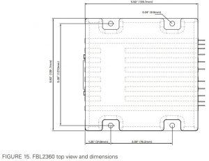
- Power wiring 0.25″ Faston tabs · 5.5″ (139.7mm) L, 5.5″ W (139.7mm), 1.0″ (25mm) H
- -40o to +85o C operating environment
- 1 lbs (500g)
- Easy configuration, tuning and monitory using provided PC utility
- Field upgradeable software for installing latest features via the internet Orderable Product References
- Field upgradeable software for installing latest features via the internet Orderable Product References
Specifications and Listings
Controller is designed and build to comply with UL and IEC specifications and standards, but is approved only under the mentioned standards on this datasheet.
Orderable Product References
| Reference |
Number of Channels |
Amps/Channel |
Volts |
Ethernet |
STO |
| FBL2360(A) |
2 |
60 |
60 |
No |
No |
| FBL2360(A)S |
1 |
120 |
60 |
No |
No |
| FBL2360T |
2 |
60 |
60 |
No |
Yes |
| FBL2360TS |
1 |
120 |
60 |
No |
Yes |
| FBL2360E |
2 |
60 |
60 |
Yes |
No |
| FBL2360ES |
1 |
120 |
60 |
Yes |
No |
| FBL2360TE |
2 |
60 |
60 |
Yes |
Yes |
| FBL2360TES |
1 |
120 |
60 |
Yes |
Yes |
Important Safety DisclaimerDangerous uncontrolled motor runaway condition can occur for a number of reasons, including, but not limited to: command or feedback wiring failure, configuration error, faulty firmware, errors in user script or user program, or controller hardware failure. The user must assume that such failures can occur and must make his/her system safe in all conditions. Roboteq will not be liable in case of damage or injury as a result of product misuse or failure.
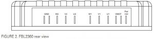
Power Wires Identifications and Connection
Power connections are made by means of faston tabs located at the back of the controller.
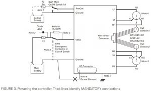
 The diagram below shows how to wire the controller and how to turn power On and Off.
Important WarningCarefully follow the wiring instructions provided in the Power Connection section of the User Manual. The information on this datasheet is only a summary.
Mandatory ConnectionsIt is imperative that the controller is connected as shown in the above diagram in order to ensure a safe and trouble-free operation. All connections shown as thick black lines line are mandatory. The controller must be powered On/Off using switch SW1on the PwrCtrl tab. Use a suitable high-current fuse F1 (check table 12) as a safety measure to prevent damage to the wiring in case of major controller malfunction.
Emergency Switch or ContactorThe battery must be connected in permanence to the controller’s Vmot tabs via a high-power emergency switch or contactor SW2 as additional safety measure. The user must be able to deactivate the switch or contactor at any time, independently of the controller state.
Electrostatic Discharge ProtectionIn accordance with IEC 61000-6-4, Roboteq Motor Controllers are designed to withstand ESD up to 4kV touch and 8kV air gap. This protection is implemented without any additional external connections required.Some specifications, such as EN12895, require a higher level of protection. To maximize ESD protection, up to 8kV touch and 15kV air gap, you may connect the metallic heat sink of the controller to your battery negative terminal. See App Note 062918 for example connections.
Precautions and Optional ConnectionsNote 1: Backup battery to ensure motor operation with weak or discharged batteries, connect a second battery to the Power Control wire/terminal via the SW1 switch.Note 2: Use precharge 1K, 0.5W Resistor to prevent switch arcing.Note 3: Insert a high-current diode to ensure a return path to the battery during regeneration in case the fuse is blown.Note 4: Optionally ground the Vmot tabs when the controller is Off if there is any concern that the motors could be made to spin and generate voltage in excess of 60V.Note 5: Connect the controller’s bottom plate to a wire connected to the Earth while the charger is plugged in the AC main, or if the controller is powered by an AC power supply.Note 6: Beware not to create a path from the ground pins on the I/O connector and the battery minus terminal.
Single Channel Wiring
On the Single Channel FBL2360S, the each of the motor wire must be connected to both output tabs of the same letter as shown in the figure below. Use the Encoders and/or Hall sensors of Channel 1 for operation.
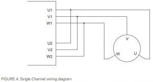 Important WarningThis wiring must be done only on the single channel version of the controller. Paralleling the wires on a dual channel product will cause permanent damage. Verify that your controller is an FBL2360S before you wire in this manner.
Use of Safety Contactor for Critical Applications
An external safety contactor must be used in any application where damage to property or injury to person can occur because of uncontrolled motor operation resulting from failure in the controller’s power output stage.
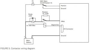 The contactor coil must be connected to a digital output configured to activate when “No MOSFET Failure”. The controller will automatically deactivate the coil if the output is expected to be off and battery current of 1A or more is measured for more than 0.5s. This circuit will not protect against other sources of failure such as those described in the “Important Safety Disclaimer”.
Controller Mounting
During motor operation, the controller will generate heat that must be evacuated. The published amps rating can only be fully achieved if adequate cooling is provided. Good conduction cooling can be achieved by having the bottom surface of the case making direct contact with a metallic surface (chassis, cabinet). The mounting has to be like that, so that the thermal-safety limits are not exceeded.
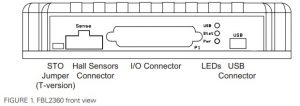
Hall Sensors Connection
Connection to the Hall Sensors is done using a special connector on the front side of the controller. The Hall sensor connector is a 10-pin Molex Microfit 3.0, ref. 43025-1000. Pin assignment is in the table below.

|
TABLE 1 |
|||||
|
Pin Number |
1 |
2 |
3 |
4 |
5 |
| Row Ch1 |
5V |
Hall 1 C |
Hall1 B |
Hall 1 A |
Ground |
| Row Ch2 |
5V |
Hall 2 C |
Hall 2 B |
Hall 2 A |
Ground |
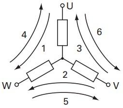
Hall Sensor vs Motor Output Sequencing
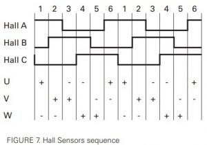
The controller requires the Hall sensors inside the motor to be 120 degrees apart. The controller’s 3-phase bridge will activate each of the motor winding according to the sequence shown in the figure below.
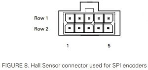
Connection to SPI Absolute Encoder
In Sinusoidal Mode, the FBL2360 and FBL2360S models can use motors equipped with absolute angle sensors with SPI interface, such as found on the BL167 or BL90 motors from Micromotor. When enabled, the SPI signals are found on the 10-pin Molex connector that is otherwise used for the Hall Sensors. The controller issues a clock and select signal. When two motors are used, these signals must be connected to both sensors. Serial data from each sensor is captured on separate input pins. The SPI Encoder is not available on `A’, `T’ and `E’ versions of Roboteq products.

|
TABLE 2 |
|||||
| Pin Number |
1 |
2 |
3 |
4 |
5 |
| Row 1 |
5V |
NC |
NC |
Sel |
GND |
| Row 2 |
5V |
Clock |
Data 2 |
Data 1 |
GND |
In Sinusoidal Mode, the controller can use motors equipped with absolute angle sensors with SSI interface. When enabled, the SSI signals are found on the 10-pin Molex connector that is otherwise used for the Hall Sensors. The controller issues a differential clock signal and expects a 12-bit differential data signal from the encoder. When two motors are used, these signals must be connected to both sensors. Serial data from each sensor is captured on separate input pins. The SSI Encoder is only featured on `A’, `T’ and `E’ versions of Roboteq products.
|
TABLE 3 |
|||||
| Pin Number |
1 |
2 |
3 |
4 |
5 |
| Row 1 |
5V |
CLK – |
Data 2 – |
Data 1 – |
GND |
| Row 2 |
5V |
Clock + |
Data 2 + |
Data 1 + |
GND |
Connection to Analog Sin/Cos Absolute Encoder
The FBL2360 has 4 high-speed analog inputs that can be used to capture absolute angle position from resolvers or magnetic sensors with sin/cos voltage outputs. The signal must be 0-5V max with the 0 at 2.500V. The table below shows the signals assignment on the 25-pin connector.
|
TABLE 4 |
||
| Signal |
Pin Number |
Pin Name |
| Sin 1 |
9 |
ASIN 1 |
| Cos 1 |
10 |
ACOS 1 |
| Sin 2 |
24 |
ANA7/ASIN2 |
| Cos 2 |
12 |
ANA8/ACOS2 |
Connecting Resolver
Resolver wiring is similar to a Sin/Cos sensor with the addition of an excitation signal. Diagram below shows the necessary connections.

|
TABLE 5 |
||
| Signal |
Pin Number |
Pin Name |
| Sin1 |
9 |
ASIN1 |
| Cos1 |
10 |
ACOS1 |
| Sin2 |
24 |
ANA7/ASIN2 |
| Cos2 |
12 |
ANA8/ACOS2 |
| Exc |
17 |
ANA4/EXC |
| GND |
1-5 or 13 |
GND |
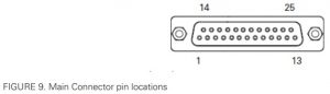
Commands and I/O Connections
Connection to RC Radio, Microcomputer, Joystick and other low current sensors and actuators is done via the DB25 connector. The functions of many pins vary depending on controller model and user configuration. Pin assignment is found in the table below.
|
TABLE 6 |
|||||||||
|
Connector Pin |
Power |
Dout |
Com |
Pulse |
Ana |
Dinput |
Enc |
Hall (4) |
Default Config |
|
1 |
GND |
||||||||
|
14 |
5VOut |
||||||||
|
2 |
RS TxD |
RS232Tx |
|||||||
|
15 |
RC1 |
ANA1 |
DIN1/ STO1 (2) |
Hall1A |
RC Radio1 (3) |
||||
|
3 |
RS RxD |
RS232Rx |
|||||||
|
16 |
RC2 |
ANA2 |
DIN2/ STO2 (2) |
Hall1B |
RC Radio2 (3) |
||||
|
4 |
RC3 |
ANA3 |
DIN3 |
Hall1C |
AnaCmd1 (1) |
||||
|
17 |
RC4 |
ANA4/EXC |
DIN4 |
Hall2A |
AnaCmd2 (1) |
||||
|
5 |
GND |
||||||||
|
18 |
DOUT1 |
Motor Brake 1 |
|||||||
|
6 |
DOUT2 |
Motor Brake 2 |
|||||||
|
19 |
DOUT3 |
Contactor |
|||||||
|
7 |
DOUT4 |
Unused |
|||||||
|
20 |
CANH |
Unused |
|||||||
|
8 |
CANL |
Unused |
|||||||
|
21 |
RC5 | ANA5 | DIN5 | ENC2A | Hall2B |
Unused |
|||
|
9 |
ASIN1 | DIN9 |
Unused |
||||||
|
22 |
RC6 | ANA6 | DIN6 | ENC2B | Hall2C |
Unused |
|||
|
10 |
ACOS1 | DIN10 |
Unused |
||||||
|
23 |
485 + |
RS485 + |
|||||||
|
11 |
485 – |
RS485 – |
|||||||
|
24 |
RC7 | ANA7/ ASIN2 | DIN7 | ENC1A |
Unused |
||||
|
12 |
RC8 | ANA8/ ACOS2 | DIN8 | ENC1B |
Unused |
||||
|
25 |
5VOut |
||||||||
|
13 |
GND |
||||||||
| Note 1: Analog command is disabled in factory default configuration.
Note 2: STO functionality only available in T versions. See STO section for details. Note 3: Pulse input enable by default on firmware version prior to v2.0 Note 4: Hall inputs are activated in DB25 connector in firmware v2.0 or later and only if Molex input is configured as SSI Input. In that case user has to install 1K pull up resistor between each hall signal and 5VOut. |
Default I/O ConfigurationWhile the controller can be configured so that practically any Digital, Analog and RC pin can be used for any purpose, the controller’s factory default configuration provides an assignment that is suitable for most applications. The figure below shows how to wire the controller to two analog potentiometers, an RC radio, and the RS232 port. It also shows how to connect two outputs to motor brake solenoids and another output to an external status LED. You may omit any connection that is not required in your application. The controller automatically arbitrates the command priorities depending on the presence of a valid command signal in the following order: 1-RS232, 2-RC Pulse, 3-None. If needed, use the Roborun+ PC Utility to change the pin assignments and the command priority order.
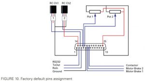
Enabling Analog Commands
For safety reasons, the Analog command mode is disabled by default. To enable the Analog mode, use the PC utility and set Analog in Command Priority 2 or 3 (leave Serial as priority 1). Note that by default the additional securities are enabled and will prevent the motor from starting unless the potentiometer is centered, or if the voltage is below 0.25V or above 4.75V. The drawing shows suggested assignment of Pot 1 to ANA1 and Pot 2 to ANA4. Use the PC utility to enable and assign analog inputs.
USB Communication
Use USB only for configuration, monitoring and troubleshooting. USB is not a reliable communication method when used in an electrically noisy environments and communication will not always recover after it is lost without unplugging and replugging the connector, or restarting the controller. Always prefer RS232 communication when interfacing to a computer. USB and CAN can operate at the same time on the FBL2360. Plugging USB to a computer will not disable CAN interface.
RS485 Communication
RS485 is an industry standard for defining serial communication. Due to its balanced signalling, RS485 is effective over distances, even if other electrical signals are present. Its stability makes it well suited to connect multiple receivers to a single network. You can operate RS485 in half-duplex mode and it is well suited for use with the Modbus protocol. On the 25-pin connector, RS485+ and RS485- pins are present.
Ethernet Communication
Ethernet communication is currently only available on the E versions of applicable Roboteq product. There is a connection port on the top of the unit for easy and rapid access. While the TCP and Modbus TCP protocols are supported, Serial is the preferred method to access all native commands.
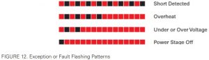
Status LED Flashing Patterns
After the controller is powered on, the Power LED will tun on, indicating that the controller is On. The Status LED will be flashing at a two second interval. The flashing pattern and colour provides operating or exception status information.
 Additional status information may be obtained by monitoring the controller with the PC utility.
Battery Backed Clock and Variables
The battery backed clock and variables feature allows accurate time/date stamping of information such as status and error reports. It is important to note that the only Roboteq products that include this feature are ones that specifically say that battery backed clock is a product feature. If your Roboteq product has displayed time/date information but the product does not specifically list the battery backed clock as a feature, then the information displayed is random and not accurate.The location of the battery is dependent on the product. However, any Roboteq product with this feature will run it on a 3V, 12.5mm coin style battery. The clock is accessible via the ^BEE commands and user input variables will remain even if the unit is powered off.Please Note: Customers will be required to install the battery for the clock (type BR-1225), themselves. Units do not ship with the battery for the Battery Backed Clock, installed.
Measured and Calculated Amps
The controller includes Amps sensors in line with the motor terminals. Motor Amps are measured with precision. Battery Amps are estimated mathematically.When motor is rotating, amps are AC. The FBL2360 measures and is rated based on RMS Amps. The table below shows the relation between the RMS current and the DC Equivalent in Sinusoidal and Trapezoidal modes. In sinusoidal mode, DC equivalent are the amps resultant from the torque (Iq) and quadrature (Id) vectors. In trapezoidal mode, they are the DC amps that flow through the two coils that are active at any one time.
|
Amps RMS |
DC Equivalent |
|
|
Sinusoidal |
120A |
170A (Irms * 1.414) |
|
60A |
85A (Irms * 1.414) |
|
|
Trapezoidal |
120A |
147A (Irms * 1.225) |
|
60A |
73.5 (Irms * 1.225) |
Safe Torque Off – STO (Certification No. M6A 104504 0001 Rev 00)
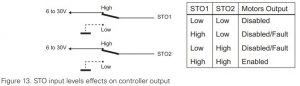
Safe Torque Off is a safe method for switching controller in a state where no torque is generated, regardless whether the controller is operating normally or is faulty. When STO is enabled, two digital inputs, DIN1 and DIN2 are remapped as STO1 and STO2. The inputs are redundant and both must have a 6V to 30V signal present at the same time in order for the Power MOSFETs to be energized. The controller will perform a self-check of the STO circuit at every power on and every time the STO inputs go from any state to both high. Once the STO hardware is verified to work, the controller will safely allow the motors to be energized. If either input is below 1V, the controller’s outputs will be disabled. The STO circuit is verified and validated and can therefore be trusted instead of external relays. See STO Manual for more information and maintenance instructions.By factory default STO functionality is disabled. It must be enabled by removing the jumper located on the controller’s PCB. STO functionality is only available in the T version of the controller.
The STO function is compliant to:
- IEC 61800-5-2:2007, SIL 3
- IEC 61508:2010, SIL 3
- IEC 62061:2005, SIL 3
- ISO 13849-1:2015, Category 3 Performance Level e
Important WarningActivating STO does lead to no more torque generation on the motor. The motor will not be actively stopped but run out. In case of a multiple fault in the power stage a rotation might occur.
Secure Connection to AMP FASTON Tabs
Power Motor and Battery connections are made via standard 250 mils (6.35mm) AMP FASTON Tabs. FASTON connectors provide a high current and very secure connection, proven over decades of use in the automotive industry. For maximum current handling, use connectors for AWG8 wires. FASTON connectors have an extremely tight fit and will not come off on their own. It is recommended, nevertheless, that the wiring is made so that the cables are never pulling the connector outward. Frequent disconnects and reconnects will eventually loosen the connector’s grip on the tab. If frequent disconnection is required, consider using Positive Lock connectors from TE Connectivity or their equivalent. These connectors have a spring-loaded tab latch pin that will lock into the hole of the male tab.
Electrical Specifications
Absolute Maximum ValuesThe values in the table below should never be exceeded, permanent damage to the controller may result.
|
TABLE 7 |
|||||
|
Parameter |
Measure point |
Min |
Typ |
Max |
Units |
| Battery Leads Voltage |
Ground to Vmot |
60 (1) |
Volts |
||
| Reverse Voltage on Battery Leads |
Ground to Vmot |
-1 |
Volts |
||
| Power Control Voltage |
Ground to PwrCtrl wire |
60 (1) |
Volts |
||
| Motor Leads Voltage |
Ground to U, V, W wires |
60 (1) |
Volts |
||
| Digital Output Voltage |
Ground to Output pins |
30 |
Volts |
||
| Analog and Digital Inputs Voltage |
Ground to any signal pin on DB25 & Hall inputs |
30 |
Volts |
||
| RS232 I/O pins Voltage |
External voltage applied to Rx pins |
30 (2) |
Volts |
||
| Case Temperature |
Case |
-40 |
85 |
ºC |
|
| Humidity |
Case |
100 (3) |
% |
||
| Note: Only PELV/SELV voltages shall be used | |||||
| Note 1: Can be even higher because of regeneration voltage. Never inject a DC voltage from a battery or other fixed source | |||||
| Note 2: No voltage must be applied on Tx pin | |||||
| Note 3: Non condensing |
Power Stage Electrical Specifications (at 25ºC ambient)
Table 8.
|
Parameter |
Measure point |
Model |
Min |
Typ |
Max |
Units |
| Input Voltage |
Ground to Vmot |
All |
0 (1) |
60 |
Volts |
|
| Input continuous Max Current |
Power source current |
All |
80 |
Amps |
||
| Output Voltage |
Ground to U, V, W wires |
All |
0 (1) |
60 (2) |
Volts |
|
| Power Control Voltage |
Ground to Power Control wire |
All |
0 (1) |
65 |
Volts |
|
| Minimum Operating Voltage |
VBat or PwrCtrl wires |
All |
10 (3) |
Volts |
||
| Over Voltage protection range |
Ground to Vmot |
All |
5 |
60 (4) |
63 |
Volts |
| Under Voltage protection range |
Ground to Vmot |
All |
0 |
5 (4) |
63 |
Volts |
| Idle Current Consumption |
Vmot or PwrCtrl wires |
All |
50 |
100 (5) |
150 |
mA |
| ON Resistance (Excluding wire resistance) |
Vmot to U, V or W. Ground to U, V or W |
FBL2360 |
2.5 |
mOhm |
||
|
FBL2360S |
1.25 |
mOhm |
||||
| Max Current for 30s |
Motor current |
FBL2360 |
60 |
Amps |
||
|
FBL2360S |
120 |
Amps |
||||
| Continuous Max Current per channel |
Motor current |
FBL2360 |
40 (6) |
Amps |
||
|
FBL2360S |
80 (6) |
Amps |
||||
| Current Limit range |
Motor current |
FBL2360 |
10 |
50 (7) |
60 |
Amps |
|
FBL2360S |
20 |
100 (7) |
120 |
Amps |
||
| Stall Detection Amps range |
Motor current |
FBL2360 |
10 |
60 (7) |
60 |
Amps |
|
FBL2360S |
20 |
120 (7) |
120 |
Amps |
||
| Stall Detection timeout range |
Motor current |
All |
1 |
500 (8) |
65000 |
msec |
| Short Circuit Detection threshold (9) |
Between Motor wires or Between Motor wires and ground or Between Motor wires and Vmot |
FBL2360 |
125(10) |
Amps |
||
|
FBL2360S |
250 (10) |
Amps |
||||
| Motor Acceleration/ Deceleration range |
Motor Output |
All |
100 |
500(11) |
65000 |
msec |
| Power cable thickness |
Power input and output |
All |
8 |
AWG |
||
| Note 1: Negative voltage will cause a large surge current. Protection fuse needed if battery polarity inversion is possible | ||||||
| Note 2: Can be even higher because of regeneration voltage. Never inject a DC voltage from a battery or other fixed source | ||||||
| Note 3: Minimum voltage must be present on VBat or Power Control wire | ||||||
| Note 4: Factory default value. Adjustable in 0.1V increments | ||||||
| Note 5: Current consumption is lower when higher voltage is applied to the controller’s VBat or PwrCtrl wires | ||||||
| Note 6: Estimate. Limited by case temperature. Current may be higher with better cooling | ||||||
| Note 7: Factory default value. Adjustable in 0.1A increments | ||||||
| Note 8: Factory default value. Time in ms that Stall current must be exceeded for detection | ||||||
| Note 9: Controller will stop until restarted in case of short circuit detection” change with “Controller will stop until zero command given in case of short circuit detection | ||||||
| Note 10: Approximate value | ||||||
| Note 11: Factory default value. Time in ms for power to go from 0 to 100% |
Command, I/O and Sensor Signals Specification
Table. 9
|
Parameter |
Measure point |
Min |
Type |
Max |
Units |
| Main 5V Output Voltage | Ground to 5V pins on |
4.6 |
4.9 | 5.2 |
Volts |
| 5V Output Current | 5V pins on RJ45 and D Sub 15 |
200 (1) |
mA |
||
| Digital Output Voltage | Ground to Output pins | 30 |
Volts |
||
| Output On resistance | Output pin to ground |
0.25 |
0.5 |
Ohm |
|
| Output Short circuit threshold | Output pin |
1.7 |
3.5 |
Amps |
|
| Digital Output Current | Output pins, sink current | 1.5 |
Amps |
||
| Input Impedances (except DIN11-19) | AIN/DIN Input to Ground |
53 |
kOhm |
||
| Digital Input 0 Level | Ground to Input pins |
-1 |
1 |
Volts |
|
| Digital Input 1 Level | Ground to Input pins |
3 |
30 |
Volts |
|
| Analog Input Range | Ground to Input pins |
0 |
5.1 |
Volts |
|
| Analog Input Precision | Ground to Input pins |
0.5 |
% |
||
| Analog Input Resolution | Ground to Input pins |
1 |
mV |
||
| Encoder Frequency |
500 |
kHz |
|||
| Pulse durations | Pulse inputs |
20000 |
10 |
us |
|
| Pulse repeat rate | Pulse inputs |
50 |
250 |
Hz |
|
| Pulse Capture Resolution | Pulse inputs |
1 |
us |
||
| Frequency Capture | Pulse inputs |
100 |
1000 |
Hz |
|
| Note 1: Sum of all 5VOut outputs |
Operating & Timing Specifications
|
TABLE 10 |
|||||
| Parameter | Measure Point |
Min |
Typ |
Max |
Units |
| Command Latency |
Command to output change |
0 | 0.5 | 1 |
ms |
| PWM Frequency | Motor Output |
10 |
16 | 25 |
kHz |
| Closed Loop update rate | Internal |
1000 |
Hz |
||
| RS232 baud rate | Rx & Tx pins |
115200 (1) |
Bits/s |
||
| RS232 Watchdog timeout | Rx pin |
1 (2) |
65000 |
ms |
|
| Note 1: 115200, 8-bit, no parity, 1 stop bit, no flow control | |||||
| Note 2: May be disabled with value 0 |
Scripting
|
TABLE 11 |
|||||
| Parameter | Measure Point |
Min |
Typ |
Max |
Units |
| Scripting Flash Memory | Internal |
32K |
Bytes |
||
| Max Basic Language programs | Internal |
2000 |
3000 |
Lines |
|
| Integer Variables | Internal |
4096 |
Words (1) |
||
| Boolean Variables | Internal |
8192 |
Symbols |
||
| Execution Speed | Internal |
50 000 |
100 000 |
Lines/s |
|
| Note 1: 32-bit words |
Thermal Specifications
|
TABLE 12 |
|||||
| Parameter | Measure Point |
Min |
Typ |
Max |
Units |
| Case Temperature | Case |
-40 |
85 (1) |
oC |
|
| Thermal Protection range | Case |
80 |
90 (2) |
oC |
|
| Power Dissipation | Case |
70 |
Watts |
||
| Thermal resistance | Power MOSFETs to case |
0.6 |
oC/W |
||
| Humidity | Case |
95 |
% |
||
| Ambient temperature | Ambient |
55 |
oC |
||
| Pollution Degree | – | ||||
| Fast fuse to install (3) | FBL2360 (4) |
40 |
2 x 40 |
Amps |
|
| FBL2360S (4) |
2 x 40 |
Amps |
|||
| Overload motor protection | – |
Check note 5 |
|||
| Note 1: Thermal protection will protect the controller power | |||||
| Note 2: Max allowed power out starts lowering at minimum of range, down to 0 at max of range | |||||
| Note 3: There are two power terminal tabs. Fuse should be installed in both of them for safety. | |||||
| Note 4: In dual channel controller, for operating only one channel install 40A fuse and for operating both channels 2 x 40A fuse should be installed. Power source must be capable to blow the fuse instantly in case of short circuit | |||||
| Note 5: Current limiting mechanism available through firmware. External overload motor protection can be used if required (provided by user) |
STO Specifications
|
TABLE 13 |
|||||
| Parameter | Measure Point |
Min |
Typ |
Max |
Units |
| STO Input High Level |
Ground to STO input pin |
6 | 30 (1) |
Volts |
|
| STO Input Low Level | Ground to STO input pin |
0 |
1 |
Volts |
|
| STO Response Time | Input to output change | 5 |
msec |
||
| STO Operating temperature |
-20 |
55 |
ºC |
||
| STO Storage temperature |
-20 |
70 |
ºC |
||
| Humidity |
5 |
95 |
% |
||
| IP degree |
IP40 |
||||
| Operating Altitude |
2000 |
m |
|||
| Cable Length |
2 |
m |
|||
| EMC Immunity | According to IEC 61800-3 and IEC 61800-5-2 Annex E | ||||
| CE Declaration | Available at www.roboteq.com |
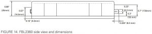
Mechanical Specifications
|
TABLE 14 |
|||||
| Parameter | Measure Point |
Min |
Typ |
Max |
Units |
| Weight | Board |
500 (1) |
g (lbs) |
||
| Power Connectors width | Terminal tab |
0.25 |
Inches |
Electrical Specification
Revision History
| Revision | Date | Additions/Changes |
| 1.1 | April 23, 2019 | Added T-version with STO support |
| 1.2 | May 21, 2019 | STO certification change |
| 1.3 | August 29, 2019 | UL certification changes |
References
[xyz-ips snippet=”download-snippet”]