ROCKVILLE 10,000-Watt Pro Rack Amplifier
IMPORTANT SAFETY INSTRUCTIONS
TO REDUCE THE RISK OF ELECTRICAL SHOCK, NEVER OPEN THE UNIT. NO USER SERVICEABLE PARTS INSIDE. WE RECOMMEND TAKING THE UNIT TO A QUALIFIED SERVICE TECHNICIAN FOR ANY REPAIRS.
- Do not expose this unit to any kind of moisture.
- Please ensure that the unit is situated in a properly ventilated area.
- Make sure cooling fan vents are free of obstructions.
- Replace fuse with one of the same type, size, and rating only.
- Do not attempt to operate this unit if the power cord has been frayed or broken.
- Do not attempt to break off or remove the ground prong. This prong is used to reduce the risk of electrical shock and fire in case of an internal short.
- Do not operate this unit if it is damaged.
- This unit is intended for indoor use only.
- During long periods of non-use, disconnect the unit from power source.
- Always mount this unit in a safe and stable manner.
- Power supply cords should be routed so that they are not likely to be walked on or pinched by items placed upon or against them, paying particular attention to the point of exit from the unit.
- To avoid unnecessary wear and to improve the unit’s lifespan, unplug the unit when not in use for extended periods of time.
Features
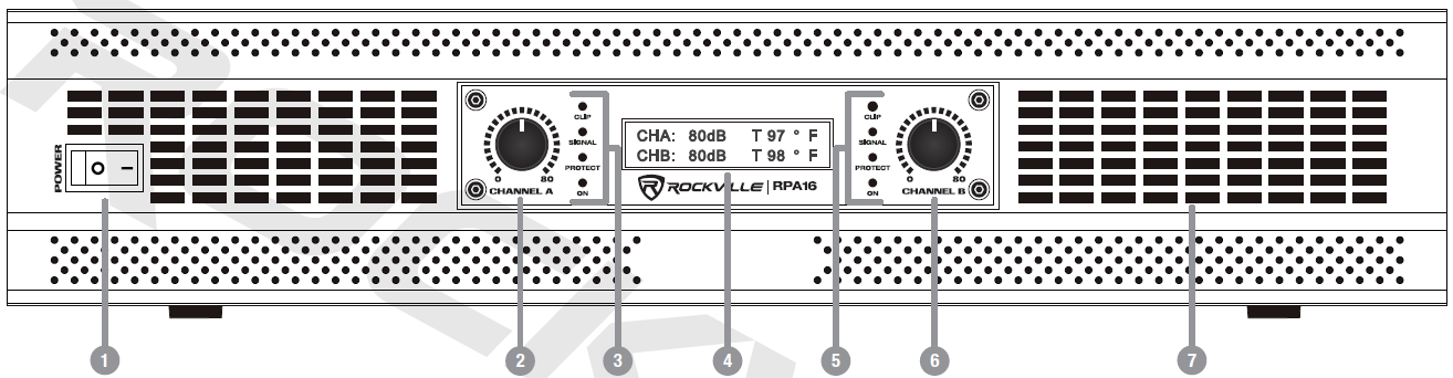
- Power On/Off Switch.
- Channel A Signal Level Adjustment Knob: Controls the level of incoming signal. The actual voltage attenuation of the amplifier is shown indecibels. Turn the knob counterclockwise if the Clip LED remains on for more than 5 seconds (indicating the input signal is too strong).
- Channel A LEDs:Clip – Indicates that the amplifier’s output is within 3dB of clipping. Occasional blinking is acceptable, but if it remains on for more than 5 seconds you should turn down the level controls or reduce the output level of the input source to avoid audible distortion. Signal – Indicates that there is an input signal greater than 100mV. Protect – Indicates that the output connection is shorted, the load impedance is too low, or there is an internal malfunction.On – Indicates the power is turned on.
- LCD screen displays signal level and temperature for each channel.
- Channel B LEDs: See item 3 above.
- Channel B Signal Level Adjustment Knob: See item 2 above.
- Ventilation

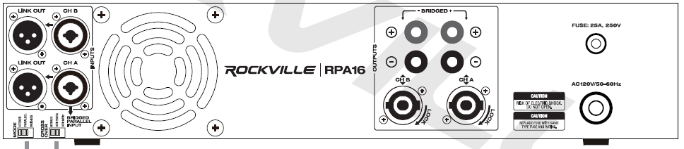
- Channel A /B XLR Link Out
- Channel A /B XLR /¼˝ TRS/ TS combo inputs
- Channel B Binding Post/Banana Plug outputs
- Channel A /B Binding Post/Banana Plug bridged output
- Channel A Binding Post/Banana Plug outputs
- User serviceable fuse compartment (25A/250V)
- Mode switch: stereo/parallel/bridged
- Crossover switch: bypass/80Hz/160Hz
- Built-in automatic variable-speed high-velocity cooling fan
- Channel A /B Speakon outputs
- AC 120V/50 – 60Hz power input
SetupRack Mounting
The RPA16 was designed for standard 19˝ rack mounting and requires 2U rack space. Use the included heavy-duty rack mount ears, 4 screws, and 4 washers for mounting to the front rack rail. Preferably, the side wall should be at least 2˝ from the sides of the amplifier and the back of the rack should be open. This will ensure a source of cool air to all sides. Be sure to support the rear of the amp, especially for mobile use where it will be subjected to strong vibrations. The RPA16 can also be “stack” mounted without a cabinet.
ConfigurationsCrossover and Mode Switches
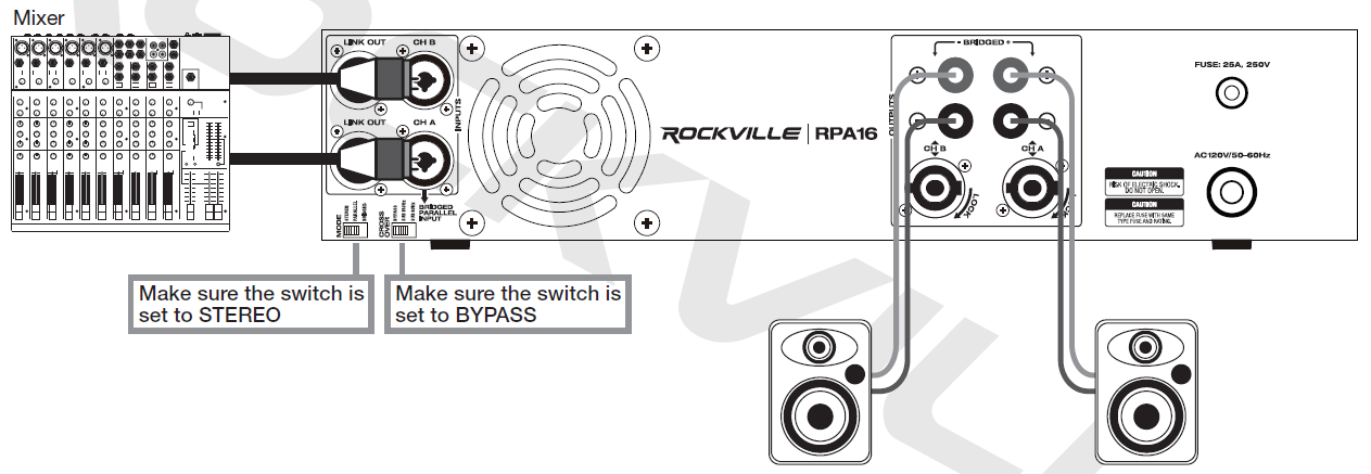
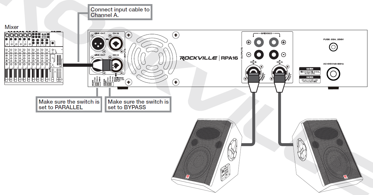
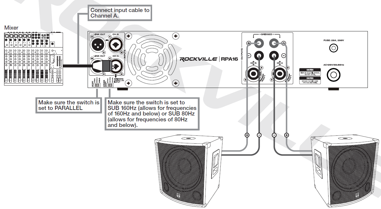
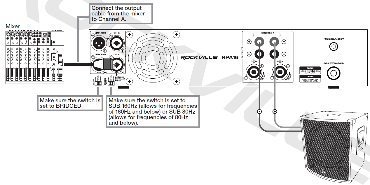
In STEREO mode the amplifier is fed a full-range signal and outputs a specific left and right signal. Each channel is fully independent and has a separate level control. Make sure the speakers’ impedance is no less than 4 ohms.In PARALLEL mode the channels are connected internally. On the RPA16 Channel A is the dedicated input for use when in this mode. The signal input to Channel A will feed a mono signal to both channels. Eachchannel has a separate level control.In BRIDGED mode, the amplfier operates as a one channel mono amp. The power from both channels is combined into one channel. As with parallel mode, the channels are connected internally and Channel A is the dedicated input. The signal input to Channel A will feed a mono signal to the positive binding post output terminals of each channel. The Channel B positive output is connected to the negative input of your speaker. The Channel A positive output is connected to the positive input of your speaker. This mode is primarily used when connecting subwoofers.
Set the switch to BYPASS when using full-range speakers.Set the switch to SUB 80Hz or SUB 160Hz when using subwoofer(s). This will allow frequencies below 80Hz or 160Hz only.
Stereo
Parallel (mono to speakers)
Parallel (mono to passive subwoofers)
Bridged (mono)
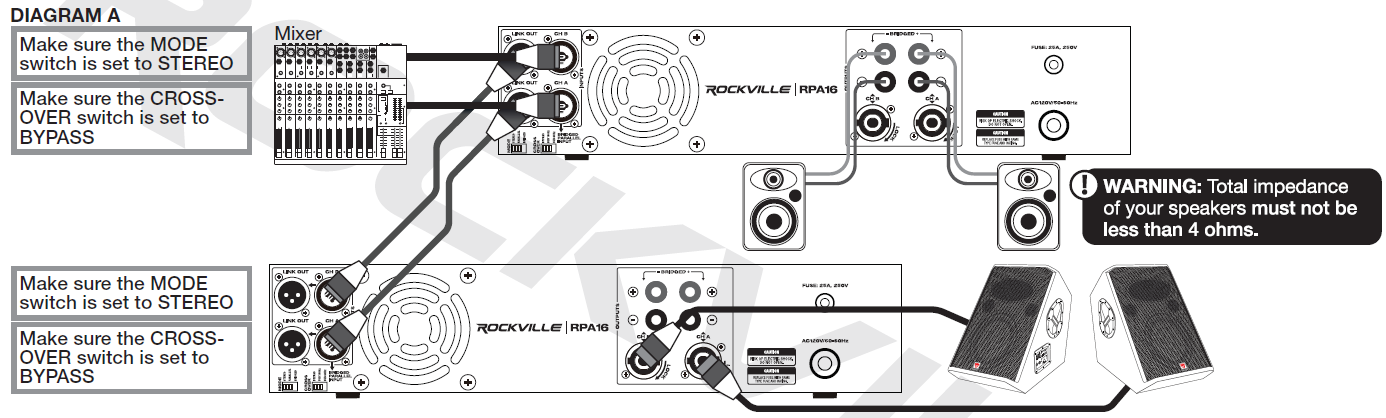
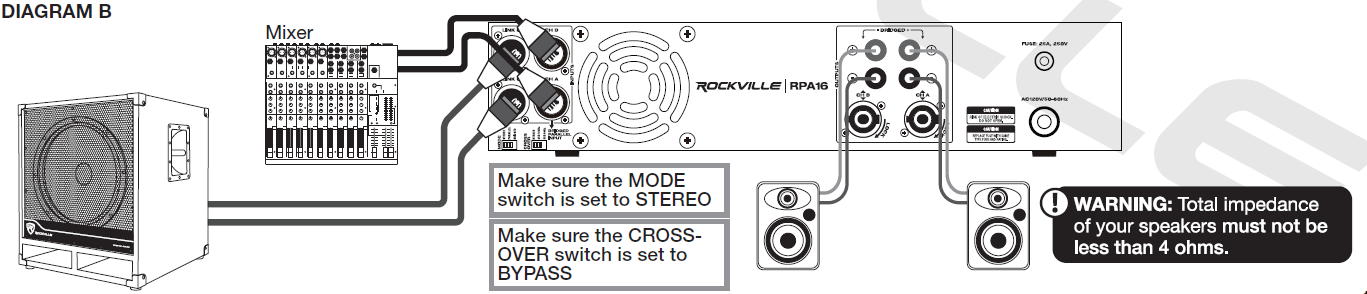
Link Out XLR
These set ups allow you to use the RPA16’s XLR Link Out ports to send the full range signal from the main amp to a secondary amp (diagram A) or directly to a powered sub (diagram B).
Features/Specifications
- LCD displays the volume in dB per channel and the operating temperature
- 2U rack space
- Built-in limiter protects your speakers from distortion and clipping
- Bridged mode allows you to combine both channels’ power into one channel for use with a subwoofer
- Stereo mode is perfect for (2) speakers or (4) speakers in a left and right configuration
- Parallel mode gives you dual mono output signals, which is perfect for monitor use when you want all sounds coming out of each speaker instead of a L/R configuration
- Built-in crossover switch (bypass, 80 Hz, 160 Hz) allows amp to be used with full-range PA speakers or Subwoofer(s)
- Channel A & B Clipping Led Indicators
- Channel A & B Separate Level Controls
- Power, signal, clipping, and protection LED indicators on front of amp
- Heavy-duty rack mount ears with handles
- Built-in variable-speed high-velocity quiet cooling fan
- Maximum headroom for 4-ohm and 8-ohm speakers
- Input Terminals: Combo jack (XLR and ¼˝) A & B inputs
- Output Terminals: Banana binding post speaker output, Speakon output, XLR output (to connect another amplifier or powered sub)
- Level controls for precise setting and matching of sensitivity
- Computer controlled IC protection circuitry against speaker short circuit, thermal over load, DC over load
- User serviceable fuse (25A, 250V)
- RMS Power Output: Stereo 8 Ohm: 2 x 1000WStereo 4 Ohm: 2 x 1500WBridged 8 Ohm: 1 x 3000W
- Peak Power Output: Stereo 4 Ohm: 2 x 5000W MaxBridged 8 Ohm: 1 x 10,000W Max
- Frequency Response (bandwidth @ 2Vrms out, @ -3.0dB) 10Hz – 30Khz|
- THD + Noise @ 1Khz full power: <0.04%
- Input Impedance: 10K Ohm Balanced
- Input signal voltage: 660mV – 1.5V
- Input sensitivity: 0.7v
- Damping factor: (100Hz, 10w, 4 ohms): 36.5
- Damping factor: (1KHz @ 8 ohms): >400:1
- Effective damping factor (100Hz, 10w, 4 ohms) 1.08
- Output impedance at speaker terminals: 0.10975 ohms
- Frequency Response vs THD+N (worst case, across normal bandwidth 1W) 0.6%
- Signal to Noise Ratio: >100dB
- IMD 60Hz & 1KHz, 4:1: <0.04%
- SLEW RATE (input filter limited): 40v/uS
- Power Requirements: 120V/50 – 60Hz
- Weight: 40.8 lbs
- Dimensions: 19.09 x 16.93 x 3.35 inch
Troubleshooting
| PROBLEM | SOLUTION |
| No power | 1. Make sure the unit is plugged in and the power switch is in the ON position.
2. Check that the power cable is properly plugged into the wall socket. 3. Check and replace the fuse if necessary. 4. If people or equipment tend to step on and roll over or stretch your power cable it can get damaged. Check the power cable for damage. If the cable is damaged, discontinue using the unit until the cable can be repaired. |
| No sound | 1. Check that all appropriate cables and wires are plugged in correctly.
2. Check the channel level settings. 3. Check the volume settings on your input devices. 4. Check mixer’s master and input volumes. 5. Make sure you are using the proper cables. 6. Make sure speakers are connected to the amp’s OUTPUT, not INPUT. 7. Make sure mixer is connected to the amp’s INPUT, not OUTPUT. 8. Make sure the mixer’s mute isn’t on. |
| Clipping light is on | 1. Turn down signal level controls (gain).
2. Check impedance of speakers or subs. |
![]()
References
[xyz-ips snippet=”download-snippet”]