ROCKVILLE BATTERY PAR 50 Owner’s Manual
Thank you for purchasing this Rockville BATTERY PAR 50 Rechargeable Battery Powered Wash Light. Please read this owner’s manual carefully for proper use of your Rockville BATTERY PAR 50. Should you need assistance please call our technical help line at 1-646-758-0144, Monday through Friday, 9am to 5pm EST.
Includes
- Par Light
- Remote control
- Dual bracket
- Adapter
- Owner’s manual
- Warranty card
IMPORTANT SAFETY INSTRUCTIONS
NO USER SERVICEABLE PARTS INSIDE. WE RECOMMEND TAKING THE UNIT TO A QUALIFIED SERVICE TECHNICIAN FOR ANY REPAIRS.
- To reduce risk of electric shock, never open the unit. There are no user serviceable parts, refer service to an authorized Rockville service center.
- Avoid looking directly into the lights.
- Do not expose this unit to any kind of moisture.
- The products housing may become hot during operation. Do not touch.
- This device has an IP20 rating and is intended for indoor use only.
- Do not operate this unit when the cover is open.
- Do not attempt to operate this unit if the power cord has been frayed or broken.
- Do not attempt to break off or remove the ground prong. This prong is used to reduce the risk of electrical shock and fire in case of an internal short.
- Never plug this unit into a dimmer pack.
- Do not operate this unit if it is damaged.
- This unit is intended for indoor use only.
- During long periods of non-use, disconnect the unit from power source.
- Always mount this unit in a safe and stable matter.
- Power supply cords should be routed so that they are not likely to be walked on or pinched by items placed upon or against them, paying particular attention to the point of exit from the unit.
- To avoid unnecessary wear and to improve the unit’s lifespan, unplug the unit when not in use for extended periods of time.
- Assembly and installation of the device must be carried out by a specialist familiar with the hazards and the relevant regulations. Maintenance, operation and commissioning of this device must only be carried out by qualified persons. • When choosing a location for your device, make sure to avoid impact, vibration, dust, hot and cold temperatures and dampness. Furthermore, no powerful transformers or motors must be used close to the device.
- The effect light must only be operated at a maximum ambient temperature of 40 °C.
- Never cover the device. Make sure when mounting with other equipment that there is sufficient ventilation. Maintain a sufficient distance to other devices and walls. Never in stall the effect light in direct proximity of heat sources. Do not point any strong spot lights or light sources towards the device. This may cause overheating (danger of fire!).
- Do not drill or screw additional screws into the casing in order to fasten the device. This may expose dangerous voltage to touch.
- The device must be mounted out of normal reach.
- Illuminated objects must be at least 0.5 m away from the device’s light emission source. Easily flammable materials such as decorative fabrics must also have a distance of at least 0.5 m to the device. Otherwise, such objects may catch fire!
- When mounting the product, make sure that the power cord is neither jammed nor damaged by sharp edges.
- During installation or service work, the area below the place of installation must be cordoned off.
- The installation surface or mounting fixture needs to be designed in a way that it can take 10 times its load capacity for at least 1 hour without permanent damaging deformation.
- It is also essential that the device is secured by means of a second safety restraint that is independent of the actual mounting supports when installing it in an elevated position. No part of the installation must fall down if the main suspension system fails.
- Observe all relevant regulations of your country when installing the device. Acceptance test (in case of industriaVpublic use):
- Before first use and after any significant modifications, the installation (including the electrical connections) must be inspected by an official expert.
- A yearly inspection by an expert is required.
- At least every 4 years, an acceptance test must be carried out by an expert.
- If you want to mount the device on a suitable traverse system, attach the effect light with the mounting bracket and a suitable traverse clamp that is available separately.
- For this, install the effect light with the assembly bore of the mounting bracket to the traverse clamp and that in turn to the traverse system. Use only assembly material suitable for the type of assembly and for bearing the effect light load.
- The assembly must never swing vfreely.
- Additionally secure the installation with a suitable safety restraint cable or a safety net.
- The safety retention rope or the net must be designed to support the effect light in the event of failure of the main support system independently of the main attachment.
Maintenance and Cleaning
Always observe the following safety instructions before cleaning or servicing the effect light:
- Live components may be exposed if covers are opened or components are removed.
- The device must be disconnected from all power sources before any servicing or repair work is carried out.
- Capacitors inside the device may still carry voltage even though they have been discon-nected from all power sources.
- Only qualified experts familiar with the hazards involved and the relevant regulations must perform repairs.
- Never use any aggressive cleaning agents, cleaning alcohol or other chemical solutions, since these may damage the casing or even impair function.
- Always disconnect the product from the power supply before cleaning it.
- Use a dry, lint-free cloth for cleaning the product.
Functions
- Power LED indicator
- DMX in
- Rubber feet
- LCD display
- DMX out
- Battery level LED indicators
- Power linking socket (power out)
- Power button
- IEC AC power socket w/user serviceable fuse compartment
- Controls:
- Mode – Press repeatedly to see mode options.
- Up – Scroll up through settings.
- Down – Scroll down through settings.
- Enter – Use to make selection.
Remote
- Dim brightness/adjust speed
- Static color: Red, Green, Blue, White
- Preset static colors 4. Power off/on
- Color change mode 6. Strobe mode
- Fade mode (gradual change)
- Sound mode
Charging
To charge the BATTERY PAR 50 plug the charger into any 110v wall socket, plug the other end to the unit’s power input socket, and turn off the power. Charge the battery for at 4 hours to attain a full charge. After a full charge, the battery can last 8 hours with all LEDs on or up to 11 hours with one color on. Results will vary based on LED brightness.
PLEASE NOTE: The fixture must be charged for 6 – 7 hours when charging for the first time.
Operation
Use the MODE button to enter the settings menu. Use the UP and DOWN buttons to select the desired setting and set their values. Press and hold the UP and DOWN buttons to scroll quickly through the menu options. Press the ENTER button to save your selection. Press MODE to exit.
|
DisplayMode |
Value |
Description |
|
|
 |
3 Channel DMX mode |
 |
6 Channel DMX mode |
|
|
|
 |
Infrared remote sensor on/off |
|
Color change |
||
|
|
 |
Seven color fade |
|
|
|
Single color fade |
|
Sound activated mode |
||
|
|
|
Red dimmer |
|
Green dimmer |
||
|
|
Blue dimmer | |
 |
Strobe mode |
Master/Slave Mode
- Connect to power source and turn on all fixtures.
- Connect all fixtures via the DMX IN/DMX OUT ports.
- Set all fixtures to DMX mode A001 (3CH) or d001 (6CH) on the panel display.
- Select one fixture to be the master. All other fixtures will follow the master fixture.
DMX Mode
The BATTERY PAR 50 can be controlled via any DMX Controller. From your DMX controller you can change the color, control different modes, create scenes, and program chases. You can also daisy chain multiple BATTERY PAR 50 units together via DMX cables. The Fixture uses either 3 or 6 channels depending what DMX mode you are in.
DMX Channels
To set the DMX starting channel address press the MODE button until you see A001 (3-channel mode) or d001 (6-channel mode). Now use the UP and DOWN buttons to set the DMX address of the light. If you are using this light with a DMX controller be sure to set each light fixture 16 channels apart to get independent control of each fixture. For example if you had two lights you would set the first light to DMX channel A001 (or d001) and the second light to A017 (or d017), and so on and so forth. Press the ENTER button to save your selection.
DMX Termination (Optional)
The last fixture of a DMX chain has to be “terminated”. This prevents electrical noise from disturbing and corrupting the DMX control signals. To terminate the last fixture solder a 1/4 Watt, 120 Ohm resistor across the DATA – and DATA + wires. The connections are illustrated below. If you are only connecting a few fixtures which are close together and use a short run to the controller, you may be able to operate without a terminator. Please see the dia-gram below.
DMX Termination Diagram
DMX Controller Function
When using a DMX controller,use the chart below to reference each channel’s function.
3-Channel Mode
| Ch. | Function | Value | Description |
| 1 | Red | 0 – 255 | Adjust individual LED brightness |
| 2 | Green | 0 – 255 | |
| 3 | Blue | 0 – 255 |
6-Channel Mode
| Ch. | Function | Value | Description |
| 1 | Master Dimmer | 0 – 39 | Adjust all LED brightness |
| 2 | Red | 40 – 59 | |
| 3 | Green | 60 – 79 | Adjust individual LED brightness |
| 4 | Blue | 80 – 99 | Function settings |
| 5 | DMX control | 0 – 50 | |
| Color change | 51 – 100 | ||
| Color fade | 151 – 200 | ||
| Strobe | 201 – 255 | ||
| Sound activated mode | 0 – 255 | ||
| 6 | Speed | 0 – 255 | Adjust speed for Ch.5 or adjust strobespeed for Ch. 2 – 4 |
Installation
Floor InstallationThis unit features dual brackets for easy floor installation. Simply loosen the locking knobs on the sides of the light (fig. a), spread the legs apart (fig. b), set the light angle (fig. c), and tighten the locking knobs to secure the desired position (fig. d). Alternatively, you can set the light down on its rubber feet (fig. e).
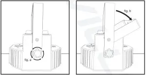
Truss InstallationTo hang the fixture from a truss, use any standard mounting clamp (not included). There is a mounting hole located on the top of each bracket (fig a). Secure the mounting clamp and bracket to these mounting holes (fig. b). Be sure to use a suit-able safety restraint cable.
Features and Specifications
- • Built in 3200mAh lithium rechargeable battery
- Battery lasts 11 hours with a single color and 8 hours with all colors
- Charging time: 4 hours (minimum)
- Battery overcharge protection
- Light source: (6x Red, 6x Green, 6x Blue LEDs)
- 18 LEDs/1W each • DMX controls: 3 or 6 channels
- Linkable in master/slave mode using 3-Pin DMX cable
- 3 Pin XLR DMX input & output
- Remote control included
- 1,102 Lux @ 2m (All LED’s on)
- LED display to navigate settings
- Can be operated through the remote, through DMX, or you can use the built in programs or the built in sound activated mode
- Automatic modes: Static color, strobe, dimmer, gradient, and sound activated
- Beam angle: 25°
- Battery will still perform optimally even after hundreds of charging cycles
- DC 12V Charging input (via the included charger)
- Fan cooled
- Double bracket allows for multiple rigging or floor standing applications
- Voltage: AC110/240V – 50/60Hz
- Power consumption: 30W
- 16.7 millions colors
- 1 year warranty
- Black housing
- Create customized colors using the built-in LCD display
- Replaceable batteries
- 110/220V switchable for use in any country
- Dimmer: 0 -100% linear dimming
- Unit dimensions: 7″ x x 3.94″
- Unit weight: 1.87 lbs
Troubleshooting
| PROBLEM | SOLUTION |
| No Power |
|
| No power (battery mode) |
|
| No fixture DMX response |
|
| Intermittent DMX problems |
|
| Unit does not respond tosound |
|
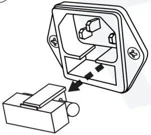
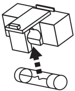
Fuse Replacement
- Use a screwdriver to release the fuse holder

- Remove the fuse holder
- Remove the fuse
- Replace the fuse
- Re-insert the fuse holder

 report this ad
[xyz-ips snippet=”download-snippet”]