![]() OWNER’S MANUAL
OWNER’S MANUAL
DMX-CT (Transmitter)DMX-QR (Receiver)2.4GHZ WIRELESS DJ DMX LIGHTING TRANSMITTER or RECEIVER w/1.25 MILE RANGE
Please read this owner’s manual carefully for proper use of your DMXCT or DMX-QR wireless DMX modules. Should you need technical assistance please call our technical helpline at 1-646-758-0144, Monday through Friday, 9 am to 5 pm EST.
IMPORTANT SAFETY INSTRUCTIONS

NO USER-SERVICEABLE PARTS INSIDE. WE RECOMMEND TAKING THE UNIT TO A QUALIFIED SERVICE TECHNICIAN FOR ANY REPAIRS.
- For indoor use only. Do not expose units to moisture.
- Only use the included power adapters. Do not use the adapters if the cord is damaged in any way. Do not break off the ground prong as this increases the risk of electric shock.
- The working temperature range is – 4° – 113° F (-20° – 45° C), 10% – 90% relative humidity.
- Make sure there are no obstructions between the transmitter and the receiver(s).
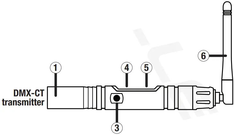
Functions
- XLR 3 pin male connector
- XLR 3 pin female connector
- 5-volt power input
- ID display
- ID key
- Antenna
Operation
- Power up the DMX-CT and/or DMX-QR by connecting the power supply.
- Connect the DMX-CT to the DMX source.
- Connect the DMX-QR(s) to the desired fixture(s).
- Press the ID key on the DMX-CT to indicate the ID setting. Press again to set the ID. To change the ID value, press the key button until the desired value is found. To set the ID for the DMX-QR, follow the procedure above. Please note that the ID needs to match on both the DMX-CT and DMX-QR. If your fixture has a built-in transmitter and you are only using a DMX-QR unit, its ID shouldmatch the fixture’s ID. When the units are used in the future, they will remember the previously used ID.
- The DMX-CT will automatically look for and choose an interference-free channel which it will also assign to the DMX-QR. If there is over 10%interference, the DMX-CT will switch to another channel and set the DMX-QR to that same channel. If the whole frequency is occupied, the DMX-CT will switch to frequency hopping mode.
- Once communication is established, the DMX-CT ID value light will be on and the number on the ID display will flash. The DMX-QR ID value light will be off and the number on the ID display will also flash.
Pairing the DMX-QR Transmitter to a DMX-WTR ReceiverThe DMX-WTR uses a color-coded system for syncing and the DMX-QR uses a number ID system. Follow the steps below to sync the transmitter to the receiver.
- Power up the DMX-WRT unit by connecting the power supply and pressing the Power button once.
- Now power up the DMX-QR unit by connecting the power supply.Operation (continued)
- Connect the DMX-WTR to the DMX source.
- Connect the DMX-QR unit to the desired fixture.
- Press the ID key on the DMX-WTR to indicate the ID setting. Press again to set the ID color. To change the ID color, press the keybutton until the desired color is found.
- Press the ID key on the DMX-QR to indicate the ID setting. Press again to set the ID value. To change the ID value, press the keybutton until the desired value is found.
DMX-WTR ID Color and Corresponding DMX-QR ID Value:
- RED = ID 1
- GREEN = ID 2
- YELLOW = ID 3
- BLUE = ID 4
- PURPLE = ID 5
- TURQUOISE = ID 6
- WHITE = ID 7
Please note: The DMX-WTR has 7 ID channels and the DMX-QR has 16 ID channels. Only the first 7 channels on the DMX-QR are used. If you go past the 7th channel, your DMX-QR will cease communicating with the DMX-WTR. In order to reestablish communication, you must cycle through the additional 9 channels until you reach channel 1.Go to vimeo.com/461140940 or scan the QR code to watch a short video with additional information on pairing the DMX-WTR to the DMX-QR.

Features and Specifications
- Transmitter and receiver are universal – they work with any brand l lights that have DMX controls.
- Distance: 1.25-mile range (2,000 meters)
- ID code is adjustable with 16 ID groups: 0 – 9, A – F
- Users can have 16 different groups of lights independently adjustable without any interference.
- Easily link multiple receivers to the transmitter with the digital display.
- Supports 512 DMX channels
- You can daisy chain multiple lights together and use one receiver for all the lights that are linked together. This setup requires onetransmitter and one receiver.
- You can connect one transmitter to your DMX controller and then one receiver to each group of lights, and then each group will have its own channels on the controller so they can all be controlled independently.
- Real-time responsiveness with zero delays and 100% reliability.
- Efficient GFSK modulation with 126 channel high-speed frequency hopping (FHSS) for interference-free operation.
- Makes it easy to set up all your lights without a ton of wires everywhere.
- Max transmitting power rate: 19.5dB
- Receiver sensitivity: -102dB
- DMX signal port: 3-Pin
Applications
- Stage lighting
- Uplighting (wall washing)
- DJ lighting
- Clubs/Bars
- Party halls
- Theatrical performances
- Stadium lights
Troubleshooting
| PROBLEM | SOLUTION |
| No power | 1. Make sure the power adapter is properly plugged in at the wall and to the unit.2. Make sure the power adapter is not damaged. |
| Units not responding toDMX | 1. Check that the DMX-CT and DMX-QR(s) are powered on.2. Check that the ID key on the receiver or transmitter matches.3. Check that the transmitter is connected to the DMX OUT port of the controller and that the receiver is connected to the DMX IN port of the fixture. |
FEDERAL COMMUNICATIONS COMMISSION COMPLIANCE INFORMATIONResponsible party name: Rockville
Address: 600 Bayview Ave.Entrance AInwood, NY 11096
Hereby declares that the products DMX-CT Transmitter and DMX-QR Receiver comply withFCC rules as mentioned in the following paragraph:This device complies with Part 15 of the FCC rules. Operation is subject to the following two conditions: (1) this device may not cause harmful interference, and (2) this device must accept any interference received, including interference that may cause undesired operation.Note: This equipment has been tested and found to comply with the limits for a Class B digital device, pursuant to Part 15 of the FCC rules. These limits are designed to provide reasonable protection against harmful interference in a residential installation. This equipment generates, uses, and can radiate radio frequency energy and, if not installed and used in accordance with the instructions, may cause harmful interference to radio communications. However, there is no guarantee that interference will not occur in a particular installation. If this equipment does cause harmful interference to radio or television reception, which can be determined by turning the equipment off and on, the user is encouraged to try to correct the interference by one or more of the following measures:
- Reorient or relocate the receiving antenna.
- Increase the separation between the equipment and receiver.
- Connect the equipment to an outlet on a circuit different from that to which the receiver is connected.
- Consult the dealer or an experienced radio/TV technician for help.
 report this ad
![]()
RockvilleAudio.com© 2020 ROCKVILLE // Features and specifications are subjectto change and or improvement without notice.
References
[xyz-ips snippet=”download-snippet”]