![]()

![]()
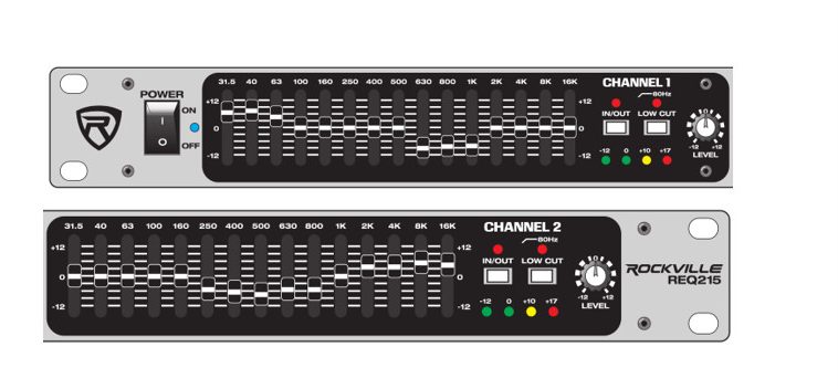
Thank you for purchasing this Rockville REQ215 Dual Channel 30 bank Rack Mountable EQ. Please read this owner’s manual carefully for proper use of your Rockville REQ215. Should you need technical assistance, please call our technical helpline at 1-646-758-0144, Monday through Friday, 9 am to 5 pm EST.
IMPORTANT SAFETY INSTRUCTIONS
- To reduce risk of electric shock, never open the unit. There are no user serviceable part, refer service to an authorized Rockville service center.
- Do not expose this unit to any kind of moisture.
- Please ensure that the unit is situated in a properly ventilated area.
- Make sure the unit is placed on a level on a level and stable surface.
Features/Specifications
- Dual-channel (15 bands per channel)
- 80Hz 24dB/Octave
- 2/3 octave filter sets
- 31.5Hz to 16kHz effective equalization range
- Constant Q filters
- Output level LEDs (-12 to +17dB)
- Low cut filter switch with status LED
- XLR inputs and outputs for balanced operation
- Bypass switch with status LED
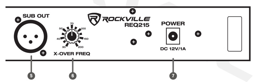
- Subwoofer out
- Subwoofer X-Over Freq (30Hz — 200Hz)
- Connectors: balanced XLR & TRS inputs and outputs
- Frequency Centers: 31.5Hz, 40Hz, 63Hz,100Hz,160Hz, 250Hz, 400Hz, 500Hz, 630Hz, 800Hz,1KHz, 2KHz, 4KHz, 8KHz,16KHz
- Input Impedance: 20k ohms
- Output Impedance: 1.5k ohms
- Maximum Output Level: 11 VAC
- Level Control: +/- 12dB
- Signal to Noise: 90dB
- Distortion: 0.03%
- 100-240V worldwide voltage power adaptor
Functions
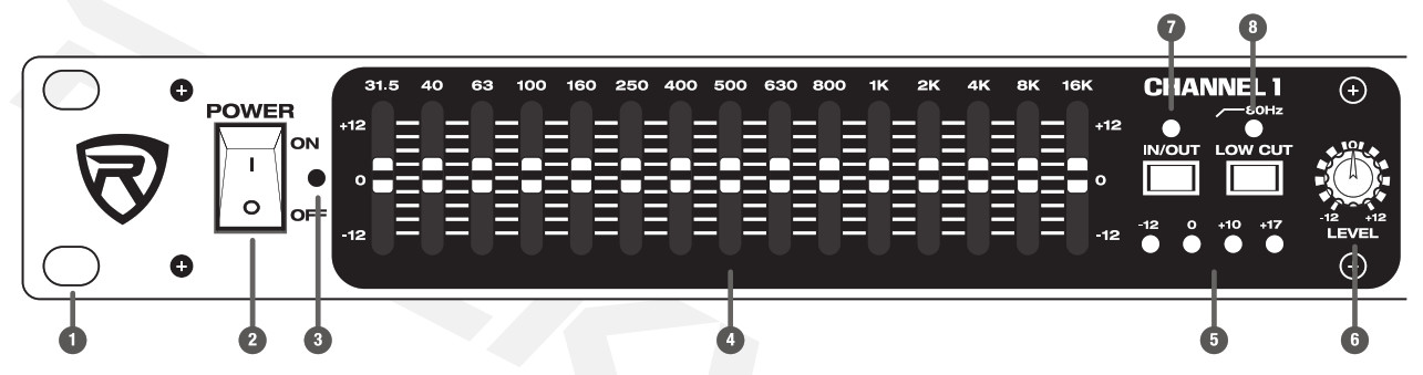
- Rack ears: allows for unit rack mount using four attaching screws and washers (not included).
- Power switch
- Power-on LED indicator
- Equalization sliders: cut or boost corresponding frequencies by ±12dB.
- Level meter LEDs: indicate the input/output levels from -12dB – +17dB.
- Level control: The level control can attenuate or boost the signal by up to 12dB. 0dB is normalized at 12 o’clock. Turn the knob counter-clockwise for up to 12dB of attenutation or clockwise for up to 12dB of gain.
- Bypass switch: engage this switch and the input signal will bypass all features except the LOW-CUT FILTER (see item 8). The signal is routed from INPUT though the low-cut filter to the channel’s output. Bypass is indicated by the LED located above the switch.
- Low-Cut Filter switch: use this switch to activate the low-cut filter which will attenuate frequencies below 80Hz. Frequency roll-off is 24dB per octave. Low-cut filter is indicated by the LED located above the switch.
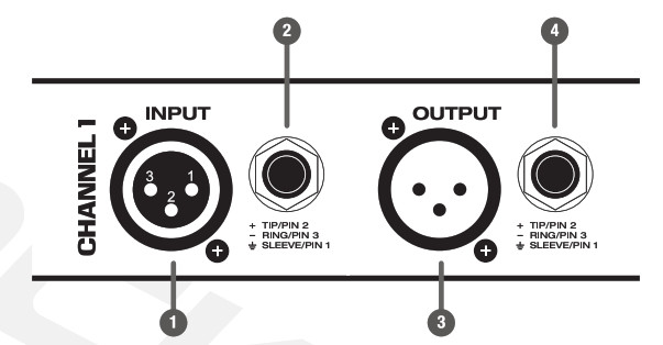
- Balanced XLR input
- Balanced 1/4″ TRS input
- Balanced XLR output
- Balanced 1/4″ RTS input

- XLR Passive subwoofer output
- Crossover Frequency control: 30Hz-200Hz
- DC 12V power input

RockvilleAudio.com©2020 ROCKVILLE/Features and specifications are subject to change and or improvement without notice.
[xyz-ips snippet=”download-snippet”]