
High Performance Wireless Microphone System

Thank you for purchasing this Rockville RWM1203VS. Please read this installation guide carefully for proper use of your Wireless Microphone System. Should you need assistance please call our technical help line at 1-646-758-0144, Monday through Thursday, 9am to 10pm EST, and Fridays, 9am to 3pm.
FEATURES
- High performance wireless microphone system
- Includes transmitter with two headset microphones
- High sensitivity, unidirectional, wireless cardioid microphones
- Featuring a dual filter design to limit feedback and interference
- Transmitter automatically links to receiver for ease of use
- Durable composite microphone construction
- Comfortable ergonomic design
SPECIFICATIONS SYSTEM
Operating Range: 100′ -200′(indoor), 65′ -165′(outdoor) Audio Frequency Response: 80-12000Hz Dynamic Range: 2!:80dB Signal-to-Noise Ratio: 2!:80dB Operating Temperature: 41 °F-113°F Carrier Frequency Range: 180-280MHz
RECEIVER
Sensitivity: (S/N=30d8) >2mV De-Emphasis: 50μS Audio Output Impedance: 6000 Audio Output Level.: 0-0.5V Power Supply: AC11 0V /50HzCurrent Consumption: s50mA Audio Out Connector: 1 /4″ unbalanced
TRANSMITTER
Frequency Stability: ±0.005% RF Output Power: s30mW Modulation Mode: VHF Maximum Deviation Range: ±50KHz Microphone Mode: FixedPre-Emphasis: 50μS Power Supply: 9V Batt./1.5Vx2 Current Consumption: s35mA
*Operating range is subject to environmental conditions. Results may vary.
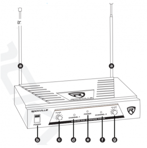
Receiver (Front)
a. Antennab. Power on/off switchc. Channel 1 Volume adjustment knobd. Channel 1 LED indicatorr;;ie. LED power indicator IIf. Channel 2 Volume adjustment knobg. Channel 2 LED indicator
a. Antennas 9b. Audio out (1/4″ TRS connection)c. Power plug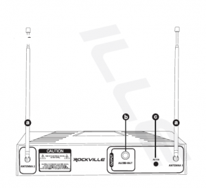
a. Microphone windscreenb. Power on/off switchc. Connector jack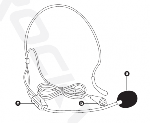
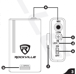
Body pack
a. Microphone inputb. Battery compartmentc. Gain controld. LED power indicator When ON the LED power indicator will be on. When the unit reaches 10% power or less, the LED will begin to flicker until it turns offe. ON/OFF switch When the switch is in the middleposition, the microphone will be on MUTE/ STANDBYf. Belt clip
Setup and Operation
For best performance of the wireless microphone system you should make sure that you run the cable from the receiver output to a Microphone input on a poweredspeaker or mixing board. If you run it right into a line level input then the audio\ volume level output of the microphone(s) will drop significantly. Most mixers andpowered speakers have both a Microphone input and a line level input.
- The receiver should be placed in an area that is stable and least likely to shake the unit.
- The receiver should be at least 3· off the ground for optimal transmission.
- Connect the antenna, balanced cable AF line, and power supply provided.
- The antenna should extend vertically.
- Switch on the receiver.
- While the receiver is in stand-by, switch on the microphones.
- Adjust volume as necessary.
- Use trim adjustment on the body pack to fine tune the mic gain so that the audio output is louder (MAX) or softer (MIN).
- When you power ON the body pack, the LED indicator will flicker and turn off. Upon requiring a battery replacement the LED indicator will remain on
Troubleshooting
Problem |
Solution |
| No sound or faintsound |
|
|
|
|
|
| Audio artifacts ordropouts |
|
| Distortion | Reduce transmitter channel volume. |
| Sound level variations when switching to different sources | Adjust transmitter volume as necessary. |
| Transmitter information does not appear on the Receiver LCD | Transmitter is off. |
Visit us at:
RockvilleAudio.com
Read More About This Manual & Download PDF:
[xyz-ips snippet=”download-snippet”]