
ROCKVILLE RPM109 12 channel 4800W Powered Mixer Owner’s Manual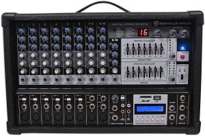
Thank you for purchasing this Rockville RPM109 12 Channel Powered Mixer. Please read this installation guide carefully for proper use of your RPM109. Should you need assistance, please call our technical help line at 1-646-758-0144, Monday through Thursday, 9am to 10pm EST., and Fridays, 9am to 3pm EST.
![]() IMPORTANT SAFETY INSTRUCTIONS
IMPORTANT SAFETY INSTRUCTIONS
- To reduce risk of electric shock, never open the unit. There are no user serviceable parts, refer service to an authorized Rockville service center
- Do not expose this unit to any kind of moisture
- Please ensure that the unit is situated in a properly ventilated area
- Make sure the unit is placed on a level and stable surface
Function
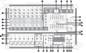
- . Input Equalizer control: 3-band equalizer that adjusts high, mid, and low frequencies.High: 12KHz ±15dBMid: 2.5KHz ±15dBBass: 80Hz ±15dB
- Monitor control: controls the amount of signal sent to the MONITOR bus.
- Effect control: controls the amount of signal sent to the EFFECT bus.
- Pan control: determines the position of the channel signal within the stereo image. It features a constant-power characteristic, which means the signal is always maintained at a constant level, irrespective of position in the stereo panorama.
- Level control: controls the volume and adjusts the output level.
- Clip LED: indicates that the input signal is too high.
- PAD switch (Ch1 – Ch6): attenuates the input signal by 20dB. Use this feature when connecting a line level device or if the Mic input is distorted.
- Line/High impedance ¼˝ balanced (TRS) inputs (Ch1 – Ch6): This input may be used as either a high-impedance microphone input or for line-level devices such as a cassette player, CD player, video projector or laptop. Will also allow connection from an electric guitar, bass or keyboard. It is a two-conductor input with an impedance of 10K ohms.
- Microphone/Low impedance XLR input: connect balanced low impedance microphones with an input impedance of 1K ohms.PIN 1 = shield, PIN 2 = positive (hot), PIN 3 = negative (cold)
- Stereo Channel input (Ch7/8 & Ch9/10): These are stereo inputs featuring a balanced XLR input and L/R ¼˝ unbalanced (TS) inputs.When the Left ¼˝ jack is used alone, the signal input is mono.
- Channel 11/12: These controls are used to adjust the signal from the CD/TAPE line level inputs or the MP3 player input. To switch between the two, use the CD TAPE/MP3 switch (see item 16).
- Aux in: controls volume of Aux line input as well as MP3 input (USB/SD).
- Aux input (Ch11/12): These are stereo inputs for connecting MP3 player or any other line level input. It features L /R ¼˝ balanced (TRS) inputs as well as L/R RCA mono inputs. When the Left ¼˝ jack is used alone, the input signal is mono.
- Rec output: L/R RCA output to Tape or CD recorder (–10dB output level).
- CD TAPE/MP3 button: switches Ch11/12 input signal between MP3 (USB/SD) and line level inputs.
- Digital Stereo Effects display: shows the current digital effect.
- Program control: this control allows you to select anyone of the 16 preprogrammed Digital Stereo Effects. These effects are designed to be added to dry signals. If you move the FX to MAIN control, you mix the channel signal (dry) and the effects signal. This also goes for mixing the effects signals with the monitor mix. The main difference is that the mix ratio is adjusted using the FX to MON control.
- Monitor control: controls the effectiveness of the digital effects monitoring channel.
- Main control: controls the effectiveness of the digital effects main channel.
- USB/SD/BT digital controller: Play/Pause, Stop, Repeat, Rewind, Fast Forward. LCD screen alternates (every 3 seconds) between displaying track playing time and total time.
- Mode control: Push to switch between modes (USB/SD/Bluetooth/FM Radio)
- Foot Switch input: connect a foot switch via this 1/4″ jack to BYPASS or ENGAGE the built-in effects.
- FX out: sends a stereo line level signal to an external effects processor. This signal can be RETURNED on any other LINE INPUT on the RPM109.
- Line Out: the L/R ¼˝ provide unbalanced (TS) output. The ¼˝ MON jack provides and unbalanced (TS) output signal.WARNING: Never use balanced and unbalanced connections simultaneously
- Power-on LED: indicates unit power status.
- Phantom Power switch and LED indicator: switch on phantom power when connecting condenser mics to Ch1 – Ch10.
- Master Monitor level control and LED meter: controls the monitor level, while the LED meter displays the level of the signal being sent from the Monitor (MON) jack (see item 24).
- Monitor graphic equalizer: 7 band EQ allows you to adjust the frequency response (±12dB) of the Monitor bus signal.
- Main Control and LED meter: controls the level of the Main bus. The LED meter displays the level of the signal being sent from the L/R¼˝ Main outputs.
- Main graphic equalizer: 7 band eq allows you to adjust the frequency response (±12dB) of the Main bus signal.
- SD/USB inputs. Please note: The RPM109 will not recognize USB drives formatted in the NTFS format; only the FAT or FAT32 formats.
- Power Amplifier control: LEDs indicate Monitor or Mains mode.Bridge/Main: sends the main mix to mains via Bridged Output on the rear panel. Please note that in this mode the monitors are disabled.Main/Main: sends the main mix to mains only via Speaker Outputs on the rear panel.Main/Monitor: sends the main mix to mains via Speaker Outputs on the rear panel and the monitor mix to monitors via Monitor Outputs on the front panel.
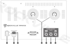
- Power switch
- IEC AC Power socket
- User serviceable fuse
- Dual vent fan cooling system
- Monitor output: speakON jack with an impedance of 4 ohms. Also serves as Right channel output when in MAIN mode.38. Bridgedoutput: speakON jack with an impedance of 8 ohms.
- Monitor output: speakON jack with an impedance of 4 ohms. Also serves as Left channel output when in MAIN mode.WARNING: Do not operate below rated minimum impedance.
Operation
Bluetooth Pairing and Operation
- . Press the MODE button until you see “bt” flashing on the display. The unit will automatically enter into pairing mode.
- Ensure that your device is in Bluetooth mode and discoverable.
- Find “ROCKVILLE” on your device’s list of available Bluetooth connections and select it.
- Once successfully paired, the word “bt” will stop flashing and remain solid.
- You can control playback from your device or you can use the MP3 controls.
Please note: input from the USB port will override Bluetooth input.
USB/SD OperationInserting a USB flash drive or an SD card into the corresponding port/slot will set the RPM109 to USB/SD mode and it will automatically begin to play music. Please note: The RPM109 will not recognize USB drives formatted in the NTFS format. Drives must be formatted in the FAT or FAT32 formats. Recognized file formats are MP3, WAV, and WMA.
Music Playback
- Play button: quickly press to play/pause current track.
- Stop button: quickly press to stop current track.
- Next button: quickly press to go to next track. Press and hold to raise volume.
- Previous button: quickly press to go to previous track. Press and hold to lower volume.
- Folder Selection (USB/SD only)
- Play button: quickly press to play songs in the selected folder.
- Stop button: press for 5 seconds to select desired folder.
- Next button: quickly press to go to next folder.
- Previous button: quickly press to go to previous folder.
Features/Specifications
- 12 Channel mixer section: 6 mono channels, 2 stereo channels, 1 dedicated USB/SD channel
- Built-in Bluetooth playback
- Studio-grade stereo FX processor with 16 presets including reverb, chorus, plate, delay, chorus, cathedral and various multi-effects
- 8 high-quality mic preamps with switchable +48V phantom power for condenser microphones
- 3-Band EQ (high, mid, low) per channel
- Pad Switch on each Mono Channel
- Clip LEDs on each Mono Channel
- Dual Stereo 7-band Graphic EQ allows for precise frequency correction of monitor and main outputs
- Selectable stereo (main L/R), double mono (main/monitor) or bridged mono amplifier operation mode
- Monitor Level Knob with 5 LED Level Meter
- Main Level Knob with 2 x 5 LED Level Meter
- Dual ¼˝ Stereo and Dual RCA Aux Input with Independent Level Knob for External Signal Sources
- Internal switch-mode power supply, noise-free audio, superior transient response and very low power consumption
- ¼˝ Foot-switch Input connector
- Dual RCA REC Out
- Dual ¼˝ Monitor Output
- Dual speakON jacks for Monitor Output
- Dual Fan vent Cooling System
- AC input: 120V
- RMS Power Output:
- 600w x 2 @ 4 Ohm
- 450w x 2 @ 8 Ohm
- 1200w x 1 @ 8 Ohm
- Program Power Output:
- 1200w x 2 @ 4 Ohm
- 900w x 2 @ 8 Ohm
- 2400w x 1 @ 8 Ohm
- Peak Power Output:
- 2400w x 2 @ 4 Ohm
- 1800w x 2 @ 8 Ohm
- 4800w x 1 @ 8 Ohm
Troubleshooting
| PROBLEM | SOLUTION |
| No power |
|
| No sound |
|
| Noise |
|
| Buzzing sound | Make sure you are using a proper cable. For ¼˝ cables, there are 3 types: instrument, TS (unbalanced), and TRS (balanced). Check the requirements of the connected gear and make sure you are using the appropriate cable. |
| Bluetooth pairing fails/no sound |
|
| No SD/USB
playback |
|
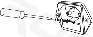
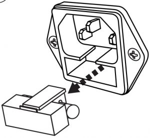
Fuse Replacement
- Use a screwdriver to release the fuse holder.

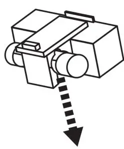
- Remove the fuse holder.
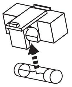
- Replace the fuse.
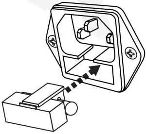
- Re-insert the fuse holder.
- Remove the fuse.
FEDERAL COMMUNICATIONS COMMISSION COMPLIANCE INFORMATIONResponsible party name: Rockville
Address: 600 Bayview Ave,Entrance A,Inwood, NY 11096
Hereby declares that the product RPM109 12 channel powered mixer complies with FCC rules as mentioned in the following paragraph:
This device complies with Part 15 of the FCC rules. Operation is subject to the following two conditions: (1) this device may not cause harmful interference, and (2) this device must accept any interference received, including interference that may cause undesired operation.
Note: This equipment has been tested and found to comply with the limits for a Class B digital device, pursuant to Part 15 of the FCC rules. These limits are designed to provide reasonable protection against harmful interference in a residential installation. This equipment generates, uses and can radiate radio frequency energy and, if not installed and used in accordance with the instructions, may cause harmful interference to radio communications. However, there is no guarantee that interference will not occur in a particular installation. If this equipment does cause harmful interference to radio or television reception, which can be determined by turning the equipment offand on, the user is encouraged to try to correct the interference by one or more of the following measures:
- Reorient or relocate the receiving antenna.
- Connect the equipment into an outlet on a circuit different from that to which the receiver is connected.
- Increase the separation between the equipment and receiver.
- Consult the dealer or an experienced radio/TV technician for help.
Web: RockvilleAudio.com

References
[xyz-ips snippet=”download-snippet”]