![]()
OWNER’S MANUAL
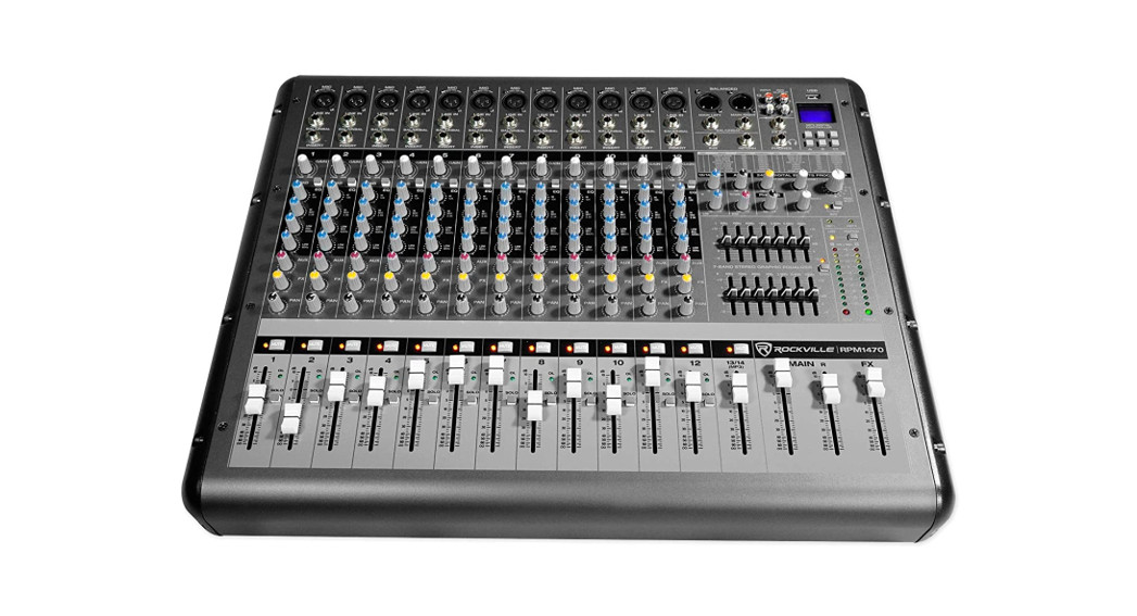
RPM1470 14CHANNEL 6000W POWERED MIXER w/BLUETOOTH, USB, 7 BAND EQ, and 24-BIT EFFECTS
Thank you for purchasing this Rockville RPM1470 14 Channel 6000W Powered Mixer with Bluetooth, USB, 7 Band EQ, and 24- Bit Effects. Please read this in- installation guide carefully for proper use of your Rockville RPM1470 14 channel mixer. Should you need assistance, please call our technical help line at 1-646- 758-0144, Monday through Friday, 9 am to 5 pm EST.
IMPORTANT SAFETY INSTRUCTIONS

- To reduce the risk of electric shock, never open the unit. There are no user-serviceable parts; refer service to an authorized Rockville service center.
- Do not expose this unit to any kind of moisture.
- Please ensure that the unit is situated in a properly ventilated area.
- Make sure the unit is placed on a level and stable surface.
- This unit can operate with either 110V or 220V.
Features/Specifications
- RMS Power Output:750w x 2 @ 4 Ohm500w x 2 @8 Ohm
- Program Power Output:1500w x 2 @ 4 Ohm1000w x 2 @ 8 Ohm
- Peak Power Output:3000w x 2 @4 Ohm 2000w x2
- 14 Channel mixer section: 12 mono channels, 1 stereo channel
- 12 high-quality XDR2 mic preamps with switchable +48V phantom power for condenser microphones.
- XDR2 mic preamps are low noise and low distortion. These are some of the best-sounding mic pre’s on the market. 1 dedicated USB input to playback music or record the main mix.
- USB supported formats are MP3, WAV, WMA.
- Bluetooth connectivity
- 24 BIT digital effects processor with 16 preset digital effects including (reverb, chorus, delay, chorus, phaser, flanger, and various multi-effects).
- Effects level control can adjust signal level of each effect.
- Effects mute button.
- FX footswitch input lets you turn your effects on or off. 4-Band EQ (high, high-mid, low-mid, low) per channel.
- Each channel is equipped with Pad, Mute, and Solo buttons with LED’s.
- Each channel has Gain, AUX control, FX control, Pan control, & Volume control.
- Red Peak LED indicates a signal level that is 5dB below clipping.
- Dual 7-band Graphic EQ allows for precise frequency correction of monitor and main outputs (with EQ kill switch).
- Aux send and Aux returns on every channel to connect all types of external effects and processors.
- You can control your monitor mix and check levels through your headphones.
- Limit L and Limit R LED indicators. These limiters are designed to go brighter as clipping gets stronger and will remain lit up until the channels stop clipping.
- We recommend lowering the gain if you see these LED’s lit up.
- Power and Output level LED indicators.
- Main output fader allows you to fade the sound between the left and right channels.
- RCA input, RCA output, and USB player.
- Headphone jack for monitoring the master signal and individually monitoring each channel with PFL, L/R.
- Gain control adjusts the sensitivity from -60dB to -20dB when the pad button is in the out position.
- When the pad button is pressed in the gain will adjust from 240dB to dB.
- Solo button allows you to hear the signals through your headphones or in the control room without having to route them to the main mix. This works even with the fader turned down. You can use this to preview channels before they are let into the mix or just to check out a channel during a live performance. You can solo as many channels at a time as you want.
- Built-in cooling fan and ventilation system.
- USB input supports unlimited capacity (as many GB as you want).
- 110/220V switchable power supply.
- Dimensions: (L*W*H) 22.44″ x 17.72″ x 7.09/57 x 45 x 18 cm
- Weight: 30.86Lbs. (14kg)
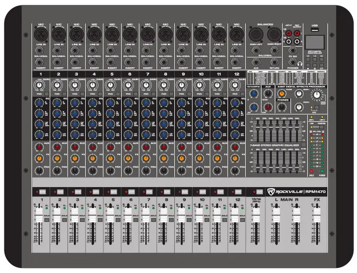
INPUT CHANNEL SECTION

- Balanced XLR Microphone Input
- Unbalanced 4″ Line Input
- Ya” Insert Output: The insert is a breakpoint in the input channel signal path. It allows the signal to be taken from the mixer, through an external device, and back to the mixer to continue to the final mix output.
- Gain Control: Adjust input sensitivity from -60dB to -20dB when the -20dB Pad button is depressed and -40dB to 0dBwhen the -20dB Pad button is pressed.
- Pad Button: Press to attenuate the input signal -20dB.
- Hi: Controls the high-frequency tone of each channel.Always set this control to the 12 o’clock position.
- Hi Mid/Lo Mid: Controls the mid-range frequency tone of each channel. Always set this control to the 12 o’clock position.
- Lo: Controls the low-frequency tone of each channel.Always set this control to the 12 o’clock position.
- Aux: Allows access to a portion of each channel’s signal which provides a monitor mix that can be fed to stage monitors, independent of the main mix. The control is off when fully turned down, delivers unity gain at the 12 o’clock position, and can provide up to 15dB of gain when turned up fully.
- FX: Allows access to a portion of each channel’s signal which provides an FX mix feeding the internal FX processor andexternal processors via the FX output. The control is off when fully turned down, delivers unity gain at the 12 o’clock position,and can provide up to 15dB of gain when turned up fully.
- Pan: The pan control sends continuously variable amounts of the post-fader signal to either the left or right main busses.In the center position, equal amounts of signals are sent to either bus.
- Mute: Pressing the Mute button will turn off the channel’s signal output.
- OL (Peak Level Indicator): The red LED indicates the signal level at the insert return point, premaster fader and illumi-nates at 5dB below clipping.
- Channel Fader: This slider adjusts the level of each channel into the signal mix. The U mark indicates unity gain, meaning noincrease or decrease of signal level.
- Solo: This switch allows you to hear signals through your headphones or control room without having to route them to the main mix. Use solo to preview channels before they are fed into the mix. You can solo as many channels at a time as you like.
MASTER SECTION

- Auxillary Return: This control sets the overall level of line signals received from the stereo (aux) return L/R jacks. Signals passing through this control go directly to the main mix and monitor mix where they are combined with signals from the channels.
- Auxillary Send: This control sets the overall level of the Aux to send prior to it going into the external effects device
- FX Send: This control determines how much of the effects processor’s signal should be added to the main mix.
- Phones: This knob controls the levels of the headphones and the main monitors.
- Digital Effects Processor: Features 16 effect presets with variable parameters. To select a specific effect, use the preset select knob. To control the parameters of that effect, use the knobs marked Param 1 and Param 2. To control how much of the effect is applied to the main mix, use the FX send knob (see item 18). The chart below shows the effects and the adjustable parameters. This chart is also printed on the mixer for your convenience.
PROG PRESET PARAMETER 1 PARAMETER 2 1 CHAMBER REVERB TIME DAMPING 2 PLATE REVERB TIME DAMPING 3 ROOM REVERB TIME DAMPING 4 CATHEDRAL REVERB TIME DAMPING 5 SPRING REVERB TIME DAMPING 6 GATED REVERB TIME DAMPING 7 REVERSE REVERB TIME DAMPING 8 DELAY + REVERB DELAY TIME REVERB TIME 9 BRIGHT DELAY TIME FEEDBACK 10 WARM DELAY TIME FEEDBACK 11 DARK DELAY TIME FEEDBACK 12 PING PONG DELAY TIME FEEDBACK 13 CHORUS RATE DEPTH 14 PHASER RATE DEPTH 15 FLANGER RATE DEPTH 16 ROTARY SPEAKER HIGH SPEED WIDTH - Hi: Controls the high-frequency tone of channel 13/14 (MP3). Always set this control to the 12 o’clock position.
- Low: Controls the low-frequency tone of each channel. Always set this control to the 12 o’clock position.
- Stereo Graphic Equalizer: Two 7-band graphic equalizers provide control! over frequencies ranging from 63Hz to 15KHz.
- EQ Kill Switch: This button allows you to quickly engage or disengage the equalizer.
- Limit Right/Limit Left: The yellow Limit LED of the corresponding channel will shine dimly at the onset of clipping and increase in brilliance as the clipping be-comes more severe, staying on until the clipping ceases. If the LEDs are flashing quickly and intermittently, the channel is at the clip threshold. A steady bright glow means the amp is clip limiting or reducing gain to prevent severely clipped waveforms from reaching the speakers.
- Phantom Power Switch: Depressing this switch applies 48V DC across all microphone input channel connectors for remote powering of condenser microphones. The LED will turn on once phantom power is engaged.
- Output Level Indicator: This peak level meter is made up of 10 LEDs with 3 colors to indicate the different ranges of signal level. The meters will show OdB when there is OdBu (.775V) present at the main left and right TRS outputs. When soloing a channel, the left meter shows the specific channel’s signal level (pre-fader). The OdB LED indicates where the level should be when adjusting the channels gain. During solo operation, the right meter will remain inactive.
- Power Indicator LED: Indicates when the unit is on.
- Solo Indicator LED: This LED flashes red when one or more solo switches are engaged. This will remind you that what you are hearing in your headphones or control room is the soloed channel(s).
MASTER SECTION
- FX Level: This slider is used to adjust the signal level of echo, repeat, and exterior effects.
- Output Main Fader (Left/Right): These are master faders for adjustment of the volume for the left and right outputs. Unity gain is at the top of their travel.
- 13/14 Volume (MP3): This slider adjusts the level of channel 13/14 (MP3) into the signal mix. The U mark indicates unity gain, meaning no increase or decrease of signal level.
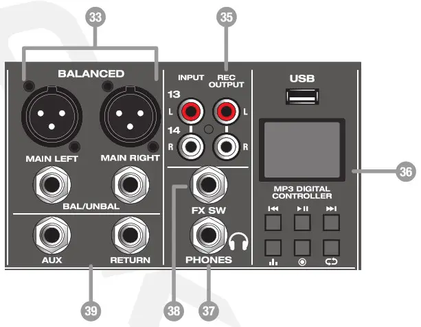
- Main Stereo L/R Outputs: The male XLR connectors provide a balanced line-level signal. Connect these to the left and right inputs of your main power amplifiers, powered speakers, or serial effects processor (like a graphic equalizer or compressor/limiter). TheXLR outputs are 6dB hotter than the TRS outputs.The 44″ TRS output connectors provide balanced or unbalanced line-level signals. Connect these to the next device in the signal chain like an external processor (compressor/limiter), or directly to the inputs of the main amplifier. This is the same signal that appears at theXLR main outputs, but 6dB lower.
- Input: These stereo unbalanced RCA inputs allow you to play a CD player, MP3 player, or another line-level source. The RCAjacks accept an unbalanced signal using standard RCA cables.
- REC Output: The stereo unbalanced RCA outputs allow you to record the main stereo mix onto a hard disk recorder or automatic CD burner. The tape output is the stereo main mix, and it is not affected by the main mix fader. This output can also be used as an extra set of main outputs for feeding another zone.
- MP3 Digital Controller: This interface controls input via the USB interface or Bluetooth connection. It accepts standard USB memory sticks and supports MP3, WMA, and WAV formats. The signal output is mixed to the main via the channel 13/14 (MP3) volume slider (item 32). Play/pause tracks from USB device. Long press to make selections in the main menu.: Short press to choose previous/next tracks. Long press for volume -/+. : Repeat button (single/all/random). : 7 EQ modes: normal, pop, rock, jazz, classic, soft, DBB (USB mode). : Press to enter recording mode.Bluetooth: To listen to music via the Bluetooth wireless connection, you must pair theRPM1470 with your Bluetooth-enabled device.a. Press the play/pause button to enter the main menu.b. Use the previous/next buttons to navigate to the Bluetooth menu. Press the play/pause button to select Bluetooth. The unit will automatically enter pairing mode.c. Make sure your Bluetooth-enabled device is discoverable. Search for and selectRPM1470 is on the list of available devices.d. If pairing is successful you will see this graphic: Music playback can be controlled via the MP3 digital controller or your device.USB: for USB playback, simply plug your thumb drive into the USB slot and the unit will automatically begin to play music.Record to USB:a. Press the record button or navigate through the main menu to the record function. Please make sure there is sufficient space on your USB drive.b. Short press the play button to begin or end recording.c. After recording short press the rec button to save the current recording and prepare for the next recording. Or long-press the play button to save the current recording.d. After recording long-press the rec button to playback the previous recording.Please note: The Main L+R output fader sets the recorded volume when you’re recording to USB. Ifyour recordings are too low or too loud in volume, check the master fader level and adjust it accordingly.Computer Playback:a. connect the computer to the mixer via the USB port.b. Long press play to enter the main menu and select USB Audio.c. Open the music player on the computer to commence playback.
- Headphone Output: This TRS output is used for monitoring the master signal and individually monitoring each channel via the Output Main L/R sliders.
- Foot Switch: This 14″ jack allows for the connection of a footswitch to toggle digital effects on and off.
- AUX/Return: Ifyou wish to connect a processor like a Gate or compressor or another signal processor to the main mix you can send the signal from the Aux send out to the input of the processor device and then send the signal back from the output of the processor device into the Aux return.
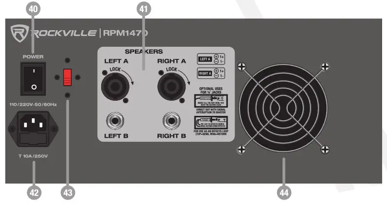
REAR PANEL
- Power Switch
- L/R SpeakOn /%” Outputs: These plugs provide a balanced line-level fully mixed Connect them to your main power amplifiers, powered speakers signal accept 4 ohm or 8-ohm speakers.
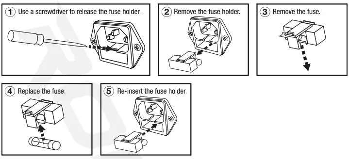
- Power Socket: IEC AC power socket with user-serviceable T10A/250V fuse.
- Variable Voltage Switch: 110/220V switchable power supply.
- Cooling Fan: This fan helps dissipate heat from the unit. Be sure to keep it clear of any obstructions.
CONNECTIONS
Balanced vs. Unbalanced LinesA balanced line is a three-conductor system in which two signal wires carry an equal, but opposite voltage with respect to the ground wire. The ground wire acts only as a shield and does not carry any audio signal current. Outside interference is either shielded from the internal signal conductor or if it gets into the cable is canceled out by the opposite signals at the receiving end. Balanced connections are preferred for long cable runs.
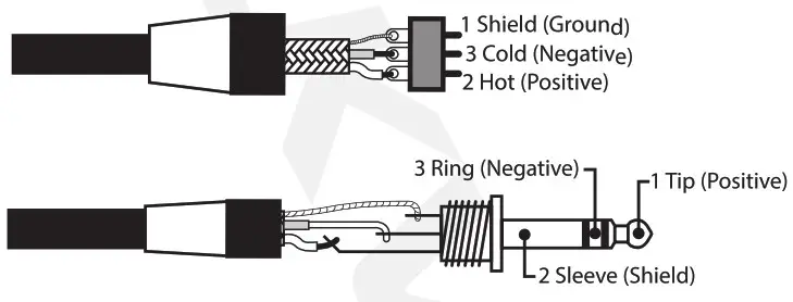 An unbalanced cable is a two-wire system where the shield (ground wire) acts as one of the current-carrying signal conductors. The center conductor enclosed by the shield is commonly known as the “hot” conductor. Unbalanced audio cables do not reject noise as well as balanced lines. Unbalanced lines are typical in-home hi-fi-type systems and on the outputs of electronic musical instruments. These work well if the distance between the components is short, the signal level is relatively high and all of the electronics used in the system are plugged into the same AC outlet.
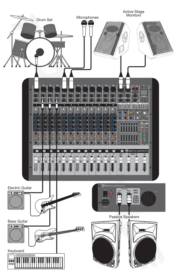
Typical Live Sound Set-Up
Typical Studio Set-Up
BLOCK DIAGRAM

TROUBLESHOOTING
|
PROBLEM |
SOLUTION |
| No power | 1. Make sure the unit is plugged in and the power switch is in the ON position.2. Check that the power cable is plugged in tightly to the unit.3. Check and replace the fuse if necessary. See fuse replacement diagram on the next page. |
| No sound | 1. Check that all appropriate cables are plugged in correctly.2. Check the Master Volume settings.3. Be sure the Volume and Gain of appropriate channels are set above 0 levels and matched correctly.4. Be sure your microphone is on.5. Make sure fader and balance are set to center positions and levels are increased. |
| Turn down the channel gains one by one. If you don’t hear the sound then the problem is either with the channel or whatever device is plugged into it. Unplug the device, to see if the sound disappears.Make sure you are using a proper cable. For ‘A– cables, there are 3 types: instrument, TS (unbalanced), and TRS (balanced). Check the requirements of the connected gear and make sure you are using the appropirate cable. | |
| Buzzing sound | Make sure you are using a proper cable. For W cables, there are 3 types: instrument, TS (unbalanced), and TRS (balanced). Check the requirements of the connected gear and make sure you are using the appropirate cable. |
| Bad Channel | 1. Check that the EQ is set up properly.2. Check channel gain.3. Check channel level.4. Check that the channel pan is set to the 12 o’clock position.5. Try setting up the same source signal on a different channel. Make sure to use the same settings as the suspect channel.6. If using a microphone, make sure that it does not require phantom power. |
| Bad Output | 1. Make sure the main level is turned up.2. Check that the EQ is set up properly.3. Make sure the aux return level is not maxed out4. Unplug devices from other line-level outputs just in case one of the devices has a problem. |
| Bluetooth Pairing Fails | 1. Check to see that both devices are turned on and that your Bluetooth device is discoverable.2. Turn both devices off and then on again.3. Make sure you’ve selected the proper source.4. Make sure that the Bluetooth device is within 5 feet of the unit.5. Move both devices away from other Bluetooth devices, microwaves. wireless routers, and other electronics.6. Make sure that all 3 volume controls are set properly (see Bluetooth section for volume settings).7. Make sure that the unit is not paired to a previously paired device. |
| No USB playback | Make sure that the audio files are in the specified format (MP3, WAV, WMA). |
FUSE REPLACEMENT DIAGRAM
FEDERAL COMMUNICATIONS COMMISSION COMPLIANCE INFORMATIONResponsible party name: RockvilleAddress: 600 Bayview Ave,Entrance A,Inwood, NY 11096
Hereby declares that the product Rockville RPM1470 14 Channel 6000W Powered Mixer complies with FCC rules as mentioned in the following paragraph:
This device complies with Part 15 of the FCC rules. Operation is subject to the following two conditions: (1) this device may not cause harmful interference, and (2) this device must accept any interference received, including interference that may cause undesired operation.
Note: This equipment has been tested and found to comply with the limits for a Class B digital device, pursuant to Part 15 of the FCC rules. These limits are designed to provide reasonable pro- protection against harmful interference in a residential installation. This equipment generates, uses, and can radiate radio frequency energy and, if not installed and used in accordance with the instructions, may cause harmful interference to radio communications. However, there is no guarantee that interference will not occur in a particular installation. If this equipment does cause harmful interference to radio or television reception, which can be determined by turning the equipment off and on, the user is encouraged to try to correct the interference by one or more of the following measures:
- Reorient or relocate the receiving antenna.
- Increase the separation between the equipment and receiver.
- Connect the equipment into an outlet on a circuit different from that to which the receiver is connected.
- Consult the dealer or an experienced radio/TV technician for help.

 report this ad
RockvilleAudio.com© 2020 ROCKVILLE // Features and specifications are subject to change and/or improvement without notice.
[xyz-ips snippet=”download-snippet”]