
RWM132VWireless VHF Microphone SystemOWNER’S MANUAL
Thank you for purchasing this Rockville RWM132V Wireless VHF Microphone System. Please read this owner’s manual carefully for proper use of your Rockville Wireless Microphone System. Should you need technical assistance please call our technical helpline at 1-646-758-0144, Monday through Friday, 9 am to 5 pm EST.
INCLUDES
- (2) wireless handheld microphones
- (1) receiver unit
- Power cable
- User manual
- Batteries
- 25 ft 1/4″ to W Unbalanced Cable
Specs/ FEATURES
- The large display on receiver + digital display on each mic
- The improved high-performance wireless handheld microphone capsule
- Includes transmitter with two handheld, high sensitivity, unidirectional, wireless cardioid microphones
- Featuring a dual filter design to limit feedback and interference
- Ultra-signal stability eliminates unwanted distortion
- Transmitter automatically links to receiver for ease of use
- Use two handheld mics at once with no interference
- Individual microphone volume controls
- Low power consumption for longer battery life
SPECIFICATIONSSYSTEMOperating Range: 150 feet or more Channel: Two ChannelFrequency Range: 210MHz – 270MHzFrequency Response: 40Hz – 18KHzS/N.: >103dB (1KHz-A)Operating Temp: 14°F – 122°FOscillation Mode: Quartz CrystalFrequency Stability: 1-0.005%Modulation Mode: VHFHarmonic Radiation : <65dBmRF Output Power: 10mWPower Voltage: AC 110V/60HzMic Battery: AA x 2RECEIVERSensitivity: (SM=30dB) >2mVAudio Output Impedance: 600 flAudio Output Level.: 0 – 0.5VPower Supply: AC 110V/60HzCurrent Consumption: 50mAAudio Out Connector: 1/4– unbalancedTRANSMITTERFrequency Stability: 10.005%RF Output Power: 10mWModulation Mode: VHFMaximum Deviation Range: t48KHzMicrophone Mode. FixedPower Supply: AA x 2Current Consumption: 35mA*Operating range is subject to environmental conditions. Results may vary.
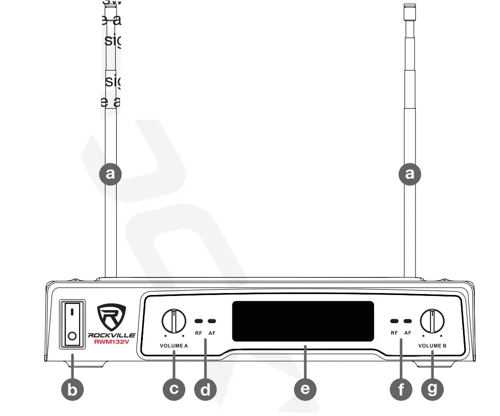
Receiver (Front)
a. Antennasb. Power on/off the itchc. MIC A Volum adjustment knobd. MIC A RF/AF signal LED indicatorse. LCD display f. MIC B RF/AFg. MIC B Volum signal LED indicators adjustment knob
Receiver (Back)
a. Antennasb. XLR Mix out. Please note, do not connect to line-level inputs.c. ¼”Mix out.d. Power cord
Microphone
a. Microphone windscreen.b. LCD displayc. Power on/off switch.d. Battery compartment
Setup and Operation
For the best performance of the wireless microphone system you should make sure that you run the cable from the receiver output (XLR or W mix out) into a line input on a powered speaker or mixing board. If you run it right into a mic level input then the audio level will distort. Most mixers and powered speakers have both a microphone input and a line-level input.
- Plugin and turn on the receiver.
- The receiver should be at least 3′ off the ground for optimal transmission.
- Extend the antennas
- Depending on your setup, connect the appropriate outputs.
- Make sure the microphone batteries are properly inserted.
- Turn on the microphone. It should automatically connect to the receiver.
- Adjust channel volume as necessary.
Tip: To minimize feedback avoid operating the microphones in close proximity of or in front of speakers.
 report this ad
Troubleshooting
|
Problem |
Solution |
| No sound or taint sound |
|
|
|
|
|
| Audio artifacts or dropouts |
|
| Distortion | Reduce microphone channel volume. |
| Transmitter information does not appear on the Receiver LCD | The microphone is off. Please turn it on. |
FEDERAL COMMUNICATIONS COMMISSION COMPLIANCE INFORMATIONResponsible party name: RockvilleAddress: 600 Bayview Ave, Entrance A,Inwood, NY 11096Hereby declares that the product Rockville RWM132V VHF microphone kit complies with FCC rules as mentioned in the following paragraph:This device complies with Part 15 of the FCC rules. Operation is subject to the following two conditions: (1) this device may not cause harmful interference, and (2) this device must accept any interference received, including interference that may cause undesired operation.Note: This equipment has been tested and found to comply with the limits for a Class B digital cis,/ice, pursuant to Part 15 of the FCC rules. These limits are designed to provide reasonable protection against harmful interference in a residential installation. This equipment generates, uses, and can radiate radio frequency energy and, if not installed and used in accordance with the instructions. may cause harmful interference to radio communications. However; there is no guarantee that interference will not occur in a particular installation. if this equipment does cause harmful interference to radio or television reception, which can be determined by turning the equipment off and on, the user is encouraged to try to correct the interference by one or more of the following measures:
- Reorient or relocate the receiving antenna.
- Increase the separation between the equipment and receiver.
- Connect the equipment into an outlet on a circuit different from that to which the receiver is connected.
- Consult the dealer or an experienced radio/TV technician for help.
Visit us at:RockvilleAudio.comDue to constant improvements, these specifications are subject to change without notice.Copyright 2020
[xyz-ips snippet=”download-snippet”]