ROLLS CL151 GLC Compressor/Limiter/ Gate User Guide
INTRODUCTION
Thank you for your purchase of the CL151 GLC Gate Compressor Limiter. This unit provides smooth, soft-knee compression and limiting with a gate. Gain reduction is indicated via a front panel 5-segment LED bar graph. Plus, the unit has a mic preamp input with phantom power available.WARRANTY INFO Please visit our website, www.rolls.com, for the Rolls 1 Year Warranty information and registration.
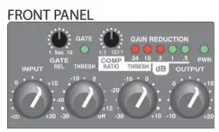
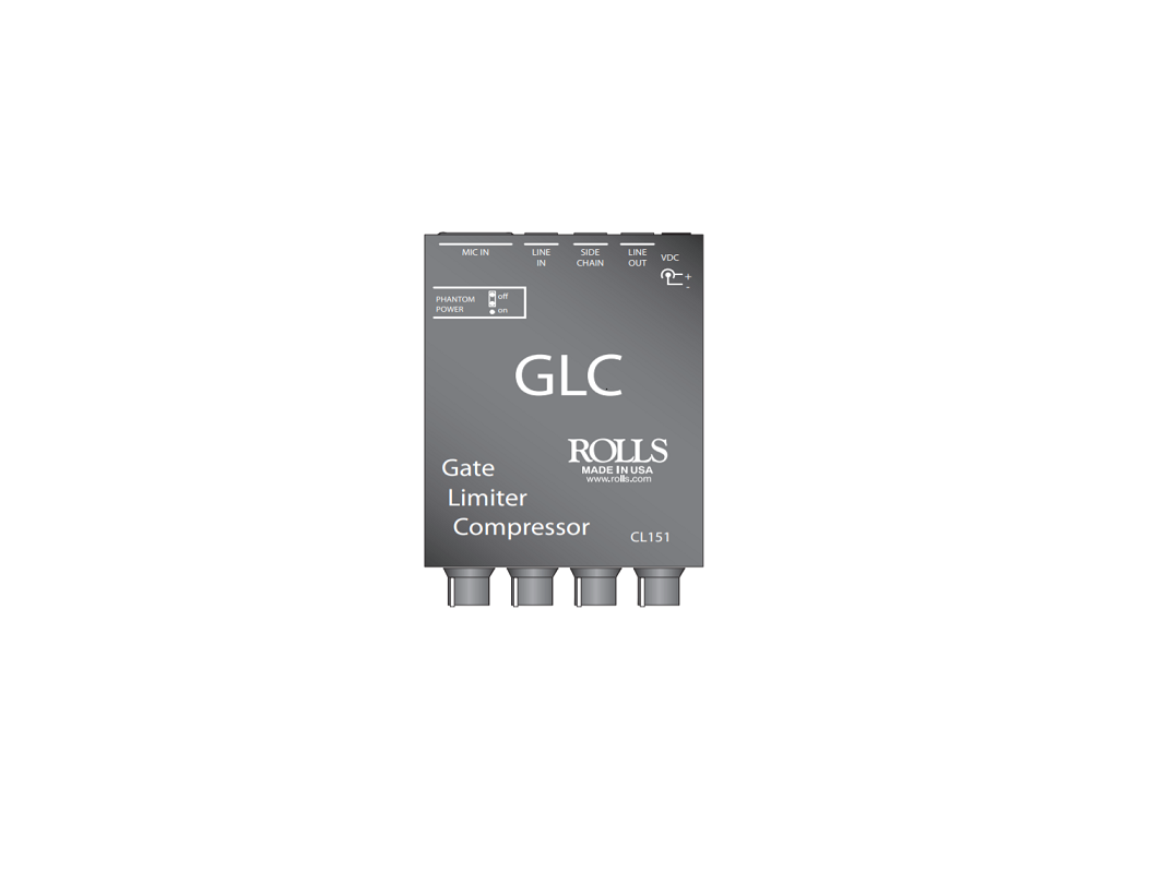
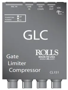
INPUT: Adjusts the amount of input signal to the CL151, from no signal to +20 dB.GATE REL: This control adjusts the amount of time taken for the gate circuitry to “close” or mute the output, after the signal level has dropped below the gate Threshold level.THRESH: Sets the point at which the input signal must surpass to “open” the gate circuitry or allow signal to pass to the output. GATE LED: When lit, indicates that the gate is “closed” or the output is muted.COMP RATIO: This control sets the signal to compression ratio. This ratio relates to the amount of increase of input compared to output signal. Thus, at a 1:1 ratio, a 1 dB increase of input signal will result in a 1 dB increase of output signal. At 2:1, a 2 dB increase of input signal will result in only 1 dB increase of output signal. At 8:1, an 8 dB increase of input signal will result in a 1dB increase of output signal. THRESH: Sets the point that the input signal must reach for compression to begin.GAIN REDUCTION LED’s: This LED ladder indicates the amount of signal compression, or gain reduction. OUTPUT: Adjusts the amount of overall output signal from the CL151. PWR: Indicates that the CL151 is connected to the power source, and the unit is on.REAR PANEL MIC IN: Balanced XLR jack, for connection to any standard dynamic or condenser microphone.LINE IN: Balanced 1/4″ TRS jack for connection to balanced or unbalanced line level signals. SIDE CHAIN: 1/4″ TRS jack for connection via TRS insert cable to a device such as an equalizer or other device, for direct access to the CL151 detector circuitry. LINE OUT: Balanced 1/4″ TRS jack for connection to a mixer’s line input or to an amplifier. DC IN: For connection to the Rolls PS27s 15 VDC, power supply; outside of the barrel is positive.SIDE PANEL PHANTOM POWER: Switch for connecting phantom power to the XLR Mic Input.
CONNECTION AND OPERATION
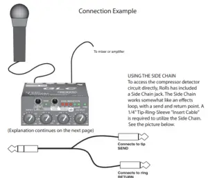
The example below shows the connection of a microphone. If the microphone requires phantom power, make sure the Phantom Power is on. Connect the output of the CL151 via a balanced or unbalanced 1/4″ plug to the input of a mixer or amplifier.Begin adjustments by setting the INPUT and OUTPUT levels at O (about 10 O’clock). This setting is for “unity gain”.Set the gate THRESH for “off”, the COMP RATIO for 1:1, and the compressor THRESH for +10. These initial settings essentially bypass the gate and compressor circuits.The compressor RATIO and THRESH controls work together to control the amount of compression, and the point at which compression begins respectively. Decreasing the THRESH control lowers the amount of signal required to begin compression – so it compresses sooner. This works with the RATIO control which, when increased, increases the amount of compression.The gate THRESH control, after being turned slightly counterclockwise from the “off” position, goes to its maximum level. This means it requires a higher signal level to “open” the gate. As the gate THRESH control is turned counterclockwise, a lower and lower signal is required to open the gate.The gate REL (release time) control sets the amount of time taken for the gate to “close” after the signal drops below the THRESH level. For example, the CL151 will continue passing a sustaining note until the level drops below the THRESH level, and the REL time has passed.
 report this ad
The plug connected to the Tip is the “Send” which will connect to the Input of the signal processing device, and the Ring is the “Return” which connects directly to the detector (compression control) circuit.Side Chain circuits are often used in “ducking”. Ducking is momentarily lowering one signal under another signal. For example, you may wish to automatically lower a music signal under a paging microphone signal, then have the music return to normal level after the page is over. This would be accomplished by running the music into the compressor, and having the page signal connect into the Side Chain return. The page signal must also be connected to the main mixer or amplifier as well. When the paging signal begins, its signal goes to the main mixer and the Side Chain circuitry. The music is compressed or “ducked” under the page.
Read More About This Manual & Download PDF:
References
[xyz-ips snippet=”download-snippet”]