ROLLS HR70 Digital FM Transmitter User Guide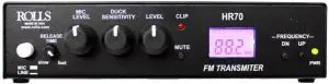
Multi path reflectionsFM waves, like light waves, travel in a straight direction unless reflected off objects in their path. Because of this, two sets of waves reach your antenna from the FM station; those that have traveled directly to the antenna, and those that have been reflected off buildings or mountains.When the antenna receives both kinds of signals, the two interfere with each other and result in distorted sound and poor separation. This phenomenon is called “multi path reflection”. To reduce this problem, select an antenna with good directivity and place it in the best location with strong reception.
SPECIFICATIONS
- Frequency Response: 20 Hz – 12.5 kHz
- Input Impedance: 100KΩ Unbalanced, 600Ω Balanced
- Indicators: Power LED and Clip LED
- Input/Output jacks: XLR balanced INPUTRCA unbalanced input and output
- Power: Rolls PS27s 12 – 15 VDC 500mA
- Antenna Jack: BNC connector
- Antenna Impedance: 50Ω
- Tuning Range: 88 – 108 MHz
- Dimensions: 6.75″w x 4.25″d x 1.6″h
- Weight: 1.5 lbs
This device complies with Part 15 of the FCC Rules. Operation is subject to the following two conditions: (1) this device may not cause harmful interference, and (2) this device must accept any interference received, including interference that may cause undesired operation.
Changes or modifications of any kind to the Rolls HR70 or its included antenna are not approved or permitted in any way, and could void the user’s authority to operate the equipment.
Read this!
- Antenna must be straight. Do not place the antenna on the ground. Do not connect antenna to anything metal.
- You will need to try different broadcast frequencies to get the best transmissionrange. Do not transmit on a frequency that has any broadcast material as it will interfere with your transmission range.
- Antenna should be higher for better transmitting range. Any objects especially metal between the transmitter and receiver will negatively affect broadcast range. Using the 6′ extension cable is optimal, longer lengths will decrease range.
INTRODUCTION
Thank you for your purchase of the Rolls HR70 FM Digital Transmitter. This unit has been carefully designed and assembled to provide years of reliable FM transmission. Please read this manual carefully as it contains important information regarding the proper setup and operation of the HR70. This unit complies with FCC part 15 rules.
INSPECTION
Unpack and Inspect the package. Your HR70 was carefully packed at the factory in a protective carton. Nonetheless, be sure to examine the unit and the carton for any signs of damage that may have occurred during shipping. If obvious physical damage is noticed, contact the carrier immediately to make a damage claim.
WARRANTY
For complete Warranty information and registration, please visit our web site; www.rolls.com. Click on the REGISTER YOUR WARRANTY HERE line.
DESCRIPTION
FRONT PANEL
- DISPLAY: LCD display showing the active information relevant to the current operation of the HR70.
- MIC/LINE: When pressed in, the gain of the XLR Mic In is reduced by 30 dB.
- CLIP: LED for indication of when the circuit is over driven/clipping.
- MUTE: When pressed unit will MUTE.
- LEVEL: Adjusts the level of output.
- FREQUENCY UP / DN: Selects the frequency that the HR70 is transmitting.
- RELEASE TIME: Adjusts the amount of time for the “ducked” signal to return to its normal level.Counterclockwise; slow – Clockwise; fast.
- MIC LEVEL: Adjusts the amount of gain for the Mic In circuit.
- DUCK SENSITIVITY: The Threshold at which “ducking” begins. When the microphone level reaches the threshold, the signal present at the Line In jacks is reduced until the announcement is over, then the Line In signal returns to its previous level.
A NOTE ON THE HR70 THRESHOLD SETTING, WITH THE SENSITIVITY CONTROL FULLY CLOCKWISE: If a signal is on the XLR input, the ducking will begin (the threshold is) at -30 dB when the Mic/Line switch is set to “Mic”, and 0 dB when the switch is set to “Line”. If the control signal is on the RCA input, ducking begins at -30 dB.
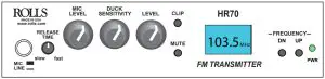
HR70 DISPLAY
- Channel Mhz – indicates Megahertz of FM transmission being sent
- Mute indicator
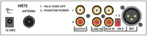
REAR PANEL
- 15VDC: USE THE ROLLS SUPPLIED PS27s ADAPTER ONLY!!!
- Aux In: The Aux in is an input that will talk over the Line In (Main input)
- Line in: This is the main line level input to the HR70.
- Outputs: RCA stereo outputs.
- Mic: XLR microphone input.
- ANTENNA: Connects to the included BNC FM transmitting antenna.

CONNECTION
- Connect the Rolls supplied adapter to the VDC power jack of the HR70, then to an AC outlet with the proper voltage.
- Connect the HR70 Left and Right line input to a mixer, or other audio device.
WE RECOMMEND TURNING THE DUCK SENSITIVITY FULLY CLOCKWISE (ALL THE WAY UP) TO START. THIS IS THE HIGHEST SENSITIVITY AND MOST DUCKING AVAILABLE ON THE UNIT.
OPERATION
 report this ad
If you are using a condenser microphone, switch the Phantom Power on. Set the level of the music signal (Line In) for a comfortable level. Speak into the microphone and adjust the Mic Level for a comfortable level, then adjust the Sensitivity so that the music is muted when speaking with a normal voice. Set the Release Time control for the amount of time you wish for the Aux In signal to return to normal.
References
[xyz-ips snippet=”download-snippet”]