

30-Gallon Fuel Caddy Gasoline Compatible

Owner’s Manual
WARNING: Read carefully and understand all ASSEMBLY AND OPERATIONINSTRUCTIONS before operating. Failure to follow the safety rules and other basic safety precautions may result in serious personal injury.Item #20632
READ & SAVE THESE INSTRUCTIONS
Thank you very much for choosing a RoughneckTM product! For future reference, please complete the owner’s record below:Serial Number/Lot Date Code:Purchase Date:Save the receipt, warranty, and this manual. It is important that you read the entire manual to become familiar with this product before you begin using it. This fuel caddy is designed for certain applications only. Northern Tool and Equipment is not responsible for issues arising from modification or improper use of this product such as an application for which it was not designed. We strongly recommend that this product not be modified and/or used for any application other than that for which it was designed. For technical questions, please call 1-800-222-5381.
Intended Use
The rugged UL listed 30-Gallon, cart-style, steel fuel caddy allows for easy maneuverability, letting you bring the fuel source directly to the need for easy dispensing at home or in the field. This red model is color coded and designed for use with gasoline type fuels. It is the perfect choice for auto repair, farm, lawn and garden, small engine, motorcycle/ATV, marine uses, and more. It is UL-listed and OSHA-approved for safe, temporary storing and transferring of fuel.
Packaging Contents
- Fuel caddy tank includes preassembled wheels (2), fuel gauge with vent, plastic nut, handle mounting hardware (2), and ground wire mounting screw
- Handle
- Hose
- Fill tube and cap
- Fuel gauge lens and rubber washer
- Ground wire
- Front foot pad (2)
- Rotary Pump UL-listed includes handle, nut, washer
- M6 x 25mm Philips head screws (4)
- Roll of PTFE tape
- Decal set
- Owner’s Manual
Technical Specifications
Property |
Specification |
|
Tank Maximum Capacity |
30 gal (114 L) |
|
Pump Type |
Rotary vane positive displacement, UL-listed |
|
Pump Weight |
13 lb. (5.9kg) |
|
Pump Output Rate |
7.4gpm (28Lpm) at 100rpm |
|
Dimensions |
24 ½” x 22” x 41 ½” |
|
Weight (empty) |
107 lb. |
|
Compatible Fluids |
Gasoline |
|
Hose Length |
8 ft |
|
Wheel Size |
10” semi-pneumatic |
Important Safety Information
WARNING
- Read and understand all instructions. Failure to follow all instructions may result in serious injury or property damage.
- The warnings, cautions, and instructions in this manual cannot cover all possible conditions or situations that could occur. Exercise common sense and caution when using this tool. Always be aware of the environment and ensure that the tool is used in a safe and responsible manner.
- Do not allow persons to operate or assemble the product until they have read this manual and have developed a thorough understanding of how it works.
- Do not modify this tank or product in any way. Unauthorized modification may impair the function and/or safety and could affect the life of the product. There are specific applications for which the product was designed.
- Use the right tool for the job. DO NOT attempt to force small equipment to do the work of larger industrial equipment. There are certain applications for which this equipment was designed. This product will be safer and do a better job at the capacity for which it was intended. DO NOT use this equipment for a purpose for which it was not intended.
- Industrial or commercial applications must follow OSHA requirements.
WARNING
WORK AREA SAFETY
- Inspect the work area before each use. Keep work area clean, dry, free of clutter, and well-lit. Cluttered, wet, or dark work areas can result in injury. Using the product in confined work areas may put you dangerously close to cutting tools and rotating parts.
- Do not use the product where there is a risk of causing a fire or an explosion; e.g., in the presence of flammable liquids, gases, or dust. The product can create sparks, which may ignite the flammable liquids, gases, or dust.
- Do not allow the product to come into contact with an electrical source. The tool is not insulated and contact will cause electrical shock.
- Keep children and bystanders away from the work area while operating the tool. Do not allow children to handle the product.
- Be aware of all power lines, electrical circuits, water pipes, and other mechanical hazards in your work area. Some of these hazards may be hidden from your view and may cause personal injury and/or property damage if contacted.
WARNINGPERSONAL SAFETY
- Stay alert, watch what you are doing, and use common sense when operating the tool. Do not use the tool while you are tired or under the influence of drugs, alcohol, or medication. A moment of inattention while operating the tool may result in serious personal injury.
- Dress properly. Do not wear loose clothing, dangling objects, or jewelry. Keep your hair, clothing and gloves away from moving parts. Loose clothes, jewelry, or long hair can be caught in moving parts. Air vents on the tool often cover moving parts and should be avoided.
- Wear the proper personal protective equipment when necessary. Use ANSI Z87.1 compliant safety goggles (not safety glasses) with side shields, or when needed, a face shield. Use a dust mask in dusty work conditions. Also use non-skid safety shoes, hardhat, gloves, dust collection systems, and hearing protection when appropriate. This applies to all persons in the work area.
- Do not overreach. Keep proper footing and balance at all times.
- Remove keys or wrenches before connecting the tool to an air supply, power supply, or turning on the tool. A wrench or key that is left attached to a rotating part of the tool may cause personal injury.
- Secure the work with clamps or a vise instead of your hand when practical. This safety precaution allows for proper tool operation using both hands.
CAUTIONFUEL CADDY USE AND CARE
- Do not force the fuel caddy. Products are safer and do a better job when used in the manner for which they are designed. Plan your work, and use the correct product for the job.
- Check for damaged parts before each use. Carefully check that the product will operate properly and perform its intended function. Replace damaged or worn parts immediately. Never operate the product with a damaged part. Ensure that all fittings and threaded connections are tightened and leak free.
- Do not use a product with a malfunctioning switch. Any power tool that cannot be controlled with the power switch is dangerous and must be repaired by an authorized service representative before using.
- Disconnect the power/air supply from the product and place the switch in the locked or off position before making any adjustments, changing accessories, or storing the tool. Such preventive safety measures reduce the risk of starting the tool accidentally.
- Store the product when it is not in use. Store it in a dry, secure place out of the reach of children. Inspect the tool for good working condition prior to storage and before re-use. Store in well ventilated area. Do not store in vehicle or living space. Do not store in direct sunlight.
- Use only accessories that are recommended by the manufacturer for use with your product. Accessories that may be suitable for one product may create a risk of injury when used with another tool. Never use an accessory that has a lower operating speed or operating pressure than the tool itself.
- Keep guards in place and in working order. Never operate the product without the guards in place.
- Do not leave the tool running unattended.
Specific Operation WarningsDANGER
EXTREMELY FLAMMABLE VAPORS CAN EXPLODEHARMFUL OR FATAL IF SWALLOWED
- If swallowed, do not induce vomiting, call physician immediately.
- Keep out of reach of children.
- Avoid prolonged breathing of vapors.
- Do not siphon by mouth.
- Do not store in vehicle or living space.
- Store and use in a well-ventilated area.
- Vapors can be ignited by a spark or flame source many feet away.
- Keep away from flame, pilot lights, stoves, heaters, electric motors, and other sources.
- Keep container closed.
WARNING
- Always wear the proper protective equipment including ANSI Z87.1 compliant eye protection and heavy duty work gloves.
- Discard static electricity before fueling by touching a metal surface away from the nozzle. · Fill slowly to prevent the build-up of static charges.
- If fire starts, do not remove nozzle. Back away immediately.
- Closely monitor flow to prevent spills and overflow.
- Keep nozzle in contact with the container while filling. Do not use a nozzle lock-open device.
- Attach ground wire and bond containers that are being pump from and into. Ground all containers to a known ground source to dissipate static electricity before pumping liquids. · Always empty the pump and hose after use lifting the hose and turning the handle in the opposite direction of the arrow to empty all remaining liquids back into the caddy.
- Use cart for “one type of fuel only” to avoid possible contamination or damage to equipment or motor vehicles. Do not use this container for gasoline or other flammable liquids.
- Place caddy on firm, level, stable ground before use. Do not attempt fuel transfer if caddy is stable or on an inclined surface.
- Never leave unit unattended while operating.
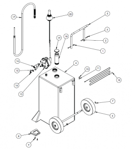
Main Parts of Fuel Caddy
|
Part No. |
Part Description |
Quantity |
| 1 | M6 nylon insert locknut (preassemblied on tank) | 2 |
| 2 | M6 flat washer (preassemblied on tank) | 2 |
| 3 | M6 shoulder bolt (preassemblied on tank) | 2 |
| 4 | 30 gallon fuel tank | 1 |
| 5 | Tank handle | 1 |
| 6 | 10 rear wheel | 2 |
| 7 | 19mm retaining ring | 4 |
| 8 | Front foot pad | 2 |
| 9 | M6 x 25 bolt | 4 |
| 10 | Ground screw (preassemblied on tank) | 1 |
| 11 | Ground washer (preassemblied on tank) | 1 |
| 12 | Ground wire | 1 |
| 13 | Rotary hand pump | 1 |
| 14 | Pump handle | 1 |
| 15 | M16 washer | 1 |
| 16 | M16 nylon insert locknut | 1 |
| 17 | Hose assembly | 1 |
| 18 | Fill tube | 1 |
| 19 | Fill cap | 1 |
| 20 | Fuel level gauge assembly | 1 |
Assembly Instructions
Tools Required
- 27 mm open end wrench
- Phillips head screwdriver
- 24mm socket or wrench
Tools Included
- 4mm hex wrench
- 5mm hex wrench
- 10mm socket or wrench
- Retaining ring pliers
- PTFE tape
- Remove the caddy tank, pump, handle, fuel gauge, fill tube, wheel and accessory kits from the carton.
- Remove M6 nylon insert nut [1], washers [2] and shoulder bolts [3] from tank [4]. Assemble handle [5] and reinstall hardware to tank. The shoulder bolt head must be on the outside of the handle to properly secure the handle. Tighten securely using 5mm hex wrench and 10mm wrench.
- Tilt caddy onto its front (handle up) to install rear wheels [6]. Install retaining ring [7] to inner axle groove using retaining ring pliers. Add wheel and second retaining to outer groove. Repeat on second side.
- Tilt caddy onto its back (handle down) to install the front foot pads [8]. Note the pads are the same for the left and right foot. Place a pad on each foot, flipping as required to match the foot bracket. Install (2) M6x25mm bolts [9] and tighten with 4mm hex wrench.
- Remove ground screw [10] and washer [11] from tank (by right handle tab). Assemble green ground wire [12] to tank by placing the screw through the connector and threading the screw into the ground tab on the tank using Phillips head screwdriver. Make certain the connection is securely tightened.
- Remove all plastic caps from tank and pump. Wrap 3/4″ male pipe threads on top of tank with PTFE tape.
- Assemble pump [13]: Place handle [14], M16 washer [15] and M16 nut [16] onto shaft, tightening with 24mm socket or wrench.
- Thread pump onto tank (place the side marked “IN” onto 3/4″ pipe thread). Rotate to tighten by hand and stop with handle facing outside of tank.
- Wrap 3/4″ fitting on hose [17] with PTFE tape and thread onto pump. Tighten with 27mm open end wrench.
- Wrap 2″ thread on fill tube [18] with PTFE tape and thread onto tank. Tighten by hand until secure and install fill cap [19].
- Install fuel level gauge assembly [20]: Thread assembly into tank. Tighten with adjustable friction spanner wrench until mark is pointing toward opposite corner of the tank.
Operating InstructionsWARNING
- If swallowed, do not induce vomiting, call physician immediately.
- Avoid prolonged breathing of vapors.
- Do not syphon by mouth.
- Always wear the proper protective equipment including ANSI Z87.1 compliant eye protection and heavy duty work gloves.
- Fill slowly to prevent the build-up of static charges.
- If fire starts, do not remove nozzle. Back away immediately.
- Closely monitor flow to prevent spills and overflow.
- Keep nozzle in contact with the container while filling. Do not use a nozzle lock-open device.
- Use cart for “one type of fuel only” to avoid possible contamination or damage to equipment or motor vehicles. Do not use this container for gasoline or other flammable liquids.
- Place caddy on firm, level, stable ground before use. Do not attempt fuel transfer if caddy is stable or on an inclined surface.
- Drain all fuel from hose and pump back into tank by lifting the hose end above the pump and turning the pump handle counter-clockwise.
- Never leave unit unattended while operating.
- Attach green ground wire clamp to a known grounding point on the vehicle being serviced.
- Place the hose in the vehicle.
- Rotate the pump handle to begin the transfer. Pump will self-prime.
- Rotate the handle clockwise (as shown by arrow on the pump) to dispense from the fuel caddy. Rotate counter-clockwise to transfer fuel into the caddy.
- The fuel caddy may also be filled by removing the fill cap and filling through the fill tube. DO NOT OVERFILL. Fuel level must be below the flame arrestor screen under the fill tube.
After Each UseWARNING
- Keep out of reach of children.
- Store in a well-ventilated area.
- Do not store in a vehicle or living space.
- Do not store near heat spark or flame.
- Do not store in direct sunlight.
- Return fuel in hose and pump to caddy by raising hose and slowly turning pump handle in counter-clockwise direction until all fuel is returned to the caddy.
- Move and store caddy to well-ventilated storage area away from living spaces and away from direct sunlight.
Maintenance
- Spray light petroleum-based lubricant inside pump before prolonged storage by removing the hose assembly and spraying directly into the pump port.
- Turn pump handle counter-clockwise to distribute oil inside pump surfaces.
- Reassemble hose.
Maintain the caddy by adopting a program of conscientious repair and maintenance in accordance with the following recommended procedures. It is recommended that the general condition of any tool be examined before it is used. Keep your tool in good repair. Keep handles dry, clean, and free from oil and grease. The following chart is based on a normal operation schedule.
|
Maintenance Interval |
Maintenance Point |
|
Daily before operating |
|
|
After the first 20 operating hours |
Inspect to be sure handle and foot bolts are tight and secure and if not, re-tighten. |
Troubleshooting
Use the table below to troubleshoot problems before contacting service personnel or your local dealer. If the problem continues after troubleshooting, call your local dealer for assistance.
|
Failure |
Possible Cause |
Corrective Action |
|
Fuel gauge float travel restricted. |
Gauge/vent assembly rotated causing flow to interfere with tank sidewall. |
Rotate vent. Check function by removing the gauge nut and lens. Lift indicator disk/rod up and down to verify range of motion. |
Parts Diagram
 Parts List
 Parts List
|
Parts List |
|
Reference |
Part Number |
Part Description |
Quantity |
|
1 |
– |
Tank |
1 |
|
2 |
30GC-HRK |
Handle |
1 |
|
3 |
included with 30GC HRK |
M6 Shoulder bolt |
2 |
|
4 |
included with 30GC HRK |
M6 Flat washer |
2 |
|
5 |
Included with 30GC HRK |
M6 Nylon insert lock nut |
2 |
|
6 |
30GC-WRK |
Wheel |
2 |
|
7 |
included with 30GC HRK |
19 mm Retaining ring |
4 |
|
8 |
30GC-08 |
Fuel gauge assembly with vent |
1 |
|
9 |
30GC-09 |
Fill tube with cap |
1 |
|
10 |
30GC-FRK |
Front foot pad |
2 |
|
11 |
30GC-FRK |
M6 x 25 mm Flanged button head screw |
4 |
|
12 |
JDI-35-UL |
Rotary hand pump – UL-listed |
1 |
|
13 |
80-593-NI |
Hose assembly |
1 |
|
14 |
80-573 |
Ground wire assembly |
1 |
|
15 |
– |
M6 x 12 Phillips head screw with washer |
1 |
Replacement Parts
- For replacement parts and technical questions, please call Customer Service at 1-800-222-5381.
- Not all product components are available for replacement. The illustrations provided are aconvenient reference to the location and position of parts in the assembly sequence.
- When ordering parts, the following information will be required: item description, item model number, item serial number/item lot date code, and the replacement part reference number.
- The distributor reserves the rights to make design changes and improvements to product lines and manuals without notice.
Limited Warranty
Northern Tool and Equipment Company, Inc. (“We” or “Us”) warrants to the original purchaser only (“You” or “Your”) that the Roughneck product purchased will be free from material defects in both materials and workmanship, normal wear and tear excepted, for a period of one year from date of purchase. The foregoing warranty is valid only if the installation and use of the product is strictly in accordance with product instructions. There are no other warranties, express or implied, including the warranty of merchant ability or fitness for a particular purpose. If the product does not comply with this limited warranty, Your sole and exclusive remedy is that We will, at our sole option and within a commercially reasonable time, either replace the product or product component without charge to You or refund the purchase price (less shipping). This limited warranty is not transferable.
Limitations on the WarrantyThis limited warranty does not cover: (a) normal wear and tear; (b) damage through abuse, neglect, misuse, or as a result of any accident or in any other manner; (c) damage from misapplication, overloading, or improper installation; (d) improper maintenance and repair; and (e) product alteration in any manner by anyone other than Us, with the sole exception of alterations made pursuant to product instructions and in a workmanlike manner.
Obligations of PurchaserYou must retain Your product purchase receipt to verify date of purchase and that You are the original purchaser. To make a warranty claim, contact Us at 1-800-222-5381, identify the product by make and model number, and follow the claim instructions that will be provided. The product and the purchase receipt must be provided to Us in order to process Your warranty claim. Any returned product that is replaced or refunded by Us becomes our property. You will be responsible for return shipping costs or costs related to Your return visit to a retail store. Remedy Limits Product replacement or a refund of the purchase price is Your sole remedy under this limited warranty or any other warranty related to the product. We shall not be liable for: service or labor charges or damage to Your property incurred in removing or replacing the product; any damages, including, without limitation, damages to tangible personal property or personal injury, related to Your improper use, installation, or maintenance of the product or product component; or any indirect, incidental or consequential damages of any kind for any reason.
Assumption of Risk You acknowledge and agree that any use of the product for any purpose other than the specified use(s) stated in the product instructions is at Your own risk. Governing Law
This limited warranty gives You specific legal rights, and You also may have other rights which vary from state to state. Some states do not allow limitations or exclusions on implied warranties or incidental or consequential damages, so the above limitations may not apply to You. This limited warranty is governed by the laws of the State of Minnesota, without regard to rules pertaining to conflicts of law. The state courts located in Dakota County, Minnesota shall have exclusive jurisdiction for any disputes relating to this warranty.
Distributed by: Northern Tool & Equipment Company, Inc.Burnsville, Minnesota 55306 www.northerntool.com Made in China
[xyz-ips snippet=”download-snippet”]