![]()
![]()
Low Cost 360 Degree Laser Range ScannerDevelopment kit User ManualModel: A3M1www.slamtec.com
Overview
RPLIDAR A3 development kit includes the matched tools used for evaluating RPLIDAR’s performance and initial development. After connecting the RPLIDAR A3 with PC via USB cable and connecting the power adapter to the USB cable, users can observe the cloud map of the environment scanning point collected by the RPLIDAR in RoboStudio and start development based on the SDK.
Items in the Development KitRPLIDAR Development Kit contains:
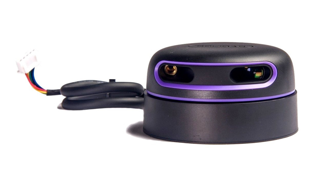
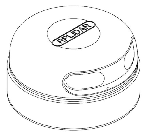
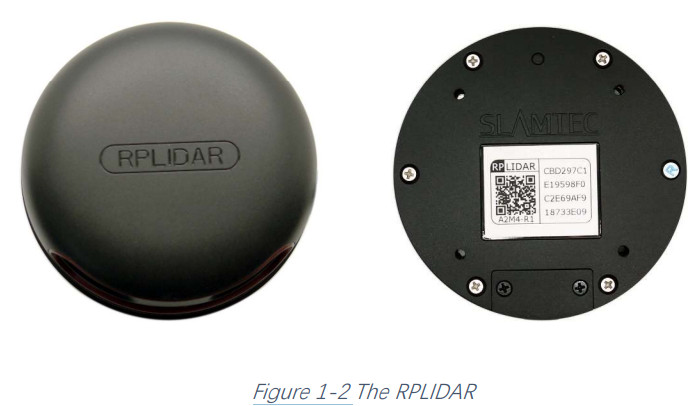
- RPLIDAR(PWM motor driver embedded)
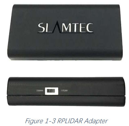
- USB Adapter
- Micro-USB cable
- Power cable

The RPLIDAR A3 development kit contains a standard RPLIDAR A3 unit (A3M1). The RPLIDAR is embedded with logic IO drivable motor controller which can be used to configure the scan frequency by tuning motor speed. Developers can also choose to turn off the motor for power-saving purposes. RPLIDAR usage and interface definition will be introduced in the coming sections.
 USB AdapterThe USB adapter comes with a dial switch. It can be used to switch the Baud rate from 115200 to 256000 or vice versa, which is compatible with RPLIDAR A3 and the former RPLIDAR series. Please note that the Baud rate should be set as 256000 if the USB adapter is connected with RPLIDAR A3.
Connection and Usage
ConnectionRPLIDAR A3 can be easily connected to PC according to the following steps.
- Connect RPLIDAR A3 with the USB adapter.

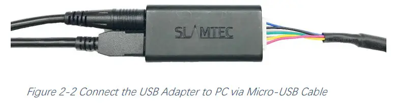
- Connect the USB adapter to your PC via the Micro-USB cable. If the PC is on, after connecting the USB cable to your PC and connecting the power adapter to the USB cable, the indicator light of the USB will light up but the RPLIDAR will not start scanning.

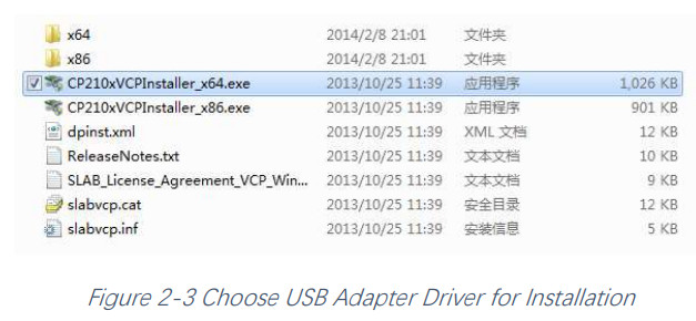
Install Driver for the USB AdapterThe USB adapter converts UART to USB by using a CP2102 chip. You need to install the device driver for the chip. The driver can be found in the provided SDK package or downloaded from Silicon Labs’ official website: http://www.silabs.com/products/mcu/Pages/USBtoUARTBridgeVCPDrivers.aspx Here are the installation steps in Windows: after connecting the RPLIDAR with PC, please find the driver file “CP210x VCP Windows” and choose the correct operating system version accordingly: x86 for 32-bit OS and x64 for 64-bit OS.

After Installing the driver according to the above installation steps, you will see the corresponding serial port name in the [Control Panel] -> [Device and Printers]. Please refer to the below figure.

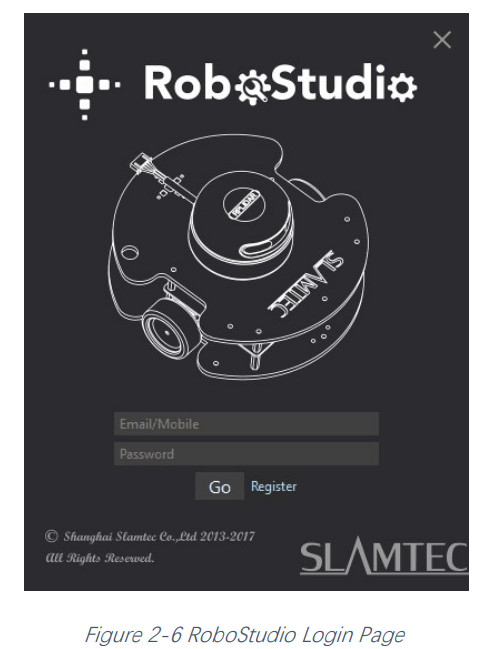
Run Demo ApplicationSLAMTEC provides a Lidars plugin in RoboStudio for users in test and evaluation. You can view the scan result directly in the UI and save the scan result to files for further processing.This GUI demo can only run under Windows. For Linux and macOS users, please refer to the other simple demo provided in the SDK. Please make sure you have connected RPLIDAR to the PC by using a USB adapter and installed the device driver correctly before running the demo application in RoboStudio. Launch RoboStudio and log in.
 If the connection is ok, you shall see the user interface is shown as below.
- Click File->Lidars to open the lidar control panel in the left;
- Click Serial Ports to extend the lidar lists and you’ll find the RPLIDAR A3 previously connected to your PC;
- Click the RPLIDAR A3 icon to extend the tool buttons below the icon: the left one is to adjust the motor speed while the right one is to open the toolbar in the major work area as shown in Figure 2-7.
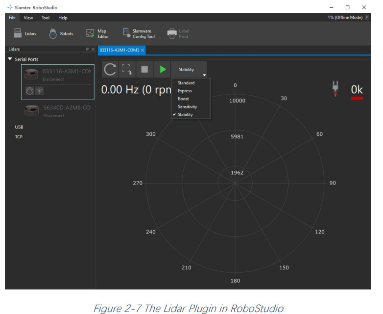
The serial number, version, and model of the RPLIDAR A3 will show next with its icon in the lidar control panel. The supported commands of RPLIDAR are shown in the toolbar. The descriptions are listed in the bellow table.
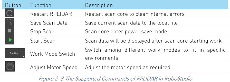
Press the Start Scan button![]() the scan data will be displayed as below(by default, the motor rotating speed should be about 10Hz.):
the scan data will be displayed as below(by default, the motor rotating speed should be about 10Hz.):
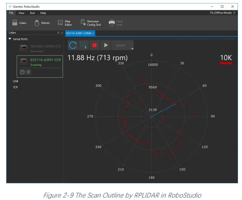
Right-click in the major working area to choose a range so as to zoom in or out the view.The scan frequency is also shown in the above interface.
Troubleshooting
When the scan core or the laser power works abnormally, the scan core will enter protection mode. This state can be retrieved via SDK API. If such a scenario happened, please send a restart command ![]() to reset the scan core.
to reset the scan core.
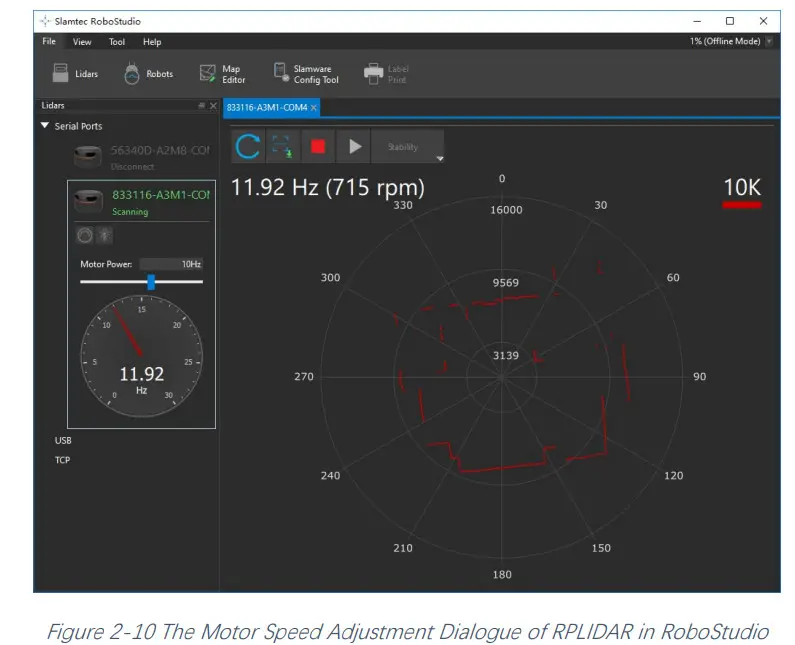
Motor Speed AdjustmentDuring the running process, different motor rotating speeds can be achieved by pressing![]() the button, which can fit in different working environments or meet specific requirements. There will be a speed adjustment dialog box and a dashboard popped up for users to enter the required speed. After entering a value, the motor will work at the settled rotating speed automatically. Users can also drag the sliding handle to the required rotating speed.
the button, which can fit in different working environments or meet specific requirements. There will be a speed adjustment dialog box and a dashboard popped up for users to enter the required speed. After entering a value, the motor will work at the settled rotating speed automatically. Users can also drag the sliding handle to the required rotating speed.
The current actual rotating speed will show in the upper left corner of the major work area. For instance, the actual rotating speed in the following screenshot is 11.92Hz.
SDK Introduction and Usage
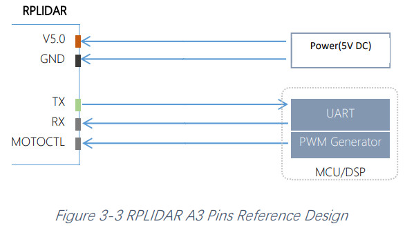
RPLIDAR A3 Pin Definition and SpecificationRPLIDAR A3 is using an XH2.54-5P specification plug. Please use it with a socket that meets the specification of XH2.54-5P. The detailed pin definition is shown as below:

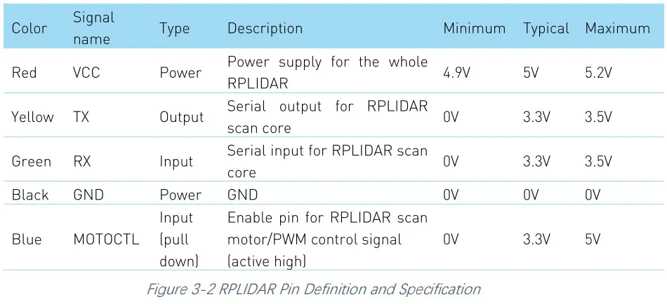
RPLIDAR A3 uses the one 5V DC power supply for powering the scan motor and the scan core at the same time. No extra power is required. With a build-in and speed-adjustable motor driver, RPLIDAR A3 can control the start, the stop, and the rotating speed of the motor via the MOTOCTL signal.
- Reference Design for RPLIDAR development
Pin Definition for the USB AdapterThe USB adapter is also using an XH2.54-5P specification socket, and it can be connected with RPLIDAR A3 directly. The pin definition is the same as the RPLIDAR A3.USB-DC power cord instructionThe developer kit provides a USB-DC power cord for the user to connect additional power to the USB adapter for an additional power supply. For the output voltage andcurrent requirements of the power supply, please refer to the datasheet of the corresponding lidar model.Configure RPLIDAR A3 Scan Frequency The motor speed control signal MOTOCTL can be configured directly via the USB adapter of RPLIDAR A3. Therefore, the RPLIDAR A3’s scan frequency can be modified by invoking the related functions in the SDK to configure the motor speed.Without the USB adapter, users can also control the speed by setting the PWM duty cycle of MOTOCTL. Please note that the PWM frequency is 20kHz. For more detailed parameters and indexes, please refer to the datasheet.Please refer to the RPLIDAR protocol and application note for more information and the SDK for the sample code on RPLIDAR scan frequency.
SDK UsageSLAMTEC provides RPLIDAR SDK support on both Windows and Linux platforms.And users can embed the SDK source code to other operating systems or embedded systems quickly. Please refer to the SDK documentation for more information.
Operation Recommendation
Pre-Heating for Best PerformanceThe scan core will be heating when start working. We recommend pre-heating RPLIDAR (Start the scan mode and the scan motor is rotating) for more than 2 minutes to get the best measurement accuracy.Ambient TemperatureRPLIDAR’s measurement resolution is sensitive to the ambient temperature. Improper use may even damage the sensor. Please avoid using RPLIDAR in extremely high temperatures (>40 degrees) and too low temperature (<-10 degree).Ambient Light Compared with the RPLIDAR A2 series, RPLIDAR A3 performs better to resist ambient light interference, which supports it to work properly in an outdoor environment.RPLIDAR A3 can work in two modes: enhanced mode and outdoor mode. Enhanced mode is designed for indoor environment. Typical indoor light (including situations without light) will not affect the performance of RPLIDAR. Strong light (such as high power laser) will harm the optical system of LIDAR, which should be avoided.During outdoor mode, RPLIDAR A3 can work normally to detect objects under direct ambient light. However, the ranging distance might be shorter under strong direct sunlight and it is still necessary to protect the optical system from direct sunlight.
Revision History
| Date | Version | Description |
| 2018-01-31 | 1.0 | RPLIDAR A3 initial version |
| 2019-06-18 | 1.1 | Items change in the Development Kit |
| 2019-10-23 | 1.2 | Change the power adapter to the USB-DC power cord |
| 2021-04-02 | 1.3 | Modify the maximum VCC voltage of 5.5V to 5.2V in Figure 3-2. |
Copyright (c) 2009-2017 RoboPeak TeamCopyright (c) 2013-2017 Shanghai Slamtec Co., Ltd.
References
[xyz-ips snippet=”download-snippet”]