
![]()
5254
Dual Diode Bridge Compressor
Operations Manual
Important Safety Instructions
1. Read these instructions.2. Keep these instructions.3. Heed all warnings.4. Follow all instructions.5. Do not use this apparatus near water.6. Clean only with a dry cloth.7. Do not block any ventilation openings. Install in accordance with the manufacturer’s instructions.8. Do not install near any heat sources such as radiators, heat registers, stoves, or other apparatus (including amplifiers) that produce heat.9. Do not defeat the safety purpose of the polarized or grounding-type plug. A polarized plug has two blades with one wider than the other. A grounding-type plug has two blades and a third grounding prong. The wide blade or the third prong are provided for your safety. If the provided plug does not fit into your outlet, consult an electrician for replacement of the obsolete outlet.10. Protect the power cord from being walked on or pinched particularly at plugs, convenience receptacles, and the point where they exit from the apparatus.11. Only use attachments/accessories specified by the manufacturer.
 12. Use only with a cart, stand, tripod, bracket, or table specified by the manufacturer, or sold with the apparatus. When a cart is used, use caution when moving the cart/apparatus combination to avoid injury from tip-over.
13. Unplug this apparatus during lightning storms or when unused for long periods of time.14. Refer all servicing to qualified service personnel. Servicing is required when the apparatus has been damaged in any way, such as power-supply cord or plug is damaged, liquid has been spilled or objects have fallen into the apparatus, the apparatus has been exposed to rain or moisture, does not operate normally, or has been dropped.15. This apparatus shall not be exposed to dripping or splashing, and no object filled with liquids, such as vases or beer glasses, shall be placed on the apparatus.16. Do not overload wall outlets and extension cords as this can result in a risk of fire or electric shock.17. This apparatus has been designed with Class-I construction and must be connected to a mains socket outlet with a protective earthing connection (the third grounding prong).18. This apparatus has been equipped with a rocker-style AC mains power switch. This switch is located on the rear panel and should remain readily accessible to the user.19. The MAINS plug or an appliance coupler is used as the disconnect device, so the disconnect device shall remain readily operable.

CAUTIONRISK OF ELECTRIC SHOCK. DO NOT OPEN
CAUTION: TO REDUCE THE RISK OF ELECTRIC SHOCK DO NOT REMOVE COVER (OR BACK)NO USER-SERVICEABLE PARTS INSIDE. REFER SERVICING TO QUALIFIED PERSONNEL
The lightning flash with arrowhead symbol within an equilateral triangle is intended to alert the user to the presence of uninsulated “dangerous voltage” within the product’s enclosure, that may be of sufficient magnitude to constitute a risk of electric shock to persons.
The exclamation point within an equilateral triangle is intended to alert the user of the presence of important operating and maintenance (servicing) instructions in the literature accompanying the appliance.
20. NOTE: This equipment has been tested and found to comply with the limits fora Class B digital device,pursuant to part 15 of the FCC Rules. These limits are designed to provide reasonable protection against harmful interference in a residential installation. This equipment generates, uses, and can radiate radio frequency energy and, if not installed and used in accordance with the instructions, may cause harmful interference to radio communications. However, there is no guarantee that interference will not occur in a particular installation. If this equipment does cause harmful interference to radio or television reception, which can be determined by turning the equipment off and on, the user is encouraged to try to correct the interference by one or more of the following measures:• Reorient or relocate the receiving antenna.• Increase the separation between the equipment and the receiver.• Connect the equipment into an outlet on a circuit different from that to which the receiver is connected.• Consult the dealer or an experienced radio/TV technician for help.CAUTION: Changes or modifications to this device not expressly approved by Rupert Neve Designs LLC, could void the user’s authority to operate the equipment under FCC rules.21. This apparatus does not exceed the Class A/Class B (whichever is applicable) limits for radio noise emissions from digital apparatus as set out in the radio interference regulations of the Canadian Department of Communications.22. Exposure to extremely high noise levels may cause permanent hearing loss. Individuals vary considerably in susceptibility to noise-induced hearing loss, but nearly everyone will lose some hearing if exposed to sufficiently intense noise for a period of time. The U.S. Government’s Occupational Safety and Health Administration (OSHA) has specified the permissible noise level exposures shown in the following chart. According to OSHA, any exposure in excess of these permissible limits could result in some hearing loss. To ensure against potentially dangerous exposure to high sound pressure levels, it is recommended that all persons exposed to equipment capable of producing high sound pressure levels use hearing protectors while the equipment is in operation. Ear plugs or protectors in the ear canals or over the ears must be worn when operating the equipment in order to prevent permanent hearing loss if exposure is in excess of the limits set forth here:
| Duration, per day in hours | Sound Level dBA, Slow Response | Typical Example |
| 8 | 90 | Duo in small club |
| 6 | 92 | |
| 4 | 95 | Subway Train |
| 3 | 97 | |
| 2 | 100 | Typical music via head phones |
| 1.5 | 102 | |
| 1 | 105 | Siren at 10 m distance |
| 0.5 | 110 | |
| 0.25 or less | 115 | Loudest parts at a rock concert |
WARNING — To reduce the risk of fire or electric shock, do not expose this apparatus to rain or moisture.
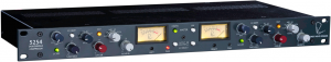
Rupert Neve Designs 5254: Dual Diode Bridge Compressor
Thank you for purchasing the Rupert Neve Designs 5254 Dual Diode Bridge Compressor. We hope you enjoy using this product as much as we have enjoyed designing and building it. The 5254 features custom Rupert Neve Designs transformer-coupled inputs and outputs, Class-A analog signal paths, and full-wave rectification in the compressor side chain.
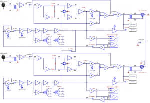
5254 Block Diagram
5254 Front Panel
![]()
HPF31-detent potentiometer that adjusts the side-chain high pass filter range from 20 Hz to 250 Hz
RATIO6-position rotary switch that adjusts the compressor ratio from 1.5:1 to 8:1
TIMING6-position rotary switch that adjusts the compressor attack and release times
VU METERIlluminated VU meter displays compressor output level or gain reduction
COMP INIlluminated push-button switch that engages both channels of the compressor
LINKPush-button switch that engages compressor stereo link mode
S/C INSERTPush-button switch that engages the S/C INSERT SEND and RETURN jacks on the rear panel for external side-chain processing
FASTIlluminated push-button switch that modifies the compressor time constants by 70% of their original values
S/C HPFIlluminated push-button switch that engages the compressor side-chain high pass filter
GAIN31-detent potentiometer that adjusts compressor make-up gain from -6 to +20 dB
PEAKPeak LED warns when signal levels are peaking 3dB below clip point
VU SELECTPush-button switch that toggles between metering the compressor output level (OUT) and gain reduction (IN)
THRESHOLD31-detent potentiometer that adjusts the compressor threshold from +20dBu to -25dBu
BLEND %31-detent potentiometer that controls the wet/dry mix of the compressed signal (wet) to the input signal (dry)
*Fully CW is compressed signal only
5254 Rear Panel
![]()
POWERAC Power inlet with power switch100-240 VAC50/60 Hz
LINE OUTPUTCustom Rupert Neve Designs transformer-coupled line output
S/C INSERT SENDCompressor side-chain insert SEND jack for connecting to the input of an external processor (ex: EQ)
LINE INPUTCustom Rupert Neve Designs transformer-coupled line input
S/C INSERT RETURNCompressor side-chain insert RETURN jack for connecting the output of an external processor (ex: EQ)
GND LIFTGround lift switch that lifts XLR LINE OUT Pin 1 from chassis ground
5254 Front-Panel Features
ThresholdThe THRESHOLD control is a 31-detent potentiometer that allows the user to adjust the point at which compression occurs, between -25dBu and +20dBu. Turning this control counter-clockwise will increase the amount of compression; turning it clockwise will decrease the amount of compression. If the input signal is lower than the set threshold, no compression will occur.
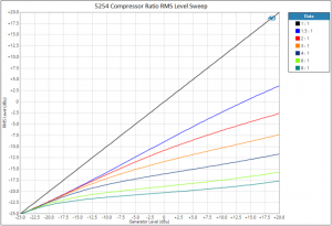
RatioThe RATIO control is a 6-position rotary switch that allows the user to set the slope of the compressor curve, ranging from 1.5:1 through 8:1. This ratio range allows the user to dial in a wide range of compression characteristics for their specific application.
TimingThe TIMING control is a 6-position rotary switch that allows the user to manipulate the attack and release times of the compressor simultaneously. Each TIMING setting has a different attack and release time range associated. Due to the nature of this topology, these time constants will adapt based on several factors: compression ratio, threshold, and source material. This allows the diode bridge compressor to remain flexible within a wide range of source material. We encourage the user to experiment with different combinations of RATIO, TIMING, and THRESHOLD settings to achieve the desired result.
GainThe GAIN control is a 31-detent potentiometer that allows the user to add make-up gain to compressed signal in order to match the compressed signal level with the input signal level. It is much easier to evaluate the effect of compression when these levels are matched for proper A-B comparison.
BlendThe BLEND control is a 31-detent potentiometer that allows the user to adjust the ratio of the compressed (wet) signal with the uncompressed (dry) signal to achieve parallel compression. Turning the BLEND control fully counter-clockwise shifts the mix toward the fully dry, uncompressed signal. Turning the BLEND control fully clockwise shifts the mix toward the fully wet, compressed signal.
FastThe FAST illuminated push-button switch modifies the attack and release times available on the TIMING control by 70% of their original values, effectively doubling the range of TIMING settings made available to the user.
LinkThe LINK switch engages stereo link mode. In stereo link mode, the compressor channel that is actively compressing the input signal the most will control the other channel in order to maintain a properly balanced stereo image.
Comp InThis illuminated push-button engages both channels of the compressor. This enables the user to AB the compressed and uncompressed signal while dialing in the proper compression characteristic for the given source material.
S/C HPFThe side-chain high-pass filter employs a 12dB/octave Sallen-Key filter that allows the user to control the amount of low frequency energy that hits the compressor side-chain. The 31-detent HPF potentiometer is continuously variable from 20Hz to 250Hz. The side-chain HPF is engaged when the S/C HPF push-button switch is set to the IN position.
5254 Front-Panel Features
S/C InsertThis push-button switch enables the S/C INSERT SEND and RETURN jacks on the rear-panel of the compressor. This allows the user to patch in additional external processing gear into the compressor side-chain (such as an external EQ). The side-chain insert level is -3dB referenced to the input level.
VU SelectThese push-button switches toggle the VU meter displays between compressor output level and compressor gain reduction. VU Reference Standard: 0VU = +4dBu
Peak LEDThe Peak LED will illuminate RED in order to warn the user that the output stage signal level is peaking 3dB below clip point.
VU Meter Endstop AdjustImportant: The recessed black adjusters below the VU meters come factory trimmed and should not need further adjustment. These adjusters allow for VU meter needle bottom endstop calibration (one tick mark below -20 VU).
5254 Rear-Panel Features
PowerIEC standard 3-pin grounded AC power inlet with power switch. 100-240VAC 50/60Hz input range with a maximum power consumption of 45W.
Line InputNeutrik XLR combo jack line input utilizing custom Rupert Neve Designs transformer-coupled, balanced inputs. Maximum input signal level is +26.7 dBu at 1kHz.
Line OutputNeutrik XLR jack line output utilizing custom Rupert Neve Designs transformer-coupled, balanced outputs. Maximum output signal level is +26.7 dBu at 1kHz.
S/C Insert Send and ReturnNeutrik TRS jacks utilized for compressor side-chain insert. These jacks are enabled by pressing the S/C INSERT push-button switches located on the front panel. A 1/4? TS cable should be used to make patches to and from external processing gear. The side-chain SEND jack should be connected to the INPUT of the external processor (EQ). The side-chain RETURN jack should be connected to the OUTPUT of the external processor.
S/C HPFThe side-chain high-pass filter employs a 12dB/octave Sallen-Key high pass filter that allows the user to control the amount of low frequency energy that hits the compressor side-chain. The 31-detent HPF potentiometer is continuously variable from 20Hz to 250Hz. The side-chain HPF is engaged when the S/C HPF push-button switch is set to the IN position.
Ground LiftThe ground lift switch can be used to interrupt a ground loop if encountered in the studio environment. In the LIFT position, Pin 1 of the XLR line outputs are disconnected from chassis ground.
5254 Specifications
XLR Line Input to XLR Line Output (Compressor Bypassed) ZSOURCE= 40 Ω BalancedInput Impedance 10 kΩOutput Impedance 40ΩMaximum Input Level (+4dBu Selected) +26.7 dBu typicalMaximum Output Level +26.7 dBu typicalNoise (22 Hz – 22 kHz BW) -104 dBu typicalFrequency Response (10 Hz to 120 kHz) +/- 0.25 dB typicalTHD+N @1 kHz @ Maximum Level (22 Hz – 22 kHz BW) 0.0008% typical
Compressor Noise Specifications ZSOURCE= 40 Ω BalancedNoise @ 0dB Make-Up Gain (22 Hz – 22 kHz BW) -84.5 dBu typicalNoise @ +20dB Make-Up Gain (22 Hz – 22 kHz BW) -64.5 dBu typical
Compressor Timing Specifications
Note: TIMING measurements represent the full range achievable between 1.5:1 and 8:1 ratio and FAST mode
FAST Attack 250µS – 2 mS // Release 100mS – 200mS typicalMF (MEDIUM FAST) Attack 1mS – 5mS // Release 100mS – 200mS typicalMED (MEDIUM) Attack 3mS – 18mS // Release 350mS – 700mS typicalMS (MEDIUM SLOW) Attack 5mS – 40mS // Release 600mS – 1S typicalSLOW Attack 10mS – 80 mS // Release 800mS – 1.5S typicalAUTO Attack 5mS – 40mS // Release T1 400-900mS, T2 1-2S typical
Product Dimensions (W x D x H) 19” (48.3 cm) x 8.25” (20.9 cm) x 1.65” (4.2 cm)
Shipping Dimensions (L x W x H) 24” (61 cm) x 13” (33 cm) x 4” (10.2 cm)
Shipping Weight 10 lbs. (4.5 kg)
PRODUCT WARRANTY
Rupert Neve Designs warrants this product to be free from defects in materials and workmanship for a period of three (3) years from date of purchase, and agrees to remedy any defect identified within such three year period by, at our option, repairing or replacing the product.
LIMITATIONS AND EXCLUSIONS
This warranty, and any other express or implied warranty, does not apply to any product which has been improperly installed, subjected to usage for which the product was not designed, misused or abused, damaged during shipping, damaged by any dry cell battery, or which has been altered or modified in any way. This warranty is extended to the original end user purchaser only. A purchase receipt or other satisfactory proof of date of original purchase is required before any warranty service will be performed. THIS EXPRESS, LIMITED WARRANTY IS IN LIEU OF ALL OTHER WARRANTIES, EXPRESS OR IMPLIED, TO THE EXTEND ALLOWED UNDER APPLICABLE STATE LAW. IN NO EVENT SHALL RUPERT NEVE DESIGNS BE LIABLE FOR ANY SPECIAL, INCIDENTAL, OR CONSEQUENTIAL DAMAGES RESULTING FROM THE USE OF THIS PRODUCT. Some states do not allow the exclusion or limitation of consequential damages or limitations on how long an implied warranty lasts, so this exclusion may not apply to you.
WARRANTY SERVICE
If you suspect a defect in this product, please call us at 512-847-3013 or contact our support staff ([email protected]) for troubleshooting. If it is determined that the device is malfunctioning, we will issue a Return Material Authorization and provide instructions for shipping the device to our service department.

Rupert Neve DesignsPO Box 1969Wimberley TX 78676www.rupertneve.comtel: +1 512-847-3013fax: +1 512-847-8869
775-00040 Rev B
References
[xyz-ips snippet=”download-snippet”]