![]()
MBCMaster Buss Converter
 Operations Manual
Important Safety Instructions
- Read these instructions.
- Keep these instructions.
- Heed all warnings.
- Follow all instructions.
- Do not use this apparatus near water.
- Clean only with a dry cloth.
- Do not block any ventilation openings. Install in accordance with the manufacturer’s instructions.
- Do not install near any heat sources such as radiators, heat registers, stoves, or other apparatus (including amplifiers) that produce heat.
- Do not defeat the safety purpose of the polarized or grounding-type plug. A polarized plug has two blades with one wider than the other.A grounding-type plug has two blades and a third grounding prong.The wide blade or the third prong are provided for your safety. If the provided plug does not fit into your outlet, consult an electrician forreplacement of the obsolete outlet.
- Protect the power cord from being walked on or pinched particularly at plugs, convenience receptacles, and the point where they exit from theapparatus.
- Only use attachments/accessories specified by the manufacturer.
- Use only with a cart, stand, tripod, bracket, or table specified by the manufacturer, or sold with the apparatus. When a cart is used, use cautionwhen moving the cart/apparatus combination to avoid injury from tip-over.

- Unplug this apparatus during lightning storms or when unused for long periods of time.
- Refer all servicing to qualified service personnel. Servicing is required when the apparatus has been damaged in any way, such as power-supply cord or plug is damaged, liquid has been spilled or objects have fallen into the apparatus, the apparatus has been exposed to rain or moisture, does not operate normally, or has been dropped.
- This apparatus shall not be exposed to dripping or splashing, and no object filled with liquids, such as vases or beer glasses, shall be placedon the apparatus.
- Do not overload wall outlets and extension cords as this can result in a risk of fire or electric shock.
- This apparatus has been designed with Class-I construction and must be connected to a main socket outlet with a protective earthing connection (the third grounding prong).
- This apparatus has been equipped with a rocker-style AC main power switch. This switch is located on the rear panel and should remain readily accessible to the user.
- The MAINS plug or an appliance coupler is used as the disconnect device, so the disconnect device shall remain readily operable.
CAUTION AVISRISK OF ELECTRIC SHOCK. DO NOT OPENRISQUE DE CHOC ELECTRIQUE. NE PAS OUVRIRCAUTION: TO REDUCE THE RISK OF ELECTRIC SHOCK DO NOT REMOVE COVER (OR BACK)NO USER-SERVICEABLE PARTS INSIDE. REFER SERVICING TO QUALIFIED PERSONNEL The lightning flash with an arrowhead symbol within an equilateral triangle is intended to alert the user to the presence of uninsulated “dangerous voltage” within the product’s enclosure, that may be of sufficient magnitude to constitute a risk of electric shock to persons.The exclamation point within an equilateral triangle is intended to alert the user of the presence of important operating and maintenance (servicing) instructions in the literature accompanying the appliance. - NOTE: This equipment has been tested and found to comply with the limits for a Class B digital device, pursuant to part 15 of the FCC Rules.These limits are designed to provide reasonable protection against harmful interference in a residential installation. This equipment generates, uses, and can radiate radio frequency energy and, if not installed and used in accordance with the instructions, may cause harmful interference to radio communications. However, there is no guarantee that interference will not occur in a particular installation.If this equipment does cause harmful interference to radio or television reception, which can be determined by turning the equipment off andon, the user is encouraged to try to correct the interference by one or more of the following measures:• Reorient or relocate the receiving antenna.• Increase the separation between the equipment and the receiver.• Connect the equipment into an outlet on a circuit different from that to which the receiver is connected.• Consult the dealer or an experienced radio/TV technician for help.CAUTION: Changes or modifications to this device not expressly approved by Rupert Neve Designs LLC, could void the user’s authority tooperate the equipment under FCC rules.
- This apparatus does not exceed the Class A/Class B (whichever is applicable) limits for radio noise emissions from digital apparatus as set out in the radio interference regulations of the Canadian Department of Communications.
- Exposure to extremely high noise levels may cause permanent hearing loss. Individuals vary considerably in susceptibility to noise-induced hearing loss, but nearly everyone will lose some hearing if exposed to sufficiently intense noise for a period of time. The U.S. Government’s Occupational Safety and Health Administration (OSHA) has specified the permissible noise level exposures shown in the following chart.According to OSHA, any exposure in excess of these permissible limits could result in some hearing loss. To ensure against potentially dangerous exposure to high sound pressure levels, it is recommended that all persons exposed to equipment capable of producing high sound pressure levels use hearing protectors while the equipment is in operation. Earplugs or protectors in the ear canals or over the ears must be worn when operating the equipment in order to prevent permanent hearing loss if exposure is in excess of the limits set forth here:
Duration, per day in hours Sound Level dBA, Slow Response Typical Example 8 90 Duo in a small club 6 92 4 95 Subway Train 3 97 2 100 Typical music via headphones 1.5 102 1 105 Siren at 10 m distance 0.5 110 0.25 or less 115 Loudest parts at a rock concert

WARNING — To reduce the risk of fire or electric shock, do not expose this apparatus to rain or moisture.
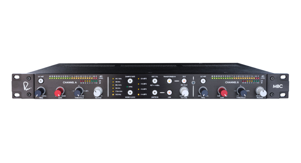
Rupert Neve Designs MBC: Master Buss ConverterThank you for purchasing the Rupert Neve Designs Master Buss Converter. We hope you enjoy using this product as much as we have enjoyed designing and building it. The MBC features Class-A analog signal paths, a stereo VCA limiter, and AKM Analog-to-Digital conversion.
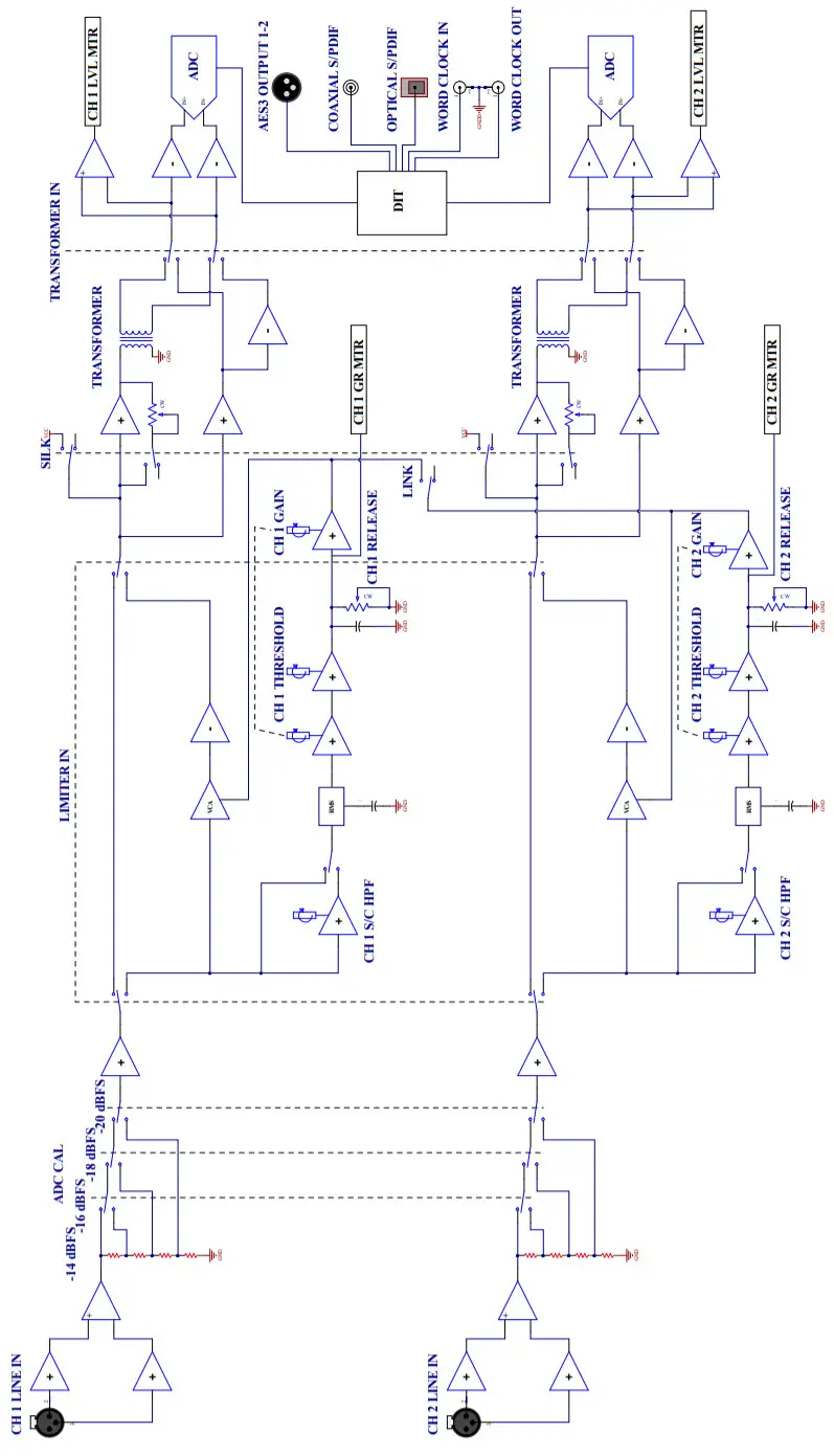
MBC Block Diagram
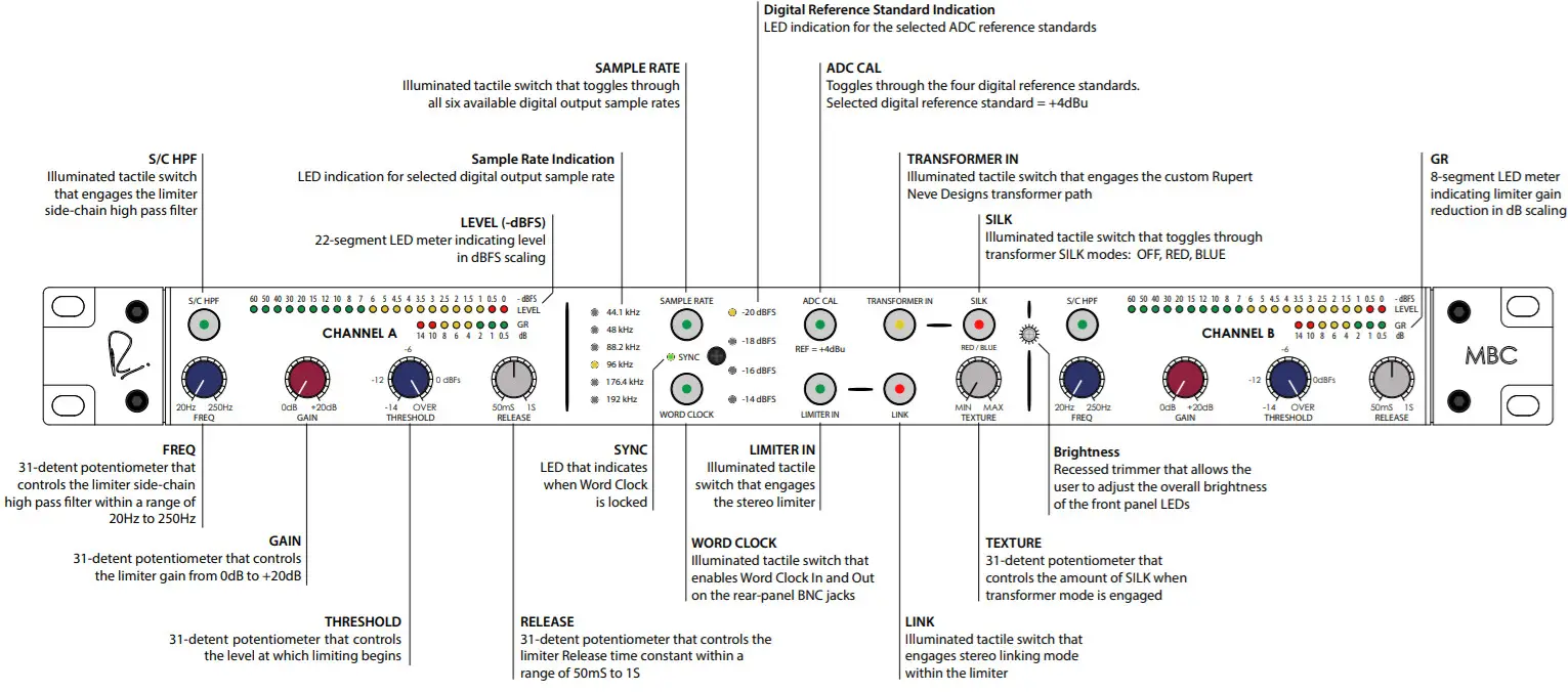
MBC Front Panel
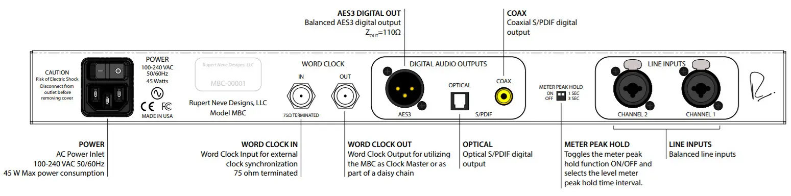
MBC Rear Panel
MBC Front-Panel Features
Sample Rate
This illuminated tactile switch toggles through the MBC’s available digital output sample rates: 44.1kHz 48 kHz, 88.2kHz, 96kHz, 176AkHz, and 192kHz at 24-bit depth resolution. In addition, there are six corresponding front-panel LEDs that illuminate when their corresponding sample rate is selected.
Sync
The SYNC LED will illuminate when Word Clock is enabled and a valid Word Clock signal is detected at the WORD CLOCK IN BNC on the MBC’s rear panel.
Word Clock
This illuminated tactile switch enables the WORD CLOCK IN and WORD CLOCK OUT BNC jacks on the MBC rear panel. When a valid word clock signal is present at the word clock input jack, the SYNC LED will illuminate, the sample rate LED status will update to reflect the incoming word clock rate, and a buffered version of the word clock input signal will be provided at the word clock output 8NC jack for word clock daisy-chaining.
ADC Calibration (ADC CAL)
This illuminated tactile switch toggles through the MBC’s available digital reference calibration standards: -14c1I3FS, -16dBFS, -18dBFS, and -20dBFS. Each of these digital levels is referenced to +4d8u in the analog domain. In addition, there are four corresponding LEDs that illuminate when their respective reference level is selected.
Transformer In
This illuminated tactile switch engages the custom Rupert Neve Designs inter-stage transformer within the MBC’s analog signal path. The transformer path is designed to add harmonic character and tonality to the audio path, while still maintaining wide bandwidth, low distortion, and high signal-to-noise ratio. If more color and transformer saturation is desired, the user can engage the SILK feature.
Silk
This illuminated tactile switch toggles through the available SILK transformer saturation modes: OFF, RED, and BLUE. Red Silk adds transformer saturation to the audio path with a high-frequency pre-emphasis. Blue Silk adds transformer saturation to the audio path with a low-frequency pre-emphasis.
Texture
This 31-detent potentiometer controls the amount of SILK transformer saturation added to the analog signal path when TRANSFORMER IN is selected.
Limiter In
This illuminated tactile switch engages both channels of the limiter. This enables the user to AB the compressedand uncompressed signal while dialing in the proper compression characteristic for the given source material.
Link
This illuminated tactile switch engages limiter stereo link mode. In stereo link mode, the limiter channel that is activelylimiting the input signal the most will control the other channel in order to maintain a properly balanced stereo image.
Side-chain High Pass Filter (S/C HPF)
The limiter side-chain has a fully-variable 31-detent potentiometer that controls the 12 dB/octave fallen-key high-pass filter. This allows the user to de-emphasize the amount of limiting that takes place on low-frequency energy in the source material. The full range of the limiter side-chain high-pass filter is 20Hz to 250Hz.
GainThe 31-detent limiter GAIN control allows the user to increase the gain of the input signal until it reaches the level at which the threshold is currently set. If gain is increased beyond the threshold level, the limiter output level will increase at the limiter’s fixed ratio of 10:1 (for every +10dB increase is input level, only +1dB increase in limiter output level).ThresholdThe 31-detent THRESHOLD potentiometer controls the level at which limiting begins in -dBFS scaling. The full range of the threshold control is from -14 dBFS (fully CCW) to OVER (fully CW). The OVER position allows the user to have the limiter engaged without incurring any limiting. This way, the user can more precisely control the point at which limiting occurs as they bring the limiter threshold down to the desired ceiling level below 0 dBFS.ReleaseThis 31-detent potentiometer controls the limiter RELEASE time within a range of 50mS (fully CCW) to 1S (fully CW). The limiter’s attack time is fixed at 500μS.
MBC Rear-Panel Features
Power
IEC standard 3-pin grounded AC power inlet with power switch. 100-240VAC 50/60Hz input range with a maximum power consumption of 45W.
Line Inputs
The MBC has two balanced inputs made available on Neutrik XLR Combo jacks. The input topology is designed to provide excellent Common Mode Rejection and a constant input impedance regardless of whether they are fed from a balanced or unbalanced source.
Digital Audio Outputs
The MBC has three available digital output connections: AES3 Balanced, Optical S/PDIF, and Coaxial S/PDIF. All three outputs can be connected simultaneously if needed. The digital output sample rates will follow the sample rate indicated on the MBC front panel.
Word Clock In
This 75 0 terminated Word Clock Input BNC jack is made available for synchronizing the MBC to an external Master Clock. When a valid Word Clock signal is connected and the front panel WORD CLOCK switch is selected, the MBC will sync to the incoming rate and adjust its digital outputs accordingly.
Word Clock Out
When the WORD CLOCK front-panel switch is enabled, the MBC will provide a buffered version of the Word Clock Input signal on the Word Clock Output BNC jack. If there is no valid Word Clock Input signal, but the WORD CLOCK front-panel switch is engaged, then the MBC will provide its own internal Master Clock at the Word Clock Output BNC jack. If the WORD CLOCK front-panel switch is not engaged, then there will be no Word Clock Output signal.
Meter Peak Hold
This dual dipswitch allows the user to adjust the MBC’s meter Peak Hold feature. The left switch turns the Peak Hold feature ON (Up) and OFF (Down), and the right switch toggles between a 15 (Up) and 35 (Down) peak hold time.
MBC Specifications
| XLR Line Input to AES3 Digital Output (Limiter Bypassed) | z SOURCE = 40 Ω Balanced |
| Input Impedance | 9.9 kΩ |
| Common Mode Rejection @ 1 kHz | 105 dB typical |
| Transformer-less Path | |
| Frequency Response (20 Hz to 70 kHz) | +/- 0.025 dB typical |
| THD+N @1 kHz @ -2 dBFS (10 Hz – 22 kHz BW) | 0.0009% typical |
| Noise (BW 10 Hz – 22 kHz) | -108 dBFS typical |
| Transformer Path | |
| Transformer Frequency Response (20 Hz to 70 kHz) | +/- 0.1 dB typical |
| THD+N @1 kHz @ -2 dBFS (10 Hz – 22 kHz BW) | 0.002% typical |
| Noise (BW 10 Hz – 22 kHz) | -114 dBFS typical |
| Limiter Specifications (Transformer-less Path Selected) | ZSOURCE= 40 Ω Balanced |
| Frequency Response (20 Hz to 70 kHz) | +/- 0.1 dB typical |
| Noise @ 0 dB Make-Up Gain (10 Hz – 22 kHz BW) | -107 dBFS typical |
| Noise @ +20 dB Make-Up Gain (10 Hz – 22 kHz BW) | -97 dBFS typical |
| Product Dimensions (W x D x H) | 19” (48.3 cm) x 9” (22.9 cm) x 1.65” (4.2 cm) |
| Shipping Dimensions (L x W x H) | 24” (61 cm) x 13” (33 cm) x 4” (10.2 cm) |
| Shipping Weight | 10 lbs. (4.5 kg) |
 report this ad
MBC Frequency Response – Transformer-less vs. Transformer (192kHz SR)
This page intentionally left blank
PRODUCT WARRANTY
Rupert Neve Designs warrants this product to be free from defects in materials and workmanship for a period of three (3) years from the date of purchase and agrees to remedy any defect identified within such three year period by, at our option, repairing or replacing the product.LIMITATIONS AND EXCLUSIONSThis warranty, and any other express or implied warranty, does not apply to any product which has been improperly installed, subjected to usage for which the product was not designed, misused or abused, damaged during shipping, damaged by any dry cell battery, or which has been altered or modified in any way. This warranty is extended to the original end-user purchaser only. A purchase receipt or other satisfactory proof of date of original purchase is required before any warranty service will be performed. THIS EXPRESS, LIMITED WARRANTY IS IN LIEU OF ALL OTHER WARRANTIES, EXPRESS OR IMPLIED, TO THE EXTEND ALLOWED UNDER APPLICABLE STATE LAW. IN NO EVENT SHALL RUPERT NEVE DESIGNS BE LIABLE FOR ANY SPECIAL, INCIDENTAL, OR CONSEQUENTIAL DAMAGES RESULTING FROM THE USE OF THIS PRODUCT. Some states do not allow the exclusion or limitation of consequential damages or limitations on how longan implied warranty lasts, so this exclusion may not apply to you.WARRANTY SERVICEIf you suspect a defect in this product, please call us at 512-847-3013 or contact our support staff ([email protected]) for troubleshooting. If it is determined that the device is malfunctioning, we will issue a Return Material Authorization and provide instructions for shipping the device to our service department.
Rupert Neve DesignsPO Box 1969Wimberley TX 78676www.rupertneve.comtel: +1 512-847-3013fax: +1 512-847-8869775-00039 Rev B
References
[xyz-ips snippet=”download-snippet”]