SALUS SmartPlug User Guide
Safety Instructions
Read these instructions carefully before installing and using the Z-Wave SmartPlug and keep this guide in a safe place for future reference.
- Verify compatibility with your home network before installation.
- Follow all instructions provided by the manufacturer of your home network regarding the addition of devices to your connected home system. An authorized, qualified installer may be required.
Salus accepts no responsibility for damage caused by not following these instructions.
Product Introduction
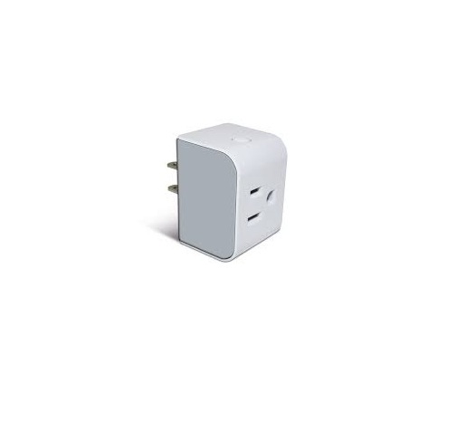
The Salus Z-Wave SmartPlug switch is a connected AC switch that is compatible with Z-Wave networks. This device provides ON/OFF control and measures the power/energy consumption of the attached AC appliance. Key features include:
- Quick and easy installation
- Support for Z-Wave connected home networks
- Support for loads up to 15Amps (resistive).
- SmartStart functionality using the QR code on the device.SmartStart enabled products can be added into a Z-Wave network by scanning the Z-Wave QR Code present on the product with a controller providing SmartStart inclusion. No further action is required and the SmartStart product will be added automatically within 10 minutes of being switched on in the network vicinity.
Compliance Note: This product can be operated in any Z-Wave network with other Z-Wave certified devices from other manufacturers. All AC powered nodes within the network will act as repeaters regardless of vendor to increase reliability of the network. act as signal repeaters regardless of manufacturer.
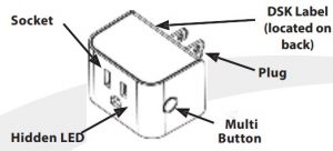
| Item | Description |
| Plug | NEMA 5-15 (Type B) plug. Compatible with US and Canadian 120VAC/15A electrical outlets |
| Socket | NEMA 5-15 (Type B) outlet. Compatible with US/Canadian 120VAC/15A electrical plugs |
| Multi Button | Multi-function user input button: Pair, Rejoin, Factory Defaults, and On/Off |
| Hidden LED | Red/Green LED status indicator |
Add (Include) a device to a network
- Refer to the instructions for your Z-Wave certified controller to add a device to the Z-Wave network.
- Locate the Device Specifi Key (DSK) label located on the back (plug side) of the SmartPlug. Scan QR code to obtain DSK.
- Plug the SmartPlug switch into an AC outlet at the desired location to account for any radio interference.
- Press the Multi Button once to initiate adding the device to the network.
Remove (Exclude) a device from a network
- Refer to the instructions for your Z-Wave certified controller to remove a device to the Z-Wave network.
- Press the Multi Button once to remove the switch from the network.
Using the Switch
Note: After being plugged in, there is a slight delay before the SmartPlug switch starts measuring energy and responding to the button or remote command
Turn Off/On
- Press the Multi Button to toggle the SmartPlug switch betweenOff and On.
Reset to Factory Defaults
- Press and hold the Multi Button for more than 10 seconds.The amber LED will be illuminated for 2 seconds while it searches for the network. Please use this procedure only when the network primary controller is missing or otherwise inoperable.
Power up without Network Red LED flashes 5 times in 0.5 sec. on/0.5 sec. of Power up with Network k Red LED flashes 5 times in 0.2 sec. on / 0.1 sec. of Relay is ON Green LED Relay is OFF Red LED Factory Reset Amber LED for 2 seconds Overcurrent Protection Flashing Green 0.2 sec on / 0.2 sec. of
Troubleshooting
Will Not Pair ·
- Radio interference is present at the desired location.
- Relocate the Z-Wave receiver,
- Select a different location for the switch, or
- Add a Z-Wave repeater to the system.
Loss of Connection After Pairing
- Make sure Z-Wave receiver is operating
- Radio environment may have changed
- Reset to factory defaults to search for a better path
- Apply radio interference solutions above.
No Appliance Power When Switch LED is On
- Make sure the attached appliance switch is on. ·
- Make sure the appliance can be controlled via the AC supply.
Note: Appliances with “soft” on/off buttons cannot be turned on by turning the AC supply ON.
Specifications
| Operating Conditions | 32°F to 104°F (0°C to 40°C) < 90% humidity (non-condensing) |
| Storage Conditions | -4°F to 185°F (-20°C to 85°C) < 90% humidity (non-condensing) |
| Protocols Supported | Z-Wave |
| RF Frequency | 908.42MHz, ISM band |
| Input | 120VAC +/-10%, 60 Hz |
| Maximum Switch Current | 15 Amp resistive |
| Dimensions (w x h x d) | Including Plug: 2.13” x 1.46” x 2.32” (54 x 37 x 59 mm) Not including plug: 2.13” x 1.46” x 1.49” (54 x 37 x 38mm) |
Basic Set Command
Basic Set (0x00) = Binary Switch Set (0x00)
Basic Set (0xFF) = Banary Switch Set (0xFF)
Basic Get = Binary Switch Get
Basic Report = Binary Switch Report
Z-Wave User Configuration
| Parameter | Description | Values | Size Byte) | Default |
| 1 | Status when powered up | 0 = Off 1 = On 2 = Status when last powered | 1 | 2 |
| 3 | Enable/ Disable for Group 2 & 3 | 0 = Group 2 & 3 disabled 1 = Group 2 enabled 2 = Group 3 enabled 3 = Group 2 & 3 enabled | 1 | 3 |
| 5 | Overvoltage Alarm (V) 1-200 = | Overvoltage Alarm threshold | 2 | 132 |
| 6 | Overcurrent Alarm (mA) | 1-15000 = Overcurrent Alarm threshold | 2 | 15000 |
| 21 | Power Change Report | 1 – 100 = % Power Change to Send Report | 1 | 10 |
| 22 | Overload Power Report | 1 – 1980 = 1 to 1980W | 2 | 1980 |
| 23 | Energy Report | 1 – 327 = 1 KWh to 327 KWh | 2 | 1 |
| 24 | Metering Report | 30 – 32767 = 30 – 32767 seconds to send report | 2 | 3600 |
| 25 | High Power Threshold | 0 = High Power Threshold disabled 1 – 32767 = High Power Threshold (Watts) | 2 | 1980 |
| 26 | Low Power Threshold | 0 = Low Power Threshold disabled 1 – 32767 = High Power Threshold (Watts) | 2 | 5 |
| 27 | Power Threshold Action | 1 = Power Threshold Action disabled 2 = Power High Threshold is enabled and send OFF to group 4 4 = Power High Threshold is enabled and send ON to group 4 8 = Power Low Threshold is enabled and send OFF to group 5 16 = Power Low Threshold is enabled and send ON to group 5 12 = 4 AND 8 | 1 | 12 |
Specific Configuration Role Type:Role Type: ·
- Always On Slave (AOS)
- Device Type: BINARY_SWITCH
- Supported security keys: S2Unauthenticated
Library: ·
- Generic Type: SWITCH_BINARY
- Specific Type: POWER_SWITCH_BINARY
Z-Wave Command Class Support
| ZWAVEPLUS_INFO V2 | CONFIGURATION V1 |
| TRANSPORT_ SERVICE V2 | BASIC V2 (Control and Support) |
| MANUFACTURER_SPECIFIC V2 | VERSION V3 – ASSOCIATION V2 |
| DEVICE_RESET_LOCALLY V1 | ASSOCIATION_GRP_INFO V3 |
| SECURITY_2 V1 | SUPERVISION V1 |
| POWERLEVEL v1 | FIRMWARE_UPDATE_META_DATA V4 |
| BINARY_SWITCH V1 | PROTECTION V2 |
| METER V4 | MULTI_CHANNEL_ASSOCIATION V3 |
| Notification V8 |
Events
| User Event | Notification Type | Notification Event |
| Overvoltage threshold is met | Power Management (0x08) | Overvoltage Detected(0x07) |
| Overcurrent threshold is met | Power Management (0x08) | Overcurrent Detected (0x06) |
| Overload threshold is met | Power Management (0x08) | Overload Detected (0x08) |
Association Group
Using association group, the Smart Plug is able to command or notify another device of a Z-Wave® network.
| Group | Group Name |
| 1 | Lifeline |
| 2 | Follow State |
| 3 | Follow Complementary State |
| 4 | Metering – High Threshold-Set On/Off |
| 5 | Metering – Low Threshold-Set On/Off |
Group 1 – Lifeline
Maximum number of devices in group: 5 This group is generally used to report information of the Smart Plug to the Main Controller of the network, including Meter, Binary Switch Report, Notification andDevice Reset Locally.Group 2 – Follow StateMaximum number of devices in group: 5 When the Smart Plug is switched ON (respectively OFF) using the local button, it will send ON (respectively OFF) command to the associated devices. No command is sent if the Smart Plug is switched ON or OFF wirelessly. This group is configurable through the parameter 3.Group 3 – Follow Complementary StateMaximum number of devices in group: 5 When the Smart Plug is switched ON (respectively OFF) using the local button, it will send OFF (respectively ON) command to the associated devices. No command is sent if the Smart Plug is switched ON or OFF wirelessly. This group isconfigurable through the parameter 3.Group 4 – Metering – High Threshold – Set On/OffMaximum number of devices in group: 5 When the Smart Plug reaches over the high threshold of power defined by the configuration parameter, it will send OFF or ON command to the associated devices. This group is configurable through the parameters25 and 27.Group 5 – Metering – Low Threshold – Set On/OffMaximum number of devices in group: 5 When the Smart Plug reaches below the low threshold of power defined by the configuration parameter, it will send OFF or ON command to the associated devices. This group is configurable through the parameters 26 and 27.
SALUS SmartPlug User Guide – SALUS SmartPlug User Guide –
References
[xyz-ips snippet=”download-snippet”]