SAMLEX Intelligent Battery Separator Owner’s Manual
Installation and user’s manual
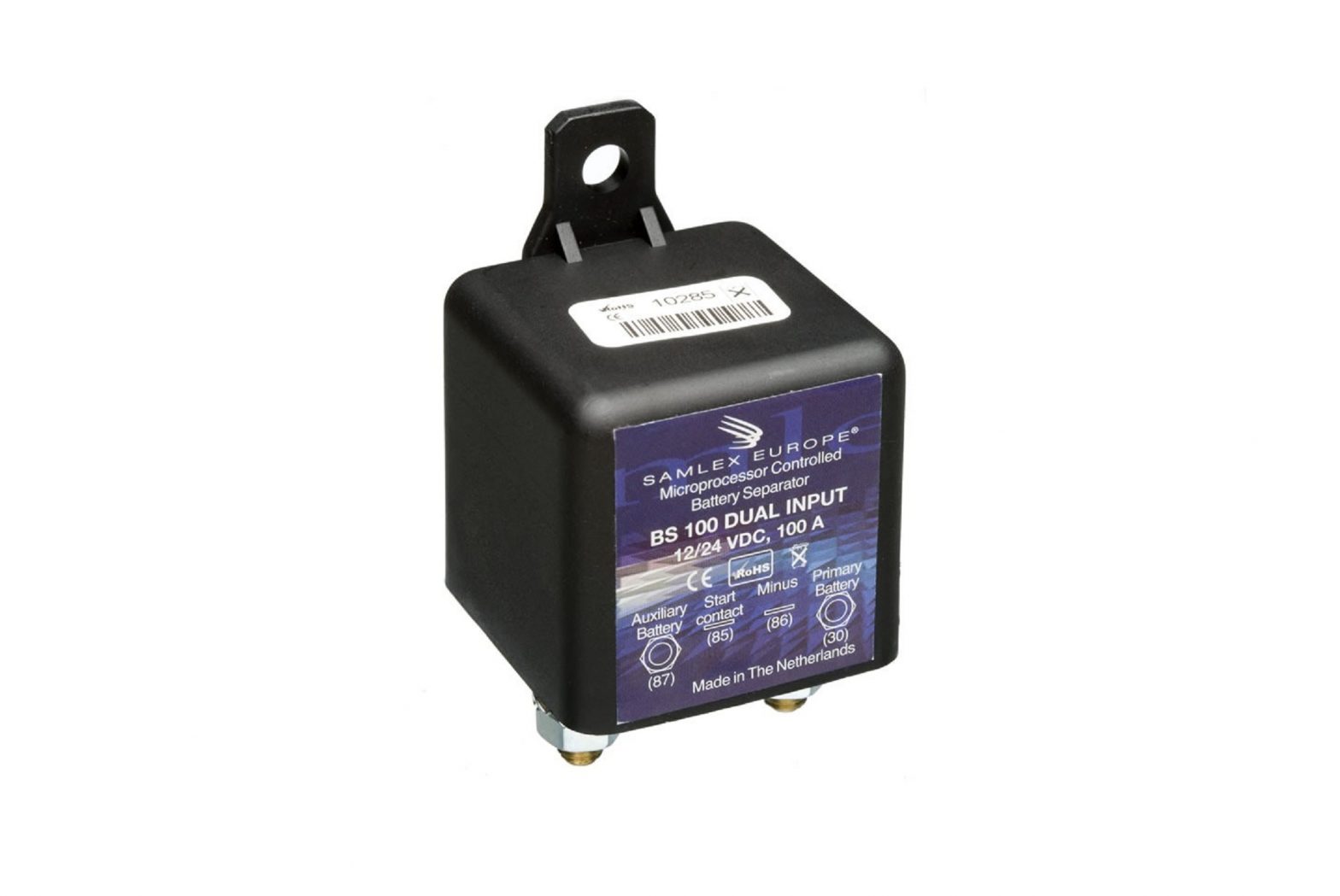
Description:The BS microprocessor controlled battery separator is used in multi-batteries systems like on boats, caravans and campers. It supervises the primary battery state of charge and therefore avoids starting problems. The BS can also be used as a voltage dependent switch. The working principle is the following: the BS lets the primary battery being recharged by the alternator until a voltage of 13.2V (26.4V) during at least 7 seconds is reached. Then the two batteries are put in parallel by the contact of the relay. The secondary users are normally connected to the auxiliary battery. The relay opens when the batteries voltage reaches 12.8V (25.6V) during at least 60 seconds. This way the starter battery remains charged. If a battery charger is connected to the auxiliary battery and this battery reaches a voltage of 13.2V (26.4V) during at least 7 seconds, the relay closes and charges at the same time the starter battery. This is an advantage if the vehicle remains stationary over a long period of time. If the battery charger is disconnected and the battery voltage reaches 12.8V (25.6V) during at least 60 seconds, then the BS separates again the two batteries.
Start assistance:The BS has an additional connection enabling an assistance to the starting. If the connection 85 (BS 100) or 86 (BS 140) is connected to the starter contact, the BS contact closes and this way the 2 batteries contribute to the engine start. Cautious when this function is used very high currents may go through the relay contact by the start of big engines. These high currents may damage the contact of the BS if they exceed its nominal current.
Voltage dependent switch:In some cases it is needed to have a powerful DC source supply but only when the engine is running. The BS allows also this kind of installations. It is sufficient to simply connect the primary battery to the connection 30, the system earth to the connection 86 (BS 100) or 85 (BS 140) and the positive of the equipment to supply to the connection 87. When the engine runs a voltage of 13,2V (26,4V) during at least 7 seconds is reached, the equipment is then powered thru the contact of the BS.
Protection against overvoltages:The BS has also a function enabling to protect the battery and the appliances that are connected to it against an overvoltage generated, for instance, by a defectuous alternator. As soon as a voltage higher than 16 V (32V) is detected, the contact of the BS opens immediately.
Installation:To implement the function « start assistance », a fuse protected connection has to be carried out between the connection 85 (BS 100) or 86 (BS 140) and the contact of the starter contact.A short-circuit between the positive and negative of the batteries can damage your system. Make sure that the connections are properly done!
Technical specifications:
Supply: Automatic detection 12/24 VMax. current: 100 A (BS 100) or 140 A (BS 140)Battery connection: M6Other connections: Faston 6,3 mmCable cross section: 25mm2Consumption OFF: 12V=1.5mA / 24V=1.5mAConsumption ON: 13.5V=360mA / 27V=160mAMinimum charge time: 60 secondsFast opening: < 11.8V (12V) / 23.6 (24V) after 4 seconds
Connections:30 Positive terminal of the primary battery (starter battery)85 Ignition switch (only if « start assistance » is needed) 86 for BS 14086 Negative terminal (Cautious this connection must always remain connected via a fuse of 3A) 85 for BS 14087 Positive terminal of the auxiliary battery (If the function « voltage dependent switch » is needed, connect the equipment positive here).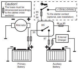
References
[xyz-ips snippet=”download-snippet”]