SAMSON AirLine AWXm Wireless System 7
Important Safety Information
- Read these instructions.
- Keep these instructions.
- Heed all warnings.
- Follow all instructions.
- Do not use this apparatus near water.
- Clean only with dry cloth.
- Do not block any ventilation openings. Install in accordance with the manufacturer’s instructions.
- Do not install near any heat sources such as radiators, heat registers, stoves, or other apparatus (including amplifiers) that produce heat.
- Do not defeat the safety purpose of the polarized or grounding-type plug. A polarized plug has two blades with one wider than the other. A grounding-type plug has two blades and a third grounding prong. The wide blade or the third prong are provided for your safety. If the provided plug does not fit into your outlet, consult an electrician for the replacement of the obsolete outlet.
- Protect the power cord from being walked on or pinched particularly at the plugs, convenience receptacles, and at the point where they exit from the apparatus.
- Only use attachments/accessories specified by the manufacturer.
- Use only with the cart, stand, tripod, bracket, or table specified by the manufacturer, or sold with the apparatus. When a cart is used, use caution when moving the cart/apparatus combination to avoid injury from tip-over.
- Unplug the apparatus during lightening storms, or when unused for long periods of time.
- Refer all servicing to qualified personnel. Service is required when the apparatus has been damaged in any way, such as power supply cord or plug is damaged, liquid has been spilled or objects have fallen into the apparatus has been exposed to rain or moisture, does not operate normally, or has been dropped.
- This appliance shall not be exposed to dripping or splashing water and that no object filled with liquid such as vases shall be placed on the apparatus.
- Caution-to prevent electrical shock, match wide blade plug wide slot fully insert.
- Please keep a good ventilation environment around the entire unit.
- The direct plug-in adapter is used as disconnect device, the disconnect device shall remain readily operable.
- Batteries (battery pack or batteries installed) shall not be exposed to excessive heat such as sunshine, fire or the like.
If you want to dispose this product, do not mix it with general household waste. There is a separate collection system for used electronic products in accordance with legislation that requires proper treatment, recovery and recycling.
Private household in the 28 member states of the EU, in Switzerland and Norway may return their used electronic products free of charge to designated collection facilities or to a retailer (if you purchase a similar new one).For Countries not mentioned above, please contact your local authorities for a correct method of disposal.By doing so you will ensure that your disposed product undergoes the necessary treatment, recovery and recycling and thus prevent potential negative effects on the environment and human health.
FCC Rules and Regulations
Samson wireless receivers are certified under FCC Rules part 15 and transmitters are certified under FCC Rules part 74. Licensing of Samson equipment is the user’s responsibility and licensability depends on the user’s classification, application and frequency selected.This device complies with Part 15 of the FCC rules Class B and RSS-210 of Industry & Science Canada.Operation is subject to the following two conditions:
(1) This device must not cause harmful interference, and(2) This device must accept any interference received including interference that may cause undesired operation. Suitable for home or office use.
NOTE: This equipment has been tested and found to comply with the limits for a Class B digital device, pursuant to Part 15 of the FCC Rules. These limits are designed to provide reasonable protection against harmful interference in a residential installation. This equipment generates, uses and can radiate radio frequency energy and, if not installed and used in accordance with the instructions, may cause harmful interference to radio communications. However, there is no guarantee that interference will not occur in a particular installation. If this equipment does cause harmful interference to radio or television reception, which can be determined by turning the equipment off and on, the user is encouraged to try to correct the interference by one or more of the following measures:
• Reorient or relocate the receiving antenna.• Increase the separation between the equipment and receiver.• Connect the equipment into an outlet on a circuit different from that to which the receiver is connected.• Consult the dealer or an experienced Radio/TV technician for help.
WARNING: Changes or modifications not expressly approved by the party responsible for compliance could void the user’s authority to operate the equipment.This equipment is intended for use in wireless microphone applications.Equipment is intended for sale in: AT, BE, CH, CY, CZ*, DK, EE, FI*, FR*, DE*, GR*, HU, IE, IS, IT, LV, LT*, LU, MT*, NL, NO*, PL* PT, RO, SK, SI, ES, SE, UK*Subject to license. Please contact your national frequency authority for information on available legal use in your area. Any changes or modifications not expressly approved by Samson Technologies Corp. could void your authority to operate the equipment.Hereby, Samson Technologies Corp., declares that this AR99m and ATX is in compliancewith the essential requirements and other relevant provisions of Directive 2014/53/EU. The declaration of conformity may be consulted at:http://www.samsontech.com/site_media/support/manuals/AirLineATXm_ATX_DOC.pdf
Introduction
Welcome to Samson AirLine, the original micro-wireless microphone systems. Wireless microphone and instrument systems were originally developed to eliminate cables, providing unparalleled freedom of movement. AirLine ATX takes this concept to a new level with frequency agile transmitters and micro receiver, providing a completely “hassle-free” user experience.
Designed to be an extension of your instrument rather than a separate component, the ATX Wireless Transmitter clips directly to your instrument bell with no cable necessary and lets you rule the stage with confidence. It provides up to 8 hours of continuous use with the internal lithium ion rechargeable battery.
The system includes the HM60 condenser microphone with 3-point halo isolation mount to minimize any noise caused by mechanical vibration. The mic capsule offers a supercardioid pickup pattern that handles up to 125dB SPL, ideal for handling the sudden attack of wind instruments. The HM60 also offers an 8.5” adjustable gooseneck (with P3 connector) for optimal mic placement in front of your instrument’s bell.
Offering frequency-agile UHF operation, the micro-sized True RF Diversity AR99m receiver provides 100 available channels to secure reliable wireless performance. The receiver provides easy setup with 1-touch scan which analyzes and selects the clearest operating channel, infrared set to pair the transmitter with the receiver, and versatile output connections (XLR, 1/4” and 1/8”). An included USB port can be used to charge the ATX transmitter or integrate a Samson XPD Series wireless system (sold separately) to make it a dual-receiver.
In these pages, you’ll find a detailed description of the features of the AirLine AWXm System, as well as step-by-step instructions for its setup and use. If your wireless system was purchased in the United States, you’ll also find a registration card enclosed—don’t forget to follow the instructions so that you can receive online technical support and so that we can send you updated information about this and other Samson products in the future. Also, be sure to check out our website www.samsontech.com for complete information about our full product line.
We recommend you keep the following records for reference, as well as a copy of your sales receipt:Receiver Serial number: _________________________________________Transmitter Serial number: ______________________________________Date of purchase: ______________________________________________
If you have any questions or comments regarding the AirLine AWXm system or any other products from Samson, do no hesitate to contact us at [email protected].With proper care and maintenance, your AirLine AWXm System will operate trouble-free for many years. Should your AirLine AWXm system ever require servicing, a Return Authorization (RA) number must be obtained before shipping your unit to Samson. Without this number, the unit will not be accepted. Please visit www.samsontech.com/ra for an RA number prior to shipping your unit. Please retain the original packing materials and, if possible, return the unit in its original carton. If your AirLine AWXm system was purchased outside of the United States, contact your local distributor for warranty details and service information.
Quick Start
In order for your wireless system to work correctly, both the receiver and transmitter must be set to the same channel. Follow this basic procedure for setting up and using your AirLine AWXm Wireless System:
- Physically place the AR99m receiver where it will be used, and extend the antennas vertically. The general rule of thumb is to maintain “line of sight” between the receiver and transmitter so that the person using or wearing the transmitter can see the receiver.

- Ensure that the ATX transmitter is fully charged (see section Charging the ATX Transmitter).
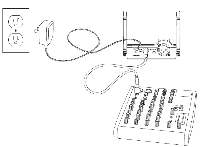
- With the AR99m powered off, connect the included power adapter.
- With your amplifier or mixer off and volume control all the way down, connect the AR99m receiver output jack to the mic or line level input of a mixer or amplifier using the balanced XLR output or unbalanced 1/4” or 1/8” line level outputs. Turn the VOLUME knob on the AR99m clockwise to turn its power on, but keep the level low.
- Press and hold the SET button on the front of the AR99m receiver to scan for an available channel. Once the optimal channel is selected the receiver will enter IR Set mode.
- Turn on the power to the ATX transmitter by pressing and holding the Power button for 3 seconds; the indicator LED will light yellow when the button is pressed and turns green when released and the ATX is powered on.
- Position the ATX transmitter about 6-12” (15-30 cm) from the front of the AR99m with the transmitter’s IR window facing the IR transmitter on the front panel of the AR99m receiver
- When the transmission is complete, the AR99m will receive RF signal and the tone key from the transmitter. The RF meter on the AR99m will light indicating that it is receiving wireless signal from the transmitter.Note: The ATX will only accept infrared transmission from the receiver for the first 10 seconds after the ATX is powered on. If you need to change the operating channel, the ATX must be first powered off, then powered on again to receive the new channel.
- Plug the HM60 microphone into the ATX transmitter.
- Turn on your connected amplifier or mixer, but keep the volume all the way down. Set the Volume knob on the AR99m fully clockwise. This is unity gain. Play your instrument at a normal performance level. Slowly raise the volume of your amplifier or mixer until the desired level is reached.
- Walk around the performance area to ensure the coverage is consistent throughout. If you find the system has noticeable dropouts, reduced overall working range, or unexpected noise bursts, change the operating channel of the system using the steps above.
- When using multiple systems, each system must be set to a different operating channel. Follow these steps to set each receiver and transmitter to the optimal channel.
Positioning the HM60 Wind Instrument Mic
When positioning the HM60 wind instrument microphone, there are some general rules that you should follow. Always position the microphone as close to the sound source as possible. This is easy with the HM60 since the integrated gooseneck guarantees the mic element is close to the source. Also, keep in mind that in order to minimize feedback problems you want to position the microphone, (and if necessary yourself), behind the main PA speakers. Be aware of a phenomenon called the proximity effect, which causes a noticeable increase in low frequencies (bass response) when a microphone is close to the audio source. This means that by making slight adjustments to the distance of the mic element, you can get a change in the tonal quality of your sound. Keep in mind that your sound is as personal as your playing style, therefore, you may find changing the microphone position gets you just the sound you looking for. As with everything, experience is the best teacher, so plug in and turn up and listen.Here are some starting points to help you along the way.Saxophone – Use the built-in clip to attach the ATX transmitter to the bell of the instrument and position the HM60 mic about 1” to 2” from the center of the bell. You can move the mic out a little to get some extra edginess, or closer for some extra warmth.Trumpet – Use the built-in clip to attach the ATX transmitter to the bottom of the bell on the instrument. Aim the HM60 microphone towards the center of the bell, but since the trumpet is capable of producing some of the highest SPL levels, start with the mic element positioned away from the bell. Try bringing the microphone element in closer to the bell for better isolation and more low-frequency response.Trombone – Attach the ATX clip to the bottom of the bell and position the HM60 microphone directly into the center. In this position, you will get the maximum isolation with full frequency response.
Charging the ATX Transmitter
- With the AR99m powered off, connect the included power adapter.
- Insert the magnetic power cable to the AR99m USB Port (or any 5-volt DC adapter that has a USB port).
- Turn the VOLUME knob on the AR99m clockwise to turn its power on.
- Place the ATX transmitter on a flat surface.
- Attach the magnetic connector to the gold contact power port on the bottom of the ATX transmitter. The cable attaches to the port magnetically.The magnetic connector is keyed so it will only connect in one direction.Note: Transmission is disabled during charging.
- Look at the indicator light on the ATX transmitter to determine when the transmitter has finished charging. When the light is flashing red, the ATX is charging. When the red light stops flashing it indicates that the ATX is fully charged.
- Disconnect the magnetic power cable from the ATX when the unit is fully charged.If you notice your ATX battery life is becoming shorter after a full charge, you can order a user replaceable battery from your local Samson distributor.
- Completely charge the batteries before first use
- Fully charge the battery before it will be used.
- After the battery is charged, unplug the charger from the outlet.
- The optimal temperature range for using and storing the battery is 50°F -86°F (30°C – 50°C). The battery performance and operation may decrease in temperatures below 50°F (30°C).
A warning that batteries (battery pack or batteries installed) shall not be exposed to excessive heat such as sunshine, fire or the like.CAUTION: Danger of explosion if battery is incorrectly replaced. Replace only with the same or equivalent type. Attention should be drawn to the environmental aspects of battery disposal
ATX Transmitter Callouts
![]()
- Power/Mute Button – Press and hold for 3 seconds to turn the unit on or off. A quick press and release will mute or unmute the transmitter when the transmitter is on.
- Status Indicator – This LED displays the operation mode, low battery and recharge status of the transmitter. The chart below defines the LED colors for each function.
- Volume +/– Buttons – Press and hold either Volume button to adjust the volume. Pressing the + or – button increases or decrease the level by one step with each push of the button. There is a total 9 volume levels. The Status Indicator light will flash faster for each increased step and slower for each decrease.
- IR Lens – This window is used to capture the infrared signal sent from the receiver during the IR SET to channelize the transmitter. The IR Lens is only active for the first 10 seconds when the transmitter is powered on.
- Charging Connector – Connect the supplied magnetic charging cable to this sealed, gold contact charging connector to recharge the internal lithium ion battery. The ATX can be recharged by connecting the cable to the AR99m receiver as well as to a USB connector on a computer USB port, or any 5-volt DC adapter that has a USB output.
- Input Connector – Connect the HM60 microphone via the mini-XLR connector.
- Spring Clip – Use this clip to fasten the ATX transmitter to an instrument bell.
AR99m Receiver Features
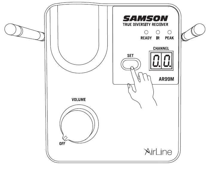
- Antennas – The antenna mountings allow full rotation for optimum placement. In normal operation, both antennas should be placed in a vertical position. Both antennas can be folded inward for convenience when transporting the AR99m.
- SET Button – Press this button to scan through the receiver’s 100 operating channels to find the optimal channel for performance. Once the scan is complete, the AR99m will enter IR Set modeand send the selected channel to the transmitter.
- LED Display – The two digit, 7-segment LED display shows the receiver’s current operating channel.
- READY Indicator – This indicator lights green when the AR99m is receiving RF signal and the system is ready to use.
- IR Transmitter – During “IR SET” infrared light is used to set the transmitter channel.
- PEAK Indicator – This indicator lights red when the transmitted audio signal is overloaded.
- VOLUME / Power Control – This rotary knob controls the level of the receiver output and powers the AR99m on and off. Turn the control clockwise to turn the system on. Turn the knob counterclockwise until it clicks to turn the system off.
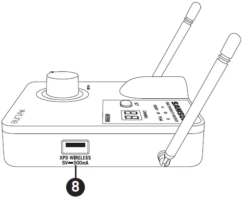
- USB Port – This USB port provides 5V 200mA of power which can be used to charge the ATX transmitter (AR99m only passes power to the USB port when the power is ON). It can also be used to connect an optional Samson XPD USBDigital Wireless receiver to this input, turning the AR99m into a dual wireless system.
AR99m Receiver Features Rear Panel
- DC Input – Connect the supplied power adapter here.WARNING: Do not substitute any other kind of power adapter. Doing so can cause severe damage to the AR99m and will void your warranty.
- UNBALANCED OUTPUTS – Use these unbalanced 1/4” and 1/8” jacks when connecting the AR99m to consumer (-10 dBV) audio equipment. Wiring is as follows: tip hot, sleeve ground.
- BALANCED OUTPUT – Use this electronically balanced low impedance (600 Ohm) XLR jack when connecting the AR99m to professional (+4 dBu) audio equipment. Pin wiring is as follows: Pin 1 ground, Pin 2 high (hot), and Pin 3 low (cold).
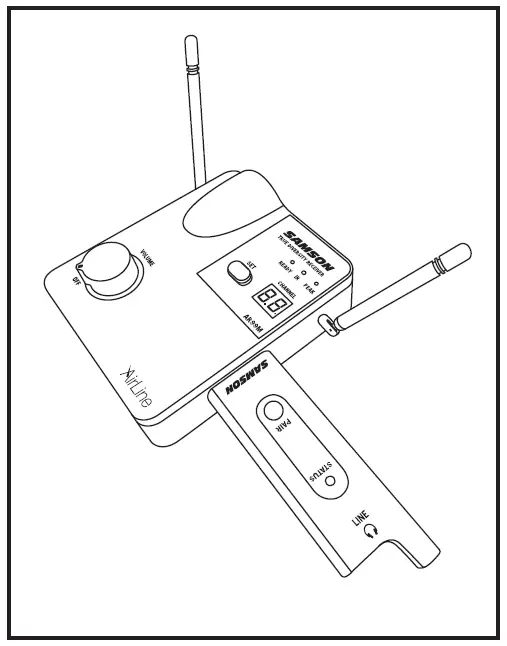
Connecting XPD Wireless
- Plug the XPD USB receiver into the USB jack on the side of the AR99m receiver.
- Place a fresh set of AA (LR6) batteries in the transmitter battery holder, taking care to observe the polarity markings.
- Turn the AR99m receiver on by rotating the VOLUME control clockwise. The AR99m VOLUME control will affect the mix of the ATX and XPD transmitters.
- Turn on the power to the XPD transmitter by pressing and holding Power switch; the indicator LED will light amber.
- If the transmitter and receiver have not been previously paired, press and hold the button on the XPD receiver for >5 seconds, until it begins to flash. Press and continue to hold the Power button on the transmitter until the LED indicators on both units light steady, indicating that the receiver and transmitter are paired and ready for operation.
- Speak or sing into the microphone at a normal performance level and raise the AR99m VOLUME control until the desired level is reached.
- To balance the level between the ATX and XPD transmitter, use the supplied screwdriver to adjust the Gain control inside the XPD battery compartment.If you hear distortion from the XPD transmitter turn down the Gain. Conversely, if you hear a weak, noisy signal at the desired volume level, turn the Gain control in the XPD transmitter slowly clockwise until the signal reaches an acceptable level.
 If you hear distortion from the XPD transmitter turn down the Gain. Conversely, if you hear a weak, noisy signal at the desired volume level, turn the Gain control in the XPD transmitter slowly clockwise until the signal reaches an acceptable level.
Specifications
System
Working Range: 300′ (100m) line of sightAudio Frequency Response: 50 Hz – 15 kHzT.H.D. (Overall): <1% (@AF 1 kHz, RF 46 dBu)Dynamic Range: > 100 dB A-weightedSignal to Noise: > 95 dBOperating Temperature: –10°C (14°F) to +60°C (+140°F)Tone Key Frequency: 35 kHz
Operating Bands and Frequency Ranges
| Band | Frequency Range |
| Kª | 470–494 MHz |
| Dª | 542–566 MHz |
| IL* | 794–806 MHz |
| B* | 806–810 MHz |
| G* | 863–865 MHz |
* Not for use in the USA and Canada.
European Frequency Operation
Note: This equipment is intended for professional musical and similar applications, and may be capable of operating on some frequencies not authorized in your region. Please contact your national authority to obtain information on authorized frequencies for wireless microphone products in your region.
| Band | Frequency Range | EU Country Codes | Note |
| Kª | 470–494 MHz | AT, BE, BG, CY, CZ, DK, EE, FI, FR, DE,
GR, HU, IS, IE, IT, LV, LT, LU, MT, NL, NO, PL, PT, RO, SK, SI, ES, SE, CH, UK |
|
| D** | 542–566 MHz | ||
| IL** | 794–806 MHz | For use in Israel | |
| B** | 806–810 MHz | For use in Japan | |
| G | 863–865 MHz | AT, BE, BG, CY, CZ, DK, EE, FI, FR, DE,
GR, HU, IS, IE, IT, LV, LT, LU, MT, NL, NO, PL, PT, RO, SK, SI, ES, SE, CH, UK |
License Free |
 report this ad
** Not for use in the EU.ª Licensing: Note that a ministerial license to operate this equipment may be required in certain areas. Consult your national authority for possible requirements. Licensing of Samson wireless microphone equipment is the user’s responsibility, and licensability depends on the user’s classification and application, and on the selected frequency.
[xyz-ips snippet=”download-snippet”]