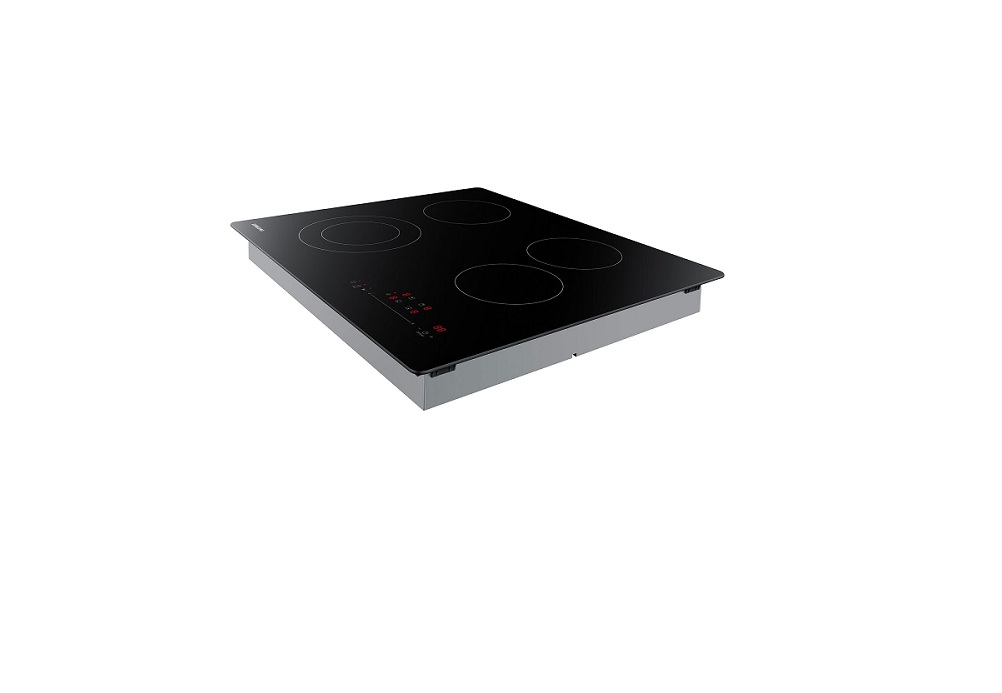
SAMSUNG Electric Cooktop Instruction Manual
Important Safety Information
For your safety
- For Personal Safety, remove house fuse or open circuit breaker before beginning installation. Failure to do so could result in serious injury or death.
- Be sure your cooktop is installed properly by a qualified installer or service technician.
- To eliminate the risk of burns or fire due to reaching over heated surface elements, cabinet storage located above the surface units should be avoided. If cabinet storage space is necessary, the risk can be reduced by installing a range hood that projects horizontally a minimum of 5″ beyond the bottom of the cabinets. Cabinet installation above the cooktop may be no deeper than 13″.
- Make sure the cabinets and wall coverings around the cooktop can withstand the temperatures (up to 194 °F) generated by the cooktop.
- The cooktop should be easy to reach and illuminated by natural light during the day.
- Always disconnect the electrical service to the cooktop before repairing or servicing the cooktop. This can be done by disconnecting the fuse or circuit breaker. Failure to do this could result in a dangerous or fatal shock. Know where your main disconnect switch is located. If you do not know, have your electrician show you.
Installation Requirements
For your SafetyThis appliance must be supplied with the proper voltage and frequency, and connected to an individual, properly grounded branch circuit. We recommend you have the electrical wiring and hookup of your cooktop connected by a qualified electrician. After installation, have the electrician show you where your main cooktop disconnect is located. The cooktop conduit wiring is approved for copper wire connection only, and if you have aluminum house wiring, you must use special UL approved connectors for joining copper to aluminum.![]() WARNINGIf the information in this manual is not followed exactly, a fire or electrical shock may result causing property damage, personal injury, or death.
WARNINGIf the information in this manual is not followed exactly, a fire or electrical shock may result causing property damage, personal injury, or death.![]() WARNINGBefore beginning the installation, switch the power off at the service panel and lock the service disconnecting switch to prevent power from being switched on accidentally. When the service disconnecting switch cannot be locked, securely fasten a prominent warning device, such as a tag, to the service panel.
WARNINGBefore beginning the installation, switch the power off at the service panel and lock the service disconnecting switch to prevent power from being switched on accidentally. When the service disconnecting switch cannot be locked, securely fasten a prominent warning device, such as a tag, to the service panel.![]() WARNINGThis appliance must be properly grounded.
WARNINGThis appliance must be properly grounded.
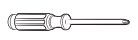
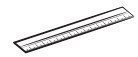
Tool and PartsTools you will need
- Pencil

- Phillips Head Screwdriver
- Ruler or Straightedge
- Safety Glasses
- Saber Saw
- 1/2″ Drill Bit & Electric or Hand Drill

Parts Needed
- A UL listed or CSA approved connector for ½” (1.3 cm) diameter conduit.
- UL listed wire connectors Check local codes. Check existing electrical supply. See the “Electrical requirements” section. It is recommended that all electrical connections be made by a licensed, qualified electrical installer.
Parts Included
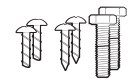
- 6 screw
- (M4L10 2 ea, M4L16 2 ea, M4L75 2 ea)Bracket Guide: 2 ea
Installation Requirements
Location requirementsIMPORTANT: Observe all governing codes and ordinances.
- Cabinet opening dimensions that are shown must be used. Recessed installation area must provide complete enclosure around the recessed portion of the cooktop.
- Grounded electrical supply is required. See “Electrical Requirements” section.
![]() NOTE:It is recommended to install the Junction box on right side of the cabinet.If installing the junction box near the left side, make sure the junction box does not interfere with the cooktop (by concealing the junction box inside the wall).IMPORTANT: To avoid damage to your cabinets, check with your builder or cabinet supplier to make sure that the materials used will not discolor, delaminate or sustain other damage. This cooktop has been designed in accordance with the requirements of UL and CSA International and complies with the maximum allowable wood cabinet temperatures of 194 °F (90 °C).
NOTE:It is recommended to install the Junction box on right side of the cabinet.If installing the junction box near the left side, make sure the junction box does not interfere with the cooktop (by concealing the junction box inside the wall).IMPORTANT: To avoid damage to your cabinets, check with your builder or cabinet supplier to make sure that the materials used will not discolor, delaminate or sustain other damage. This cooktop has been designed in accordance with the requirements of UL and CSA International and complies with the maximum allowable wood cabinet temperatures of 194 °F (90 °C).
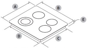
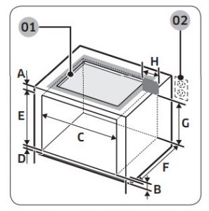
Product Dimensions
|
Cabinet |
Dimension |
|
|
A |
Frame Depth | 207/16″ (520 mm) |
|
B |
Frame Width | 23⅝” (600 mm) |
|
C |
Case Depth | 187/16″ (468 mm) |
|
D |
Case Width | 219/16″ (548 mm) |
|
E |
Conduit Case Height | 3⅜” (86 mm) |
|
F |
Case Height | 2⅜” (60 mm) |
|
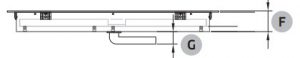
G |
Conduit Height | 1″ (26 mm) |
IMPORTANT:If installing a range hood or microwave hood combination above the cooktop, follow the range hood or microwave hood combination installation instructions for dimensions and clearance above the cooktop surface.
|
Dimension |
|
|
A |
22″ – 22⅛” (558 mm – 562 mm) |
|
B |
1813/16″ – 19″ (478 mm – 482 mm) |
|
C |
Cut area and back wall of Cooktop – minimum 1⅛” (28 mm) |
|
D |
Front edge of cut area and front edge of worktop – minimum 1½” (38 mm) |
|
E |
Flammable surface closest to the Cooktop (left/right) – minimum 1″ (26 mm) |
|
F |
Junction box or outlet from cabinet right – maximum 10″ (254 mm) |
|
G |
Junction box or outlet from cabinet bottom – minimum Junction box or outlet 15″ (381 mm) |
|
H |
Insulating board 2″ (50.9 mm) minimum from bottom of Cooktop |
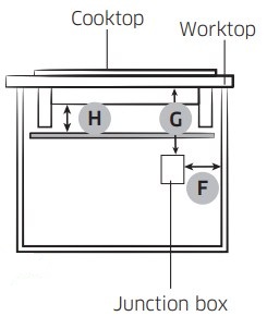
Single Oven Under counter
- See manual of built-in oven installation for complete installation instructions. See label on top of approved built-in oven models.
- Refer installation Manual of oven.
|
Dimension |
|
|
A |
Minimum 3¾” (95 mm) |
|
B |
4″ (101 mm) |
|
C |
Minimum 221/16″ / Maximum 22¼” (Minimum 560 mm / Maximum 565 mm) |
|
D |
Minimum 1″/ Maximum 1¼” (Minimum 25 mm / Maximum 32 mm) |
|
E |
Minimum 23¼”/ Maximum 23½” (Minimum 590 mm / Maximum 596 mm) |
|
F |
22¼” (565 mm) |
|
G |
Minimum 22¼” (Minimum 565 mm) |
|
H |
Maximum 9½” (Maximum 241 mm) – Junction Box |
Make sure the wall coverings, countertop and cabinets around the cooktop can withstand heat (up to 194 °F) generated by cooktop.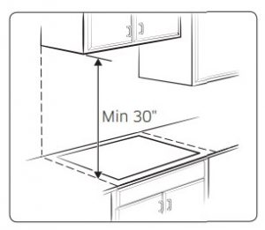
![]() NOTE If cabinet has a drawer, a minimum 127 mm (5″) depth clearance from the bottom of cooktop to top of the drawer (or other obstruction) in base cabinet is required.IMPORTANT: The junction box must be located where it will allow considerable slack in the conduit for serviceability.
NOTE If cabinet has a drawer, a minimum 127 mm (5″) depth clearance from the bottom of cooktop to top of the drawer (or other obstruction) in base cabinet is required.IMPORTANT: The junction box must be located where it will allow considerable slack in the conduit for serviceability.
Electrical requirements
![]() WARNINGElectrical Shock HazardDisconnect power before servicing. Use 8 gauge solid copper wire. Electrically ground cooktop. Label Refer to the label on the bottom of the cooktop for power requirements and model information. Failure to follow these instructions can result in death, fire, or electrical shock. If codes permit and a separate ground wire is used, it is recommended that a qualified electrical installer determine that the ground path and the wire gauge are in accordance with local codes. Check with a qualified electrical installer if you are not sure the cooktop is properly grounded.
WARNINGElectrical Shock HazardDisconnect power before servicing. Use 8 gauge solid copper wire. Electrically ground cooktop. Label Refer to the label on the bottom of the cooktop for power requirements and model information. Failure to follow these instructions can result in death, fire, or electrical shock. If codes permit and a separate ground wire is used, it is recommended that a qualified electrical installer determine that the ground path and the wire gauge are in accordance with local codes. Check with a qualified electrical installer if you are not sure the cooktop is properly grounded. Refer to the label on the bottom of the cooktop for power requirements and model information.
This cooktop must be connected to a grounded metal, permanent wiring system. Be sure that the electrical connection and wire size are adequate and in conformance with the National Electrical Code, ANSI/NFPA 70-latest edition or CSA Standards C22. 1-94, Canadian Electrical Code, Part 1 and C22.2 No. O-M91-latest edition, and all local codes and ordinances. A copy of the above code standards can be obtained from:
National Fire Protection Association 1 Batterymarch Park Quincy,MA 02169-7471 CSA International 8501 East Pleasant Valley Road Cleveland, OH 44131-5575
Before you make the electrical connection:To properly install your cooktop, you must determine the type of electrical connection you will be using and follow the instructions provided for it here.
- A 3-wire or 4-wire, single phase, 208 or 240 volt AC, 60-Hz, power supply isrequired on a dedicated double pole circuit breaker of at least 30 amps. NOTE
- The cooktop is rated 240 volt. Some models have a neutral (white) wire. ·
- The cooktop should be connected directly to the junction box through flexible, armored or nonmetallic sheathed, copper cable. The flexible, armored cable extending from the fuse box or circuit breaker box should be connected directly to the junction box.
- Locate the junction box to allow as much slack as possible between the junction box and the cooktop so that the cooktop can be moved if servicing becomes necessary in the future.
- Do not cut the conduit. Use the length of conduit provided.
- A UL listed or CSA approved conduit connector is necessary at each end of the power supply cable (at the cooktop and at the junction box). A listed conduit connector is already provided at the cooktop.
- If the house has aluminum wiring, follow the procedure below:
- Connect a section of solid copper wire to the pigtail leads.
- Connect the aluminum wiring to the added section of copper wire usingspecial connectors and/or tools designed and UL listed for joining copper to aluminum. Follow the electrical connector manufacturer’s recommended procedure. Aluminum/copper connection must conform with local codes and industry accepted wiring practices.
Installation Instructions
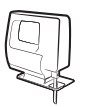
Install CooktopSTEP 1: Place cooktop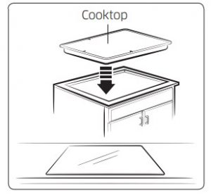
Insert the cooktop centered into the cutout opening. Make sure the cooktop is parallel to the front edge of the countertop. Make final check that all required clearances are met.
Installation Instructions
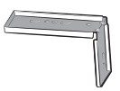
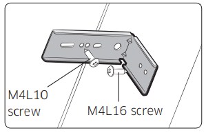
STEP 2-1Installing the bracket guide The bracket Guide can be installed after cooktop is placed into the cutout.
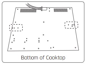
- On the bottom of the cooktop, find the holes where the bracket guide attaches. (Refer to the figure.)
- Place the bracket guide onto the hole, and then move it towards the sidewall of the cabinet until it touches the sidewall.
- Use the screws to fasten the bracket guide to the cooktop and the sidewall.
![]() NOTE
NOTE
- Make sure you attach the bracket guides on the left and right side.
- Make sure that the front edge of the cooktop is parallel to the front edge of the countertop. If repositioning is needed, lift entire cooktop up from cutout to avoid scratching the countertop.
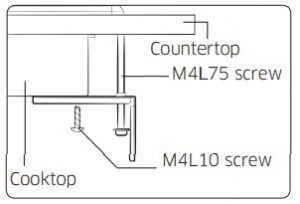
STEP 2-2 Alternative Bracket Guide Installing
- Attach bracket guide to bottom and select bracket location.
- Tighten screw bracket guide to base of cooktop.
- Install M4L75 screw until bracket touches the bottom of the countertop.
Make Electrical ConnectionThis cooktop is manufactured with ground wire (bare or green) connected to the cooktop frame. Connect the cooktop cable to the junction box through the UL listed or CSA approved conduit connector.
Electrical Connection Options
|
If your home has: |
And you will be connecting to |
Go to section: |
| 4-wire direct |
A fused disconnect or circuit breaker box | 4-Wire Cable from Power supply to 3-Wire Cable from Cooktop |
| 3-wire direct |
A fused disconnect or circuit breaker box | 3-Wire Cable from Power supply to 3-Wire Cable from Cooktop |
4-Wire Cable from Power Supply to 3-Wire Cable from CooktopIMPORTANT: Use the 4-wire cable from power supply where local codes do not permit connecting the frame-ground conductor to the Neutral (N) junction box wire.
- Disconnect power.
- Remove Junction box cover if present.
- Connect the flexible cable conduit from the cooktop to the junction box using a UL listed or CSA approved conduit connector.
- Tighten screws on conduit connector, if present.
- Connect the two L2 wires together using.
- Connect the two L1 wires together using the UL listed wire connectors.
- Connect the Ground (G) or bare ground wire from the cooktop cable to the Ground (G) or bare ground wire (in the junction box) using a UL listed wire connectors.
- Put a UL listed wire connector on the end of the Neutral wire.
- Install junction box cover.
- Reconnect power.
- A. 4-wire cable from power supply
- B. L1 wires
- C. Ground (G) or bare ground wire (from cooktop)
- D. 3-wire cable from cooktop
- E. Junction box
- F. Neutral wire (from power supply)
- G. UL listed wire connector
- H. L2 wires
- I. UL listed or CSA approved conduit connector.
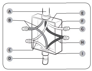
![]() NOTE
NOTE
- Usually L1 is Black, L2 is Red, Ground (G) is Green or bare wire and Neutral (N) is White wire.
- Do not connect the bare ground wire to the Neutral (N) wire in the junction box.
3-Wire Cable from Power Supply to 3-Wire Cable from Cooktop
IMPORTANT: Where local codes permit, 3-wire cable can be use to supply power. In those cases connect connect cooktop ground wire to the neutral wire from the junction box.
- Disconnect power.
- Remove Junction box cover, if present.
- Connect the flexible cable conduit from the cooktop to the junction box using a UL listed or CSA approved conduit connector.
- Tighten screws on conduit connector, if present.
- Connect the two L2 wires together using
- Connect the two L1 wires together using the UL listed wire connectors.
- Connect the Ground (G) or bare ground wire from the cooktop cable to the Ground (G) or bare ground wire (in the junction box) using a UL listed wire connectors.
- Install junction box cover.
- Reconnect power.
- A. 3-wire cable from power supply B. L1 wires
- C. Ground (G) or bare ground wire (from cooktop)
- D. 3-wire cable from cooktop
- E. Junction box
- F. Neutral wire (from power supply)
- G. UL listed wire connector
- H. L2 wires
- I. UL listed or CSA approved conduit connector.
Installation Instructions
Complete Installation
- Check that all parts are now installed. If there are any extra parts go back through the steps to see if any steps were skipped..
- Check that you have all of your tools.
- Dispose of/recycle all packaging materials.
- Use a mild solution or liquid household cleaner and warm water to clean cooktop before use. Dry thoroughly with a soft cloth. For more information, see the User’s Manual.
- Reconnect power.
If You Need Assistance or Service:Please reference the “User Manual” or contact the dealer from whom cooktop was purchased.

Scan the QR code* or visit www.samsung.com/spsn to view our helpful. How-to Videos and Live Shows*Requires reader to be installed on your smartphone
Questions or Comments
|
COUNTRY |
CALL |
OR VISIT US ONLINE AT |
| U.S.A
Consumer Electronics |
1-800-SAMSUNG (726-7864) | www.samsung.com/us/support |
| CANADA | 1-800-SAMSUNG (726-7864) | www.samsung.com/ca/support |
References
[xyz-ips snippet=”download-snippet”]