![]()
Instruction manualLuik LED Bulkhead & Gear Tray61646, 6164/7, 61648, 61649, 61650, 61651, 69231, 69232, 69233
Thank you for purchasing this light fitting. Please read the instructions carefully before use to ensure safe and satisfactory operation of this product. Please retain these instructions for future reference.
Warning
Please read these instructions carefully before commencing any work. This unit must be fitted by a competent and qualified electrician. Install in accordance with the IEE Wiring regulations and current Building Regulations. Check the pack and make sure you have all the parts listed.To prevent electrocution switch off at the mains supply before installing or maintaining this fitting. Ensure other persons cannot restore the electrical supply without your knowledge. This light fitting should be connected to a circuit with a 30mA RCD fitted. If replacing an existing fitting, make a careful note of the connections. The mains supply cable must have a minimum cross-section area of 1.0mm2. The products can be wall or ceiling mounted. If wall mounting ensure that the power supply is at the bottom. Please note that the entire unit gets hot whilst on for a period of time.
Technical data
Supply Voltage: 940 V~50 HzBulb Type: LED (18W) 4200K
The light source of this luminaire is not replaceable; when the light source reaches its end of life the whole luminaire or the gear tray shall be replaced
| Conformity wilt all relevant EC Directive requirements. | |
| Class I product, must be connected to earth | |
| Waste electrical products should not be disposed of with household waste. Please recycle where facilities exist. Check with your Local Authority or local store for recycling advice. | |
| This product is rated at IP65. |
Emergency
| Duration: 3 hours (180 Minutes)Operating Temperature: 0 °C-50°CMaximum Operating Humdity: 90% | Change over time: Approximately 1sBattery Specification: LiFePO4 3.2V 1500mAhBattery Charge Time: 24 HoursBattery warranty: 2 years |
Available combinations
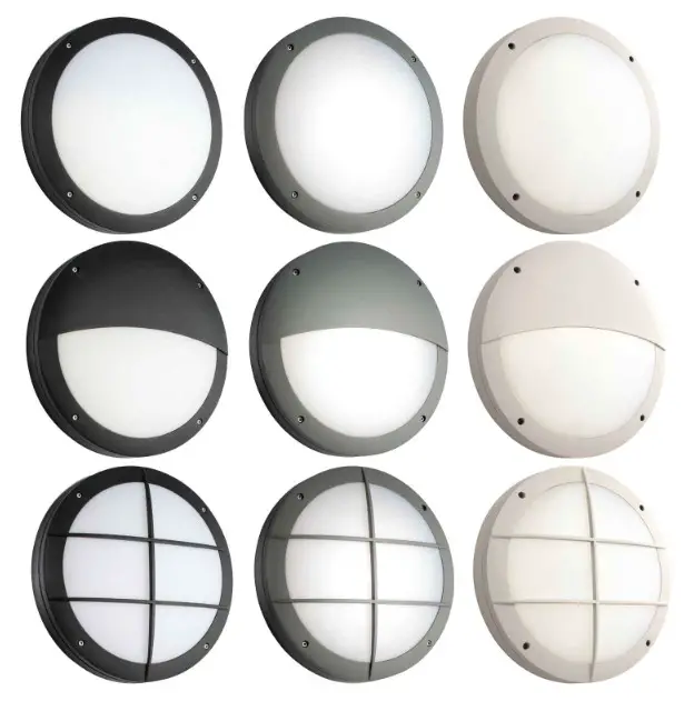
Casing:
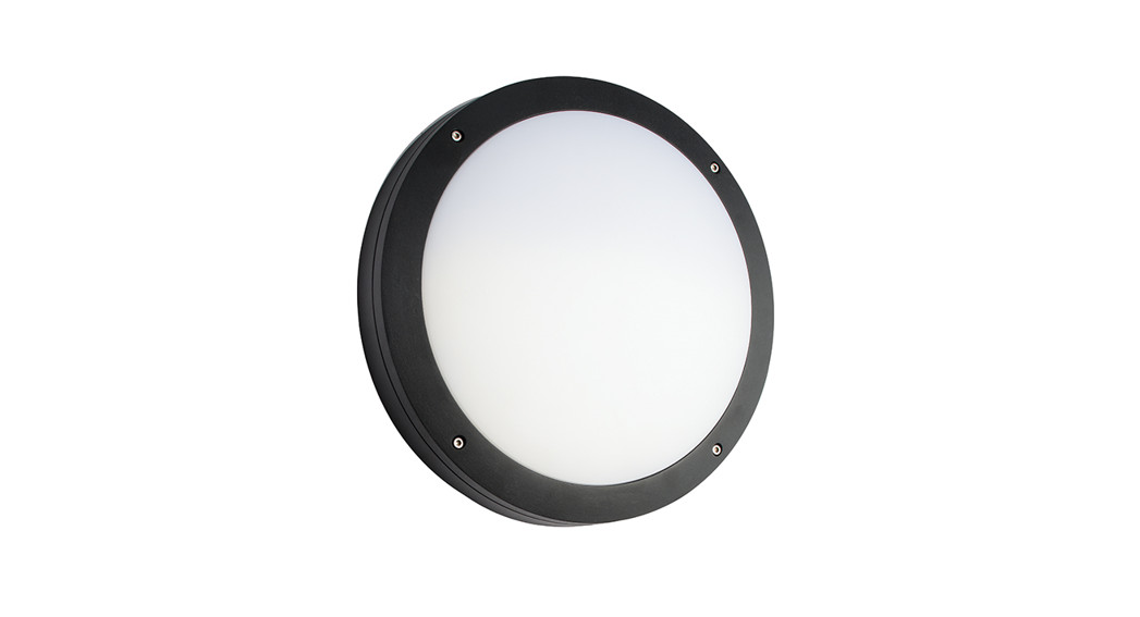
| 61646 : Black plain61648 : Black eyelid61650 : Black grill | 69231 : White plain69232 : White Eyelid69233 : White Grill | 61647 : Grey plain61649 : Grey eyelid61651 : Grey grill |
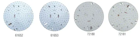
Gear tray:
| 61652: standard (non-dimmable)72180: Microwave | 61653: Emergency72181: Emergency + Microwave |
Installation
Exising fitting must be completely removed before installation of a new product. Before removing the existing fitting, carefully note the position of each set of wires.
- Note that the switch is closed before installation.
- The surface must be flat and smooth to ensure a good fit.
- Ensure the wall is capable of holding the weight of the product, or if fitting to a ceiling, ensure there is a joist at the point of fixing to support the weight of the product. take care to avoid damaging any concealed wiring and pipes. The correct fixings should be used for brick, cavity walls or plasterboard.
- The help of an assistant is recommended when installing this fitting.
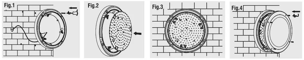
- Remove the shade from the fitting by loosening the screws with the supplied hex key.
- Using the casing as a template, mark the position of the fixing holes. The casing has 4 “knock outs” for cable or conduit entry. It is necessary to knock out the appropriate panel to allow the supply cable to enter the casing. If using conduit, a hole will also need to be drilled through the outer rim to fit the conduit. The knock out must be fitted with a rubber grommet to protect the cable.
- Fix the wall back in place using the supplied screws and wall plugs (Fig. 1).
- Locate the gear tray onto the retaining clips (Fig. 2).
- Rotate the clips to secure the tray into the casing (Fig. 3).
- Refit the polycarbonate diffuser and outer bezel (Fig. 4).
- Connect the wiring. Your light is now ready for use.

Emergency Operation
- This unit works in maintained mode. The fitting can be switched separately on or off. The unit will charge automatically (LED is green). Several LEDs will remain on when the supply is interrupted.
- Locate the flying lead on the inverter and plug into the connector.
- Replace fuse or circuit breaker and switch on. Ensure that the source is mains (240V ~ 50Hz).
- Verify that the Green LED is illuminated; this confirms that the batteries are charging.
- Charge the battery for at least 24 hours before first use.
- If the LED is not illuminated then there may be no a.c. supply, the battery has not been connected properly or the internal circuit may have failed.
- The battery should be re-charged and checked every three months.
- The battery should be discharged and the duration of the lamp in emergency mode checked every six months.
Battery Replacement
- After routine operation check, the lamp does not remain lit for the Set period, a new battery may be required.
- Switch off the electricity at the mains, allow batteries to fully discharge then reconnect to supply and allow to charge for 24 hours.
- Test again for two hours, if light does not remain lit change the inverter/battery unit as follows:
- Obtain a replacement battery/inverter unit. make a note of the wiring, and remove from plate and refit the new one. Undo the screws under the battery. to release it from the gear tray and unplug it from the driver. Plug the new battery into the driver and refit the screws to secure the new battery to the gear tray.
- Perform full operation check and update test record.
- Refit the shade. Ensure that the seal is correctly located. Restore power and allow to charge for 24 hours.
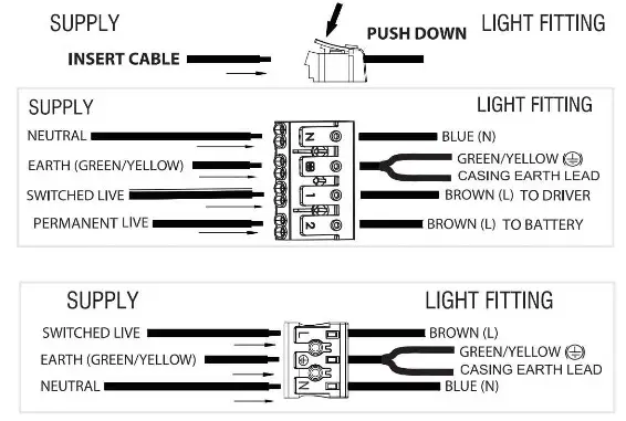
Wiring (For 61653 and 72181 gear tray)
NOTE: The Earth cable connected to the casing must be connected to the output side of the terminal block. This product can be configured in the following formats:
- Non-maintained- connect a Permanent live feed to terminal marked °2”
- Maintained- connect a Live feed to terminal marked “1” add a jumper between terminals “1” and “2”
- Switch maintained- connect a switched live feed to terminal marked “1” and permanent live feed to Terminal marked “2”
Wiring (For 61652 and 72180 gear tray)
Having correctly identified the supply wiring, connect to the connection block mounted to the rear of the gear tray as shown below.NOTE: The Earth cable connected to the casing must be connected to the output side of the terminal block.
Check that…
- You have to correctly identified the wires.
- The connections are tight.
- No loose strands have been left out of the connection block.
Microwave Movement Sensor
- This product is fitted with a microwave movement sensor. Please see below detailed operating instructions.
Technical Specifications:
| Operating voltage | 220 ~ 240 VAC 50/60Hz |
| Rated load | 400W (Capacitive load) 800W (Resistive load) |
| Stand-by power | <0.5W |
| Sensitivity | 10% / 50% / 75% / 100% |
| Hold-time | 5s / 90s / 5min / 15min |
| Daylight sensor | 2lux / 101ux / 501ux, disable |
| Microwave frequency | 5.8 GHz +/- 75MHz |
| Transmitting power | <0.2mW |
| Detection range | maximum (diameter x height): 10m x 6m |
| Detection angle | 30° ~150° |
| Working temperature | -20°C ~ 60°C |
 report this ad
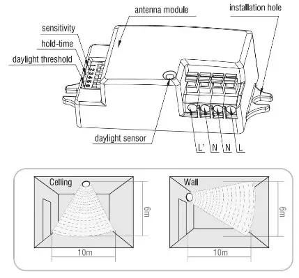
Settings:
1. SensitivitySensitivity can be adjusted by selectingthe combination on the DIP switches fordifferent applications.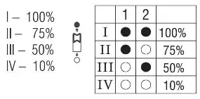 |
2. Hold-timeHold-time refers to the time period thatthe light remains 100% on if no moremovement is detected.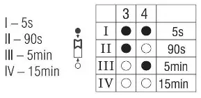 |
3. Daylight sensorDifferent daylight threshold can be preset onDIP switches. Light will always turn on uponmovement if daylight sensor is disabled.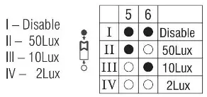 |
Trouble shooting:
| Malfunction Cause Remedy | Cause | Remedy |
| The light will not come on | Incorrect light-control setting selected | Adjust daylight threshold setting |
| Faulty lamp | Replace lamp | |
| No power supply | Check power to sensor | |
| The lamp is always on | Continuous movement in the detection zone | Check detection area setting |
| The lamp is on without any identifiable movement | The sensor is not mounted for reliably detecting movement | Securely mount enclosure |
| Movement occurred, but not identified by the sensor (Movement behind wall, movement of small object in immediate lamp vicinity etc.) | 1. Reduce sensitivity.2. Check the movement behind walls to avoid facilities such as water pipe, fan, which may mis-trigger the sensor. | |
| The lamp will not work despite movement | Rapid movements are being suppressed to minimize malfunctioning or the detection radius is too small. | Check detection area setting |
Care and Safety
- We recommend cleaning with a soft dry cloth. Do not use solvents or abrasive cleaners as these could damage the finish.
- For your safety, always switch off the power supply before cleaning.
V4 17/02/2020Saxby Lighting. BH17 7BY![]() www.saxbylighting.com
www.saxbylighting.com
[xyz-ips snippet=”download-snippet”]