

Installation InstructionsBE367/BE367F
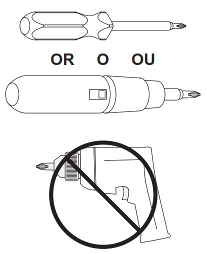
Tools
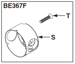
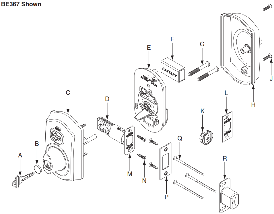
A. KeyB. Cylinder CapC. iButton AssemblyD. DeadboltE. Mounting PlateF. 9v BatteryG. Mounting Screws (2)H. Thumbturn AssemblyJ. Screws (2)K. Drive-in FaceplateL. Square-corner FaceplateM. Rounded-corner FaceplateN. Deadbolt/Strike Screws (4)P. StrikeQ. Reinforcement Screws (3)R. Dust BoxS. UL Cup (BE367F ONLY)T. UL Screw (BE367F ONLY)
Install Lock
1 Template Is Included In Box
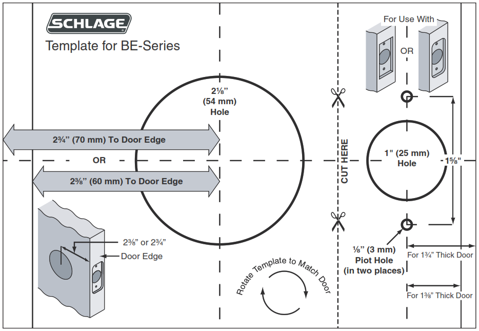
IMPORTANT: Template shown is not full size
2 Check Door Holes
Note: If holes do not match template, purchase a GuideRight® jig or visit www.schlage.com for door drilling instructions.

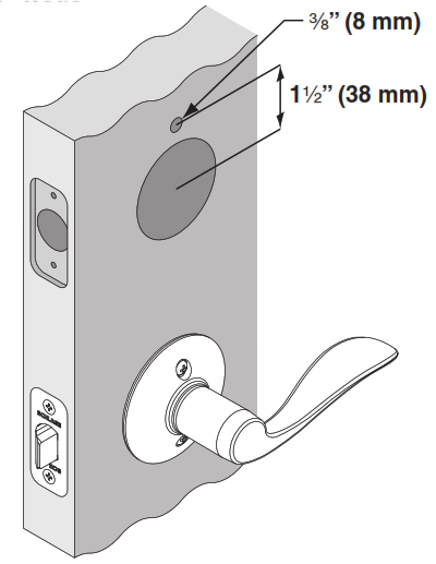
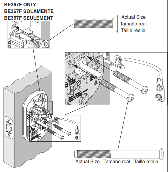
3 FOR BE367F ONLY: Measure and Drill Hole
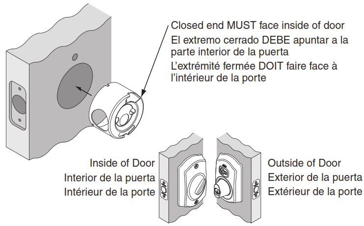
4 FOR BE367F ONLY: Install UL Cup
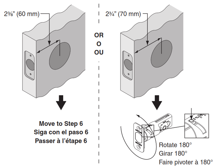
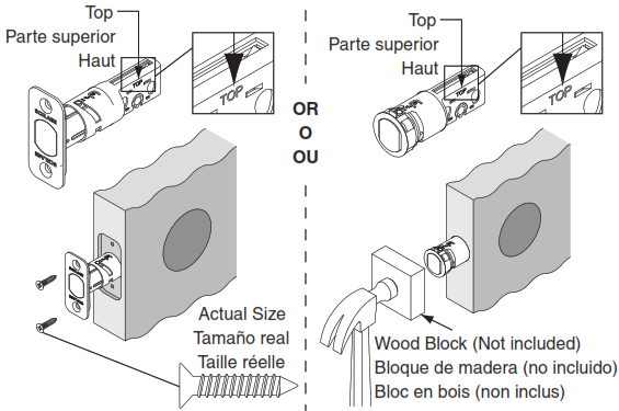
5 If Needed, Adjust Deadbolt
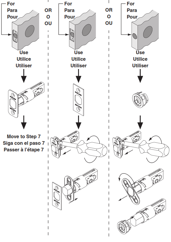
6 Choose Deadbolt Faceplate
Match faceplate to your door.
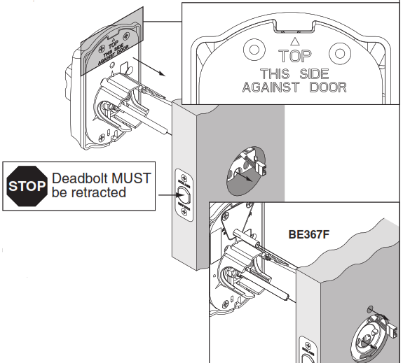
7 Install Deadbolt
8 Install Keypad Assembly
IMPORTANT: Cable passes over top of deadbolt.
9 Install Inside Mounting Plate
IMPORTANT: Pull excess wire through mounting plate.
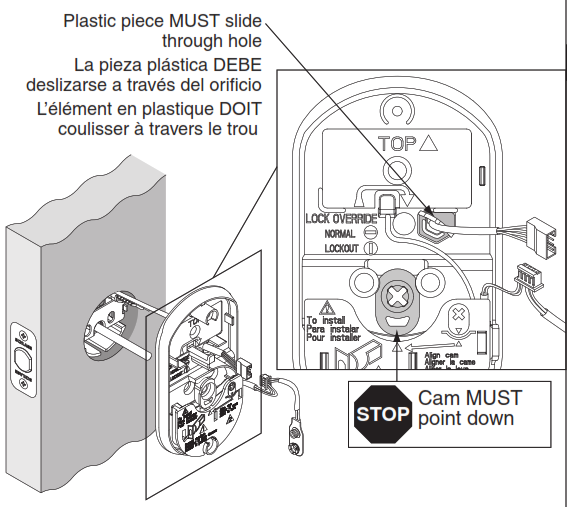
10 Check Cam and Install Screws
NOTE: Ensure lock is straight before tightening.
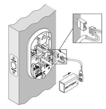
11 Install Battery and Connect Cables
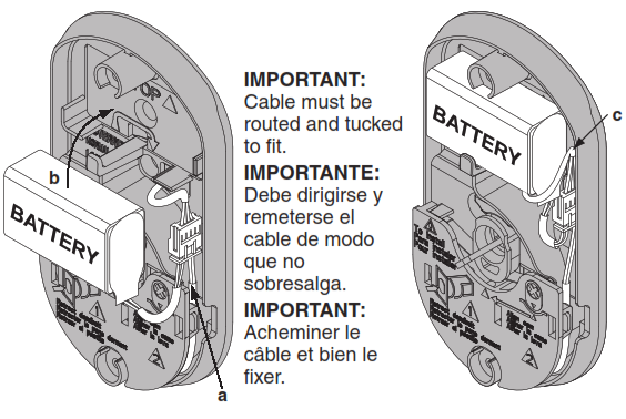
12 Route and Tuck Cables
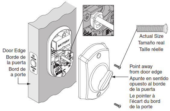
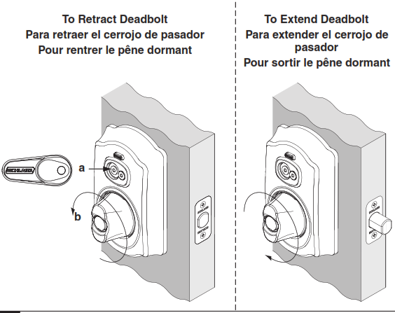
13 Install Thumbturn
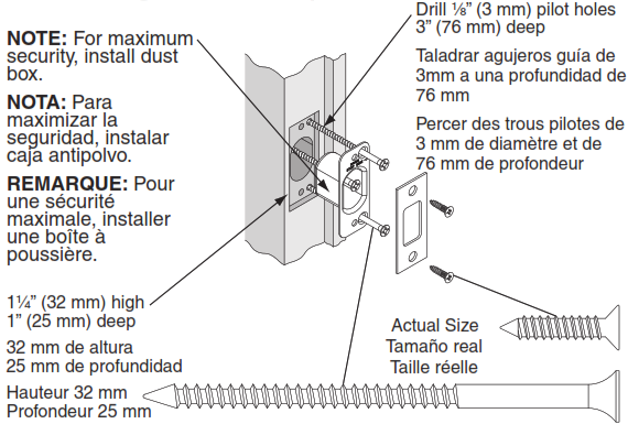
14 Install Strike and Dust Box
Check Operation
A If you have a yellow construction iButton Credential, then test lock operation
IMPORTANT: If the BE367 is unprogrammed, then all yellow construction iButtons will operate lock. Yellow Construction iButtons are disabled automatically when the BE367 is programmed.
B For Programming, See the SMS/SMS Express Site Set-Up Guide
Questions? (888) 805-9837
![]()
© Allegion 2014Printed in U.S.A.P515-488 Rev. 11/14-online
Schlage BE367/BE367F Camelot Programmable keyless Deadbolt Installation Manual – Schlage BE367/BE367F Camelot Programmable keyless Deadbolt Installation Manual –
[xyz-ips snippet=”download-snippet”]